1
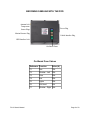
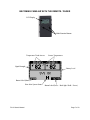
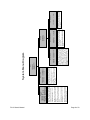
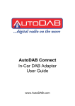
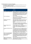
Gen
2
USER’S MANUAL
System Serial No.___________________
TABLE OF CONTENTS
SECTION
PAGE
Feature Descriptions....................................................................................3
Becoming Familiar with the HUD..................................................................5
Becoming Familiar with the POD..................................................................6
Becoming Familiar with the Remote/Pager..................................................7
Starting Your System....................................................................................8
Accessing the System Menu........................................................................8
System Menu Diagram.................................................................................9
Heat Alert System Status Details...............................................................10
Remote/Pager Status Details.....................................................................10
Product Care & Service..............................................................................11
Troubleshooting..........................................................................................11
Warranty.....................................................................................................12
Disclaimer...................................................................................................13
F2-G2 User's Manual
Page 2 of 13
FEATURE DESCRIPTIONS
1
2
3
4
Heads Up Display
The Heads Up Display (HUD) is the primary user interface used to monitor real-time
temperature measurements and system status, manually control the kennel's fan, and
adjust system settings. The HUD is equipped with an adjustable back-light for low-light
conditions. When an alert condition exists, the HUD will display the alert message and
can be used to reset the alert.
1.1 HUD Back-light
The HUD is equipped with a back-light for the display. It is controlled by the left
button and can be set to one of three brightness levels or turned off. When the
system is powered up, the back-light will return to the brightness level it was set at
when it was last turned off.
Remote/Pager
The Remote/Pager (RP) is the portable interface to the system. It displays almost exactly
the same information as the HUD. The RP will notify of an alert condition by vibrating and
beeping (unless muted in which case it will only vibrate) and can be used to reset the alert.
After approximately one minute of no buttons being pressed, the display will turn off to
conserve battery power, but the RP will continue to receive updates.
2.1 Remote/Pager Back-light
The RP is equipped with a back-light for the display. It can be turned on by pressing
the right button
2.2 Remote/Pager Rechargeable Battery
The RP is powered by a lithium-polymer rechargeable battery that will give 80 to 100
hours of operation on a full charge. It can be recharged using either the included
120V wall charger or the included charging pigtail which allows the RP to be
recharged from the HUD. It could take more than an hour to fully recharge the
battery. The RP employs smart charging techniques to protect the battery from
being over-charged allowing the RP to be plugged into the charger for long periods
of time without causing damage. This type of battery also does not have a “memory”
effect and so there is no need to fully discharge the battery before recharging.
Non-Volatile Memory
The system settings are saved in non-volatile memory on the POD. This means that even
if power is disconnected from the system, the settings are saved and don't need to be
reset.
Heat Alert
The heat alert system monitors temperature, vehicle power, and motion inside the kennel
(optional) to determine if the K9 is in danger of overheating.
4.1 Alert Delay
The alert delay postpones the heat alert function after system start-up or an alert
reset. The duration of the delay is adjustable in the Heat Alert menu.
4.2 Vehicle Power Monitor
The voltage that is fed to the system is monitored for low voltage conditions. If the
voltage drops below a specific level, a Vehicle Power Alert will be triggered.
4.3 Auxiliary Alert
The system is equipped with an auxiliary input. An Aux Input Alert is triggered when
this input is activated.
F2-G2 User's Manual
Page 3 of 13
4.4 Temp Sensors
The system utilizes two digital temperature sensors for high accuracy as well as
decreased false alarms. Both the of temp sensors must be at or over the Alert
Temp set in the Heat Alert menu to trigger an alert.
4.5 Window Drop
The windows that are selected in the Heat Alert menu will roll down one at a time
when a heat alert is triggered. The menu option can be set to roll down just the left,
just the right, or both windows.
4.6 Fan Control
The optional fan is controlled both manually and automatically. The manual fan
control is through the right button of the HUD and can be set to three different
speeds or turned off. When a heat alert is triggered and after the selected windows
have rolled down, the system will automatically turn the fan on at full speed to aid in
cooling down the kennel.
4.7 Motion Sensing
The motion sensor is an optional feature that will detect motion inside the kennel for
a specified amount of time after the system has been turned off. There are multiple
adjustments that can be made to the timing of this feature. First, the Detect Delay is
the number of minutes after the system is turned off before the system begins
watching for motion. Next, the Detect Duration is the number of minutes the system
watches for motion. Finally, the Alert Delay is the number of minutes the system will
wait after motion has been detected before the actual alert is triggered.
F2-G2 User's Manual
Page 4 of 13
BECOMING FAMILIAR WITH THE HUD
LCD Display
Multi-Function Buttons
Remote/Pager Charging Port
Temperature Trend Arrows
POD Interface Jack
Sensor Temperatures
Heat Alert
System Status
Back-light Level
Fan Speed
Button Label (Back-light)
Button Label (Fan)
Button Label (Press – Menus / Hold - Power)
F2-G2 User's Manual
Page 5 of 13
BECOMING FAMILIAR WITH THE POD
Antenna Jack
Temperature
Sensor Plugs
Power Plug
Motion Detector Plug
Vehicle Interface Plug
HUD Interface Jack
On-Board Fuses
On-Board Fuse Values
F2-G2 User's Manual
Reference Function
Value (A)
F1
Fan
15A
F2
Window - Left
30A
F3
Horn
25A
F4
Aux
25A
F5
Lights
25A
F6
Not Used
N/A
F7
Window - Right 30A
Page 6 of 13
BECOMING FAMILIAR WITH THE REMOTE / PAGER
LCD Display
Multi-Function Buttons
Temperature Trend Arrows
Sensor Temperatures
Signal Strength
Battery Level
Button Label (Mute)
Heat Alert System Status
F2-G2 User's Manual
Button Label (Press – Back-light / Hold - Power)
Page 7 of 13
STARTING YOUR SYSTEM
To power-up the system, hold down the center button located on the Heads Up Display
(HUD). Release the button when the LCD changes. The system will perform a complete
self diagnostic. The display will show two independent temperature readings, and
system status indicators. Along the bottom are controls for the back-light, fan (left and
right button respectively), and menu access / power button.
Note: Your system is powered by direct connection to the vehicle battery and will
remain on and functioning even when the vehicle is turned off. Therefore when your
vehicle is not in service and/or you no longer require this system to function, you must
manually turn the system OFF (press and hold the center button of the HUD).
ACCESSING THE SYSTEM MENU
Access the particular system you wish to program by first pressing the center button on
the HUD once. This brings you to the first level of your Setup menu.
To access the feature sub-menus, select the desired feature with the left and right
buttons and then press the center button to enter that sub-menu.
To change a feature option, select the desired option with the left and right buttons and
then press the center button to edit that option. The left and right buttons can then be
used to change the option value. Once the option has been set to the desired value,
pressing the center button will allow another option to be selected for editing.
Holding the center button will exit out of the current sub-menu or menu.
F2-G2 User's Manual
Page 8 of 13
F2-G2 User's Manual
Page 9 of 13
Alarm Mode: Sets which audible/visual alarms
should be activated when the alarm delay has
expired after an alert is triggered.
Window Drop: Sets which window(s) will drop
when a heat, vehicle power, auxilliary, or motion
alert is triggered.
Alert Delay: Sets the initial delay after system
startup or a reset alert before heat alert system
is active.
Alert Temp: Sets the temperature that both
temperature sensors must reach to trigger a
heat alert.
Temp Units: Sets temperature measurement
units to fahrenheit or celcius.
Heat Alert: Enables or disables heat alert
system. Vehicle power alert and motion alert (if
installed) are also affected by this setting.
HEAT ALERT
HEAT ALERT: OFF/ON
TEMP UNITS: F/C
ALERT TEMP: 70F – 99F (85)
ALERT DELAY: 0m – 10m (2)
WINDOW DROP: OFF/LEFT/RIGHT/BOTH
ALARM MODE: OFF/LIGHTS/HORN/BOTH
Alert Delay: Sets the number of minutes
between motion being detected and an alert
being triggered.
Detect Duration: Sets the number of minutes
the system will watch for motion.
Detect Delay: Sets the number of minutes the
system will wait before watching for motion.
1m – 10m (5)
5/10/15/20/25/30/CONT
1m – 3m (2)
MOTION TIMERS
DETECT DELAY:
DETECT DUR:
ALERT DELAY:
Aux Time: If AuxMode is set to a single pulse,
this sets the duration of the pulse. If Aux Mode
is set to continuous pulsing, this sets the
duration of each pulse (and duration of each
break between pulses) or half the period. If Aux
Mode is set to continuous output, this setting
has no effect.
Aux Mode: Sets the type of auxilliary output
when an alert is triggered (either none, a single
pulse, continuous pulsing until the alert reset, or
a continuous high output until the alert is reset).
OFF/SNGL/PLS/CONT
1s – 20s (1)
ADV - AUX OUTPUT
AUX MODE:
AUX TIME:
DEPLOYMENT
HEAT ALERT
MOTION TIMERS
ADVANCED
SETUP
System Menu Diagram
ADVANCED
0s – 99s (30)
1s – 15s (5)
Window Time: Sets the number of seconds
the window outputs will activate when dropping
windows.
Alarm Delay: Sets the number of seconds after
an alert is triggered before the audible/visible
alarm is activated.
ALARM DELAY:
WINDOW TIME:
ADV – OUTPUT TIMING
AUX OUTPUT
OUTPUT TIMING
RF PARAMS
11 – 25 (14)
RF Channel: Sets the radio frequency channel
to be used for wireless communications with the
Remote/Pager.
RF CHANNEL:
ADV – RF PARAMS
Heat Alert System Status Details
Displayed Message
ALERT!
HIGH TEMP ALERT
ALERT!
VEHICLE POWER
ALERT!
MOTION
ALERT!
Event Description
Remote/Pager Behavior
The in-vehicle temperature Continuous,
alternating
is at or above the Alert vibrator and beeper (No
Temp at both sensors.
beeper if ‘MUTE’ is enabled).
The vehicle battery voltage Continuous,
alternating
has
dropped
below vibrator and beeper (No
approximately 8 volts.
beeper if ‘MUTE’ is enabled).
The
motion
detector Continuous,
alternating
(optional)
has detected vibrator and beeper (No
motion inside the vehicle beeper if ‘MUTE’ is enabled).
while the system is powered
down
The auxiliary input
received a pulse.
AUX INPUT
has Continuous,
alternating
vibrator and beeper (No
beeper if ‘MUTE’ is enabled).
Remote/Pager Status Details
Displayed Message
LOW BATTERY
NO SIGNAL XX:XX
F2-G2 User's Manual
Event Description
Remote/Pager Behavior
The Remote/Pager battery Periodic vibration and beep
needs to be recharged to (No beeper if ‘MUTE’ is
ensure continued operation. enabled)
The Remote/Pager has not
received a signal from the
POD for the time specified
(approximate)
Vibration and beep after 2
minutes and every 10 minutes
after signal is lost (No beeper
if ‘MUTE’ is enabled)
Page 10 of 13
PRODUCT CARE AND SERVICE
Your system has been designed to give years of trouble free use. Great effort was given
to the selection of the highest quality components and fixtures. Following are tips and
suggestions that will help keep your system fully functional.
Heads Up Display
The Heads Up Display (HUD) can be cleaned with a soft, damp cloth. Do not use
abrasive cleansers as they can damage the LCD panel and the housing. Your HUD
requires no additional user maintenance.
Remote / Pager
Your Remote/Pager (RP) is designed to be carried on a law enforcement duty belt.
Included with your system is a custom belt holster that is engineered to offer durability,
ease of use, and comfort when carrying the RP.
Your RP can be cleaned with a soft, damp cloth. Do not use abrasive cleaners as they
can damage the LCD panel and the case. Do not submerge the RP in water. However, if
the RP does become immersed in water, turn it off immediately. Allow the RP to
completely dry before attempting to turn it on again.
TROUBLESHOOTING
•
•
•
The Remote/Pager is frozen and won't turn ON/OFF.
◦ The RP can be reset by momentarily holding down both of the front buttons at
the same time.
The range of the Remote/Pager is not very good.
◦ The wireless connection between the RP and the POD can be changed to a
different channel if there are issues with interference. The channel can be
changed on the POD by accessing the appropriate menu through the HUD. To
change the channel on the RP, hold down the left, front button while the RP is
powered down. Skip through the first screen which is used to set the serial
number of the POD that the RP is to connect to. The next screen allows you
to change the channel number.
The system turns off when the RP is plugged into the HUD charging cord.
◦ When the RP battery is very low, sometimes the initial power demand causes
the system to shut down. The system can be powered back up immediately
and system operation should continue normally.
F2-G2 User's Manual
Page 11 of 13
WARRANTY
Two Year Warranty
Ray Allen Manufacturing, LLC guarantees the purchaser that this F Series System will
perform without defect in materials and workmanship for a period of two years from date
of purchase. Ray Allen Mfg. will replace or repair defective materials at its discretion.
Exclusions to this warranty include, but are not limited to, acts of God or nature, vehicle
accidents, product misuse or alteration (without the explicit direction of Ray Allen) or
improper installation. Warranty does not include cost of removal, installation, labor, or
any other cost incurred by purchaser. Ray Allen Manufacturing, LLC assumes no
responsibility or liability for installation, use or misuse of the F Series System.
This warranty is valid for the original installation of this unit and is voided if the F Series
System is removed from the originally installed vehicle and installed into another vehicle.
Warranty service requests are to be reported by phone to Ray Allen at (800) 444-0404
or sent in writing via e-mail to [email protected]. Requests require the serial # of
the System and original sales order number to be processed.
To activate your warranty, register your product on the Ray Allen website. Go to the
following link to process your registration:
www.rayallen.com/fseries/register
F2-G2 User's Manual
Page 12 of 13
Disclaimer
Ray Allen Manufacturing, LLC can, at its discretion and without prejudice, make
improvements to these products at any time. These improvements may or may not be
made available to previously purchased products.
This product is designed for sale and use within the United States of America and its
territories. Ray Allen Manufacturing, LLC will assume no liability or responsibility for any
use or installation of this system outside of the USA. Such use is the sole responsibility
of the purchaser.
This equipment has been tested and found to comply with the limits for a Class B digital
device, pursuant to part 15 of the FCC Rules. These limits are designed to provide
reasonable protection against harmful interference in a residential installation. This
equipment generates, uses and can radiate radio frequency energy and, if not installed
and used in accordance with the instructions, may cause harmful interference to radio
communications. However, there is no guarantee that Interference will not occur in a
particular installation, If this equipment does cause harmful Interference to radio or
television reception, which can he determined by turning the equipment off and on, the
user is encouraged to try to correct the interference by one or more of the following
measures:
—Reorient or relocate the receiving antenna
—Increase the separation between the equipment and receiver
—Connect the equipment into an outlet on a circuit different from that to which the
receiver is connected
—Consult an experienced technician for help
This device complies with part 15 of the FCC Rules. Operation is subject to the
following two conditions: (1) This device may not cause harmful interference, and (2) this
device must accept any interference received including interference that may cause
undesired operation.
Caution: changes or modifications not expressly approved by Ray Allen Manufacturing,
LLC could void the user’s authority to operate the equipment.
F2-G2 User's Manual
Page 13 of 13