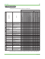
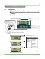
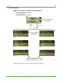
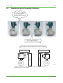
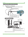
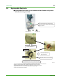
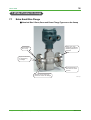
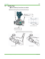
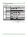
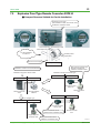
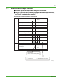
1
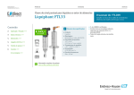
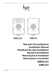
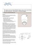
Technical
Information
Magnetic Flowmeter
ADMAG AXF
TI 01E20A01-20E
F000000.eps
Contents
1.
Introduction ..................................................................................................... 3
2.
Application ....................................................................................................... 4
3.
ADMAG AXF Series Lineup ............................................................................ 5
4.
Product Concept ............................................................................................. 6
5.
User-oriented Functionality ............................................................................. 7
5.1
5.2
5.3
6.
High Quality/High Performance ..................................................................... 12
6.1
6.2
6.3
7.
LCD Indicator .................................................................................................... 7
Compact and Light-weight Design .................................................................. 10
Flexible Electrical Connection Direction .......................................................... 11
Fluid Adhesion Level Diagnosis ...................................................................... 12
Replaceable Electrode .................................................................................... 13
Enhanced Dual Frequency Excitation ............................................................. 14
Wide Product Lineup ..................................................................................... 16
7.1
7.2
7.3
7.4
7.5
7.6
Extra Small Size Flange .................................................................................. 16
Sanitary type ................................................................................................... 17
Size, Lining and Materials ............................................................................... 18
Face-to-face Length ........................................................................................ 20
Explosion Proof Type Remote Converter AXFA14 .......................................... 21
Versatile Input/Output Function ....................................................................... 22
Yokogawa Electric Corporation
2-9-32 Nakacho, Musashino-shi, Tokyo 180, Japan
Tel.: 81-422-52-4443 Fax.: 81-422-52-2018
TI 01E20A01-20E
©Copyright July. 2006
1st Edition July. 2006
3
<Toc> <Ind>
1. Introduction
Yokogawa developed the first industrial magnetic flowmeter in Japan in 1955, and in 1988, the
world’s first dual frequency excitation method: ADMAG series was released. Afterwards, we have
developed ADMAG AE which has the lineup of the flameproof construction of the integral type,
and ADMAG CA of capacitance type which has no wetted electrode. Thus we have been leading
the technology of this field and sold 350,000 or more units.
And now, true user-oriented functionality was achieved succeeding to high performance and the
high quality as a successor of these series, the function was developed more greatly, and enhancing
was developed.
ADMAG AXF series is a product that has the best ability in the world to enhance the function of
the conventional model. When developing, we heard the demand from the various customers, and
most of the demands were achieved.
Pulp & Paper
Food & Beverage
Dressing
More Enhanced
Applications
for ADMAG AXF
Sauce
Blow Line
DIP
Pulp
Dye
Starch
Beer
Beverage
White Liquor
Black Liquor
Gelatin
Retort Food
Dessert including Fruit
Flesh
Utility
Latex
Blast Furnace Tuyere
Cooling Water
Hydrochloric acid
Sulfuric acid
Sodium hydroxide
Various type of Resin
Continuous Cast
Cooling Water
Chemical
Iron & Steel
Application for the
general magnetic flowmeter
F010001.eps
This figure is an application chart of each industry. Using ADMAG AXF series provides the
customer the flow measurement of wider application.
In this TI (Technical Information), we introduce the example of the application and the functionality
of ADMAG AXF series etc. Please read through this TI and select the ADMAG AXF series for your
flow measurement.
Please confirm details of the specification with General Specification sheet. It can be found in the
following URL.
http://www.yokogawa.com/fld/FLOW/AXF/index.htm
All Rights Reserved. Copyright © 2006, Yokogawa Electric Corporation
TI 01E20A01-20E
2006.07.21-00
4
<Toc> <Ind>
2. Applications
Following table shows the example of application for ADMAG AXF.
Feature of AXF
Environment Construction
Pulp & Paper
Chemical
Low Conductivity Fluid
Oily Adhesive Fluid
Solid included Liquid
Blast Furnace Tuyere
Baste
Cooling Water
Adhesive Fluid
Electrolysis Plant
Low Conductivity Fluid
√
√
√
Latex, Various types of Resin,
√
√
√
√
√
Electrolysis Solution
Pure Water, Alcohol, Acetic Acid,
√
√
√
√
√
√
√
PVC Piping
Organic Solvent
Strong Acid, Strong Alkali
Digester
Black Liquor
DIP
Pulp
√
√
√
√
Adhesive Liquid such as Chlorine,
√
√
√
√
Size agent, Aluminum Sulfate
√
√
√
√
Concentrated Black Liquor,
√
√
√
√
Bleaching
Alkali, HYPO.
Pulping
Recovery Boiler Line
PVC Piping
Green liquor
Additive,
Shielding Machine
Excavated Mud
Slurry Shield
Excavated Mud
Mortar
Mortar
Grout
Cement Milk, Sodium Silicate
Water & Waste process
Water
District Heating and
Cooling
PVC Piping
Metal Hat Earth Ring
√
√
Coolant Water
JIS 63K Wafer Meter
√
√
√
√
√
√
Coolant Water
√
Abrasion Resistant Urethane Rubber Lining
/DHC :For District Heating and Cooling or
Condensation-proof
Internal Insertion Type Electrode
/ELC :FDC Noise Cut Circuit
Extra Small Flange Type
Various Sanitary Connections
EPDM Rubber Lining
Natural Soft Rubber Lining
10 KHz Pulse output
Flame Proof (AXFA14, AXF Integral, Remote)
Low Conductivity(1µS/cm)
Enhanced dual frequency Excitation
Replaceable Electrode
√
Fruit Flesh, Sherbet
Sodium Hydroxide
√
√
Retort Food, Desser including
Cooling Water
Continuous Cast
Fluid Adhesion Level Diagnosis
Fluid
Beverage
Pure Water, Vinegar, Alcohol,
Liquid Suger, Carbohydrate
Solution
Mayonnaise, Dressing, Sauce,
Change of Surface Finishing (Lining/Electrode)
Bottling Machine
Special Order Spacification
Change of Electrode Shape
Iron & Steel Food & Beverage
Industry
Application
Standard Specification
√
√
√
√
√
√
√
√
√
√
√
√
√
√
√
√
√
Coolant
Sodium Hydroxide, Hydrochloric
√
Acid, Hypochlorous Acid
√: Proven Application
T020001.eps
In case of the high slurry, low conductivity or adhesive fluid, please consider to apply ADMAG CA.
All Rights Reserved. Copyright © 2006, Yokogawa Electric Corporation
TI 01E20A01-20E
2006.07.21-00
5
<Toc> <Ind>
3. ADMAG AXF Series Lineup
Integral and Remote types are available
Integral Type Magnetic Flowmeter
Model
AXF G : General-Purpose Use
W: Submersible Type
C : Explosion proof type
H : Sanitary Type
Remote Type Magnetic Flowmeter
Model
AXF G : Genaral-Purpose Use
W: Submersible Type
C : Explosion proof type
H : Sanitary Type
Model
AXFA14G : Genaral-Purpose Use
AXFA14C : Explosion proof type
Remote Converter
Remote Flowtube
Remote High Spec. Converter
Remote High Spec. Converter
Model: AXFA11G (General-Purpose Use)
F030001.eps
All Rights Reserved. Copyright © 2006, Yokogawa Electric Corporation
TI 01E20A01-20E
2006.07.21-00
6
<Toc> <Ind>
4. Product Concept
Concept of
3 Key Points of AXF
The 1st Key Point
I Pursuit of User Friendly
User-oriented Functionality
Backlit Full Dot-matrix LCD(p.7)
Enrichment of Alarm Messages
Multilingual
Easy Setup
Flexible Electrical
Connection Direction(p.11)
Infra-red switch(p.7)
Compact and Light-Weight(p.10)
Replaceable
Electrode(p.13)
Extra Small Size Flange Type(p.16)
Fluid Adhesion Level Diagnosis
(p.12)
Enhanced Dual Frequency
Excitation(p.14)
High Performance Noise Immunity
Replacement Lay Length(p.20)
Various Sanitary Connections
(p.17)
EPDM/Natural Soft Rubber Lining(p.19)
Explosion Proof Type Converter(p.21)
The 2nd Key Point
II Super Magmeter
High Quality/High Performance
The 3rd Key Point
III You can find what you want
Wide Product Lineup
F040001.eps
Please refer to the page number in each items parenthesis.
All Rights Reserved. Copyright © 2006, Yokogawa Electric Corporation
TI 01E20A01-20E
2006.07.21-00
7
<Toc> <Ind>
5. User-oriented Functionality
5.1
LCD Indicator
Display of Flow Rate etc. and Setting of the parameters are possible.
Not only Alarm message but also Countermeasure is displayed at the
same time.
Infra-red switch enables easy setting without opening the cover.
LCD Indicator
• Display Items are selectable up
to 3 lines.
• Alarm Display (refer to page 8)
32⫻132 Full Dot-matrix LCD with
backlit enables various indication.
• Operating feeling is as same as the
mechanical switch.
• Response region is near the glass
to avoid the wrong operation.
Response
Region
Setting Switch
Easy setting by Infra-red Switch
without opening the cover.
Glass
Receiver
Element
Emission
Element
Infra-red Switch
F050101.eps
5.1.1 Flow Rate display and Parameter setting
[Example]
1 Line (Flow Rate)
Select Item (Parameter Number)
1st Line (H10)
2 Lines (Flow Rate and Flow Total)
3 Lines (Flow Rate, Flow Total and Bar graph)
Flow Rate(%)
Flow Rate
Flow Rate(mA)
Forward Total
Reverse Total
Dif Total
2nd Line (H12)
3rd Line(H13)
(No indication)
Flow Rate(%)
Flow Rate
Flow Rate(mA)
Flow Rate(Bar)
Forward Total
Reverse Total
Dif Total
Tag No
Adhesion Check
Communication
F050102.eps
Multi-line display up to 3 lines is possible.
All Rights Reserved. Copyright © 2006, Yokogawa Electric Corporation
TI 01E20A01-20E
2006.07.21-00
8
<Toc> <Ind>
5.1.2 Alarm Display
Alarm messages are displayed in multilingual
Normal Display and Alarm
Display are displayed
alternately when alarm is generated.
Normal Display Mode
2 seconds
Alternate
Alarm Display Mode
2 seconds
English
German
French
Italian
Spanish
Japanese
Countermeasures are also displayed
for the easy maintenance.
F050103.eps
Multilingual: English, German, French, Italian, Spanish and Japanese.
All Rights Reserved. Copyright © 2006, Yokogawa Electric Corporation
TI 01E20A01-20E
2006.07.21-00
9
<Toc> <Ind>
5.1.3 Parameter Setting
Multi-line Display
Easy Set without
opening the cover
Setting is easy by only 3 keys.
”SET“ “SHIFT“ ”“
Touch on the cover.
Infra-red Switch
Write Protect Function is equipped and
Setting parameters are protected.
Security is improved.
F050104.eps
5.1.4 EASY SETUP
• The most frequently used 14 parameters among 95 parameters are arranged in a group at the
top.
• General functions can be set by these parameters.
• Multilingual supports English, German, French, Italian, Spanish and Japanese.
B:Easy Setup
English
C:Basic Setup
D:Total Set
E:Pulse Set
F:Status Function
G:Alarm
H:Display Set
J:Aux
K:Diagnosis
M:Adjustment
N:Test
P:Protect
B:Schnell Einstieg
German
C:Basis Einstellung
D:Zahler Setzen
E:Puls Setzen
F:Status Funktion
G:Alarm
H:Anzeige Konfi.
J:Hilfsmen
K:Diagnose
M:Justierung
N:Test
P:Schutz
All Rights Reserved. Copyright © 2006, Yokogawa Electric Corporation
B10:Language
B20:Flow Danping
B21:Base Flow Unit
B22:Base Time Unit
B23:Flow Span
B24:Flow Decimal Pnt
B30:Total Unit
B31:Total Scale
B32:Pulse Unit
B33:Pulse Scale
B40:Display Select1
B41:Display Select2
B42:Display Select3
B50:Auto Zero Exe
B10: Sprache
B20:Flow Dampfung
B21:Flow Einheit
B22:Basis Zeiteinheit
B23:Flow Spanne
B24:Flow Dezimalpunkt
B30:Zahler Einheit
B31:Zahler Skalierung
B32:Puls Einheit
B33:Puls Skalierung
B40:Zeile 1 Auswahl
B41:Zeile 2 Auswahl
B42:Zeile 3 Auswahl
B50:Auto Zero Ausf.
F050105.eps
TI 01E20A01-20E
2006.07.21-00
10
<Toc> <Ind>
5.2
Compact and Light-weight Design
Shorter lay-length, Smaller case and Lighter weight.
AE205 (earlier model)
AXF050
Wide and Clear LCD
AE205→AXF050 (In case of 50mm wafer)
6.5kg→4.4kg (approx. 30% decrease)
The infra-red switch is adapted.
The operability is the same as a
mechanical swith.
Shorter Lay Length contributes to the new plant.
Replacement Model is also available (refer to page 20)
AM11 (earlier model)
AXFA11
Dimension of the Vertical
direction is shortened to 2/3.
AM11→AXFA11
5.5kg→3.3kg
(approx. 40% decrease)
Dimension of the horizontal direction and the
terminal pitches are the almost same as the
earlier model to keep the space for easy wiring.
F050201.eps
ADMAG AXF won iF design award 2005 (International Forum Design Awards)
The iF awards for outstanding design quality are one of the most prestigious
recognitions given to international manufactures and designers by the International Forum Design in Hannover (Germany). The International Forum Design is
internationally known as a leading design institute. Founded in 1953,
iF has always been dedicated to promoting a close dialogue between industry
and designers.
All Rights Reserved. Copyright © 2006, Yokogawa Electric Corporation
TI 01E20A01-20E
2006.07.21-00
11
<Toc> <Ind>
5.3
Flexible Electrical Connection Direction
The converter or the terminal
box can be rotated arbitrarily
to change the direction of
electrical connection on the site.
0°
⫹90°
⫹180°
⫺90°
Rotation angle can be adjusted from
⫺140 to 180 degrees arbitrarily.
(Rotatable angle is limited by a stopper)
Useful case for Flexible Electrical Connection Direction
Obstacle
Obstacle
Impossible of Cable Wiring
Display can’t be seen
F050301.eps
• Hexagonal wrench (accessory, nominal1.5) and Wrench are necessary for direction change
• Details are described in the user’s manual.
All Rights Reserved. Copyright © 2006, Yokogawa Electric Corporation
TI 01E20A01-20E
2006.07.21-00
12
<Toc> <Ind>
6. High Quality / High Performance
6.1
Fulid Adhesion Level Diagnosis
Always Monitoring the insulation adhesion helps to know the
maintenance timing.
Always Monitoring the change of the fluid
impedance by the insulating adhesion on
the electrode.
Electrode
Common
Principle of Adhesion Diagnosis.
Impedance goes up when the adhesion of
the insulation material to the electrode
progresses. The small electric current is
passed between the electrode and
common, and impedance is always observed.
Image chart of adhesion in the vicinity of electrode
Surface of Lining
“Level 3” means that it’s
around time for cleaning
Progression
of Adhesion
3
160.5m /h
Electrode
3
45m
Level:3
FR
Flow Rate
FTL
Total
ADH
Level of Adhesion
Level 1
Level 2
Level 4
Level 3
According to the progress of the adhesion, LCD indicates the
adhesion level such as Level1, Level2, Level3 and Level4.
The setting of adhesion level can be changed easily by the
parameters.
Monitoring of fluid impedance can be also seen.
Replaceable Electrode Type is easier to be cleaned.
F060101.eps
All Rights Reserved. Copyright © 2006, Yokogawa Electric Corporation
TI 01E20A01-20E
2006.07.21-00
13
<Toc> <Ind>
6.2
Replaceable Electrode
Replaceable Electrode can be detached and be cleaned easily when
the adhesion is generated.
The electrode parts are designed to be
removed, cleaned, installed and maintained
easily. (Option)
Dedicated tool
Electrode Unit
With the dedicated tool
and the screwdriver
Approx. 17mm
The electrode unit is
easily detached.
Approx. 35mm
Electrode surface can be cleaned.
Assembled electrode unit for easy maintenance.
F060201.eps
• The optional dedicated tool and the screwdriver are required to remove and install the electrode.
• Details for the removal and install method are described in the user’s manual.
• Replaceable Electrode can be selected by the suffix code “2”of electrode structure.
• Applied sizes are 25mm to 400mm (General purpose use type only)
• Please refer to GS sheet for the detail.
All Rights Reserved. Copyright © 2006, Yokogawa Electric Corporation
TI 01E20A01-20E
2006.07.21-00
14
<Toc> <Ind>
6.3
Enhanced Dual Frequency Excitation
Enhanced Dual Frequency Excitation can be optionally selected.
Difficult applications such as for high concentration slurries or low
conductivity fluid can be measured stably.
Why is Enhanced Dual Frequency Excitation tolerant to noise?
Slurry Noise has a characteristic to decrease according to the
increasing the frequency. So the higher the excitation frequency is
introduced, the more stable measurement is possible.
⫺40
Level of the noise (dB)
⫺50
AXF Enhanced Dual
Frequency Excitation
(160Hz)
⫺60
⫺70
approx. 8dB
(2.5 times improvement)
Low Frequency
Excitation
(5 to 10 Hz)
⫺80
⫺90
ADMAG Dual
Frequency Excitation
(75Hz)
⫺100
1
10
100
1000
Frequency [Hz]
This chart shows the relation
between the excitation frequency
and the slurry noise.
Increasing the excitation frequency to 160 Hz
improved S/N ratio for the slurry noise by 2.5
times.
What is Slurry Noise?
The Noise generated when the slurry hit the
electrode.
Slurry
(Pulp Fiber,
Sand, Metal)
Lining
Oxide Film
Result of the experiment :
Next page
Electrode
Lining
F060301.eps
This function is available in the case of the combination with AXF Flowtube and the selection of
the option HF1 or HF2.
All Rights Reserved. Copyright © 2006, Yokogawa Electric Corporation
TI 01E20A01-20E
2006.07.21-00
15
<Toc> <Ind>
Evaluation of Slurry Noise
Data of In-house
Examination
Slurry for Evaluation
(Zinc Beads)
Piping for Test
Test Result of Standard
Dual Frequency Excitation
Test Result of Enhanced
Dual Frequency Excitation
AXF Standard Dual
Frequency Exicitation
Notice
AXF Enhanced Dual
Frequency Exicitation
Company A:
Slurry-resistant type
Company B:
Slurry-resistant type
1 minute
Nominal Size: 50mm
Fluid: Water with Zinc beads
Damping: 3sec
Flow Span: 240L/min
Measurement Flow: 220L/min
Chart of the slurry noise test
The tolerance to the slurry noise improved obviously in the case of
Enhanced Dual Frequency Excitation.
F060302.eps
All Rights Reserved. Copyright © 2006, Yokogawa Electric Corporation
TI 01E20A01-20E
2006.07.21-00
16
<Toc> <Ind>
7. Wide Product Lineup
7.1
Extra Small Size Flange
Nominal Size 2.5mm, 5mm and 10mm Flange Type are on the lineup
Safety of the PVC
piping with insufficient
fastening axial force is
improved
Fluorocarbon
PFA Lining
Rigid Construction
for decentering
or leakage
Connected flange is
size 15mm or 10mm
nominal
Effective for Corrosive fluid
that is at a risk for the leakage.
F070101.eps
All Rights Reserved. Copyright © 2006, Yokogawa Electric Corporation
TI 01E20A01-20E
2006.07.21-00
17
<Toc> <Ind>
7.2
Sanitary Type
Various Sanitary Connections are available
Adapters are for Clamp connection, Union connection and Butt weld.
New Lineup
Tri-Clamp (3A), DIN32676 and
ISO2852/SMS3016
Flowtube
Flowtube
Adapter
Adapter
Cross-sectional View
New Construction of
Flowtube and Adapter.
The ferrule and the clamp are can be used on the market.
Adapter for
union connection
Adapter for
Clamp connection
Clamp
Gasket
Sleeve
Nut
Gasket
Ferrule
Clamp Connection
All Rights Reserved. Copyright © 2006, Yokogawa Electric Corporation
Union Connection
TI 01E20A01-20E
F070201.eps
2006.07.21-00
18
<Toc> <Ind>
7.3
Size, Lining and Materials
7.3.1 Nominal Size
Detail
Item
Lining
Process
Connection
Applicable Nominal Size [mm]
Fluorocarbon PFA
2.5, 5, 10, 15, 25, 32 , 40, 50, 65 , 80, 100, 125 , 150, 200, 250, 300, 350, 400
Polyurethane Rubber
25, 32 , 40, 50, 65 , 80, 100, 125 , 150, 200, 250, 300, 350, 400,
500, 600, 700, 800, 900, 1000, 1100, 1200, 1350, 1500, 1600, 1800, 2000, 2200,
2400, 2600
Natural Soft Rubber
50 , 65 , 80 , 100 , 125 , 150 , 200 , 250 , 300 , 350 , 400
EPDM Rubber
50 , 65 , 80 , 100 , 125 , 150 , 200 , 250 , 300 , 350 , 400
Ceramics
2.5, 5, 10, 15, 25, 40, 50, 80, 100, 150, 200
Wafer
2.5, 5, 10, 15, 25, 32 , 40, 50, 65 , 80, 100, 125 , 150, 200, 250, 300
Flange
2.5 , 5 , 10 , 15, 25, 32 , 40, 50, 65 , 80, 100, 125 , 150, 200, 250, 300, 350, 400
500, 600, 700, 800, 900, 1000, 1100, 1200, 1350, 1500, 1600, 1800, 2000, 2200,
2400, 2600
Use
Genaral-Purpose
2.5, 5, 10, 15, 25, 32 , 40, 50, 65 , 80, 100, 125 , 150, 200, 250, 300, 350, 400,
500, 600, 700, 800, 900, 1000, 1100, 1200, 1350, 1500, 1600, 1800, 2000, 2200,
2400, 2600
Submersible
15 , 25, 32 , 40, 50, 65 , 800, 100, 125 , 150, 200, 250, 300, 350, 400,
500, 600, 700, 800, 900, 1000, 1100, 1200, 1350, 1500, 1600, 1800, 2000, 2200,
2400, 2600
Explosion Proof
2.5, 5, 10, 15, 25, 32 , 40, 50, 65 , 80, 100, 125 , 150, 200, 250 , 300 , 350 , 400
Sanitary
15 , 25, 32 , 40, 50, 65, 80, 100, 125
Replaceable Electrode
25 , 32 , 40 , 50 , 65 , 80 , 100 , 125 , 150 , 200 , 250 , 300 , 400
Enhanced Dual Frequency Excitation
25 , 32 , 40 , 50 , 65 , 80 , 100 , 125 , 150 , 200
The sizes enclosed with
in the table are newly added.
Refer to GS sheet for the detail.
T070301.eps
All Rights Reserved. Copyright © 2006, Yokogawa Electric Corporation
TI 01E20A01-20E
2006.07.21-00
19
<Toc> <Ind>
7.3.2 Wetted Part Material
Wetted Part
Material
Lining
Fluorocarbon PFA, Polyurethane Rubber, Ceramics, Natural
Electrode
JIS SUS316L (AISI 316L SS/EN 1.4404 equivalent), Hastelloy C276 equivalent, Tantalum, Titanium,
Platinum-Iridium, Platinum-Alumina cermet (only for ceramics lining),
Soft Rubber , EPDM Rubber
Tungsten Carbide
Grounding Ring
JIS SUS316 (AISI 316 SS/EN 1.4401 equivalent), Hastelloy C276 equivalent, Tantalum, Titanium,
Platinum-Iridium, JIS SUS316L (AISI 316L SS/EN 1.4404 equivalent)
Sanitary
Connection
Clamp : Tri-Clamp(3A), DIN32676, ISO2852/SMS3016
Union : DIN11851, ISO2853, SMS1145
Butt Weld : DIN11850 Pipe, ISO2037 Pipe
The descriptions enclosed with
Refer to GS sheet for the detail.
JIS SUS316L (AISI 316L SS/EN
1.4404 equivalent)
are newly added.
T070302.eps
7.3.3 Feature of the Lining Material
A :Suitable B :Usable C :Usable period may be short N :Unusable No symbol :No data available
Fluorocarbon PFA *7
Ceramics
Polyurethane rubber *8
Natural soft rubber *8
EPDM rubber *8
Abrasion
resistance
C
A
B
A
B
Corrosion Adhesion
Ozone
Heat resistance Pressure resistance resistance resistance resistance*6
160˚C max *5
4MPa max *5
A *1
A *3, *4
180˚C max *5
4MPa max *5
A *2
A *4
B
N
40˚C max *5
4MPa max *5
B
B
80˚C max
4MPa max *5
B
A
B
80˚C max
4MPa max *5
*1) Can not be used for potassium hydroxide; Vulnerable to nitric acid, hydrofluoric acid, and fluorine compound.
*2) Vulnerable to high-temperature and high-concentration hydrofluoric acid, phosphoric acid, and strong alkalis.
*3) Electrode should be protruded or shaped like a cone for greater adhesion resistance.
*4) For adhesive fluids, the inner surface must be mirror-finished.
*5) Max. pressure depends on sizes and models. Please refer to the GS sheet.
*6) Ozone resistance may be required in the ozone injecting Water & Waste process.
*7) Select a vent-hole option (/H) when using permeable fluids (such as nitric acid, hydrofluoric acid, or high-temperature sodium hydroxide).
*8) Hardness of rubber lining: Polyurethane rubber: Hs80⫾5, Natural soft rubber: Hs58⫾5, EPDM rubber: Hs60⫾5
(Type A: JIS K6253).
T070303.EPS
All Rights Reserved. Copyright © 2006, Yokogawa Electric Corporation
TI 01E20A01-20E
2006.07.21-00
20
<Toc> <Ind>
7.4
Face-to-face Length (Lay Length)
Both AXF Standard and Replacement Face-to-face Length are
available
Replacement model :
Compatible with earlier
ADMAG or ADMAG AE
Conforms to the ISO
Standard of Flange
Face-to-face Length
New Face-to-face Length
(AXF Standard): Maximum
52mm shorter than earlier
model
Face-to-face
Length of Wafer [mm]
Face-to-face
Length of Flange [mm]
Nominal Size
[mm]
AXF
Standard
Replacement
AXF
Standard
2.5
81
85
150
—
5
81
85
150
—
10
81
85
150
—
15
81
85
200
∗
25
60
93
200
∗
32
70
—
200
—
40
70
106
200
∗
50
80
120
200
∗
65
100
—
200
—
80
120
160
200
∗
100
150
180
250
∗
125
200
—
250
—
150
200
230
300
270
200
250
300
350
340
250
300
∗
450
430
300
350
∗
500
∗
350
—
—
550
∗
400
—
—
600
∗
— : No Model
∗ : Same Face-to-face
Length as earlier model.
Replacement
— : No Model
∗ : Same Face-to-face
Length as earlier model.
F070401.eps
• In case of the flange type of 15 to 100mm with platinum-iridium or tantalum or none grounding
ring, the face-to-face length of AXF Standard are longer than those of earlier ADMAG or
ADMAG AE.
• The face-to-face length of the ceramics lining types are the same as those of earlier model. So,
they can be used for replacement.
• Please refer to the GS sheet for details.
All Rights Reserved. Copyright © 2006, Yokogawa Electric Corporation
TI 01E20A01-20E
2006.07.21-00
21
<Toc> <Ind>
7.5
Explosion Proof Type Remote Converter AXFA14
Compact Structure Suitable for On-site Installation.
Explosion Proof Lineup
(FM, CENELEC ATEX, CSA, IECEx, TIIS)
Available for hazardous areas.
Current Output
Pulse Output etc.
Power Supply Cable
On-site installation
for AXFA14
Excitation Cable
Signal Cable
Mount on a 2-inch pipe
2-inch Pipe Mounting
Both Remote Flowtube and
Remote Converter are
installed in hazardous area
Installation Location can be selected freely
Installation example for earlier model
Installation example for Remote Type
Non Hazardous area
Non Hazardous area
Hazardous area
Hazardous area
Remote Converter
AXFA14C
Remote Converter
AM11
Remote Flowtube
AXF
Remote Flowtube
ADMAG
Non Hazardous area
Hazardous area
or for Integral Type
Non Hazardous area
Hazardous area
Remote Converter
AXFA14G/C
Remote Converter can be
installed in Non Hazardous area
Integral Magnetic
Flowmeter AXF
Remote Flowtube
AXF
Integral Flowmeter can be
installed in a hazardous area
F070501.eps
All Rights Reserved. Copyright © 2006, Yokogawa Electric Corporation
TI 01E20A01-20E
2006.07.21-00
22
<Toc> <Ind>
7.6
Versatile Input/Output Function
Versatile Input/Output provides many useful functions.
Integral Type and AXFA14 newly equipped the status input function,
and can be controlled from outside.
The list of AXF Input/Output functions and Terminals
Integral Type
AXFA14
Function
Terminal
AXFA11G
4 to 20mA DC Current Output
Output
√√
√√
Pulse Output
Output
√
√√
Alarm Output
Output
√
√
Warning Output
Output
√
√
Total Switch
Output
√
√
H/L Alarm Output
Output
√
√
Fwd/Rev Flowrate measurement
Output
√
√
Automatic Ranges Switching
Output
√
√
Answerback Ranges Switching
Output
√
√
0% Signal Lock
Input
√
√
Automatic Zero Adjustment
Input
√
√
External Total Reset
Input
√
√
External Foward Total Preset
Input
√
√
External Reverse Total Preset
Input
√
√
External Ranges Switching
Input
√
√
1
1
Pulse Output
1 (*)
1
Alarm Output
1 (*)
1
Status Output
2 (*)
1
Status Input
1 (*)
1
Current Output
Input Function
External Control can be possible.
√√: Dedicated Terminal
√ : Function Selectable
—: No Function
(*): Selectable up to 2 Functions
F070601.eps
All Rights Reserved. Copyright © 2006, Yokogawa Electric Corporation
TI 01E20A01-20E
2006.07.21-00
<Toc> <Ind>
REVISION RECORD
Title: Magnetic Flowmeter ADMAG AXF
Manual No.: TI 01E20A01-20E
Edition
Date
Page
1st
Jul. 2006
—
Revised Item
New publication
All Rights Reserved. Copyright © 2006, Yokogawa Electric Corporation
Subject to change without notice.
TI 01E20A01-20E
2006.07.21-00