1
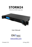
Philips luminous textile with
System integration
© Royal Philips Electronics N.V. 2014
2
System integration April 2014
Luminous textile panel
Contents
Document information........................................................................................................................................... 5
1.Introduction........................................................................................................................................................... 6
1.1General........................................................................................................................................ 6
1.2 Application examples................................................................................................................. 6
1.2.1 Change content on entry............................................................................................... 6
1.2.2 Integrate in a demonstration setup.............................................................................. 6
1.2.3 Different layers of content............................................................................................. 6
1.2.4 Play with cameras........................................................................................................... 6
1.2.5 Play with depths and resolutions................................................................................... 6
1.2.6 Integration with functional lighting and building management systems.................. 6
1.2.7 Video Jockey with luminous textile............................................................................... 7
1.2.8 Use the luminous textile to display parts of a computer screen............................... 7
1.2.9 Custom created interactivity, straight from your computer..................................... 7
2. Validity of this document................................................................................................................................ 8
3. Connection to a luminous textile installation..................................................................................... 9
3.1 Physical connection.................................................................................................................... 9
3.2 LAN / subnet settings................................................................................................................. 9
4. Luminous textile panel settings............................................................................................................... 10
4.1 Home page................................................................................................................................ 11
4.2 Settings page (control section)............................................................................................... 12
4.3 Settings page (LTP info section)............................................................................................. 13
4.4 Applications page..................................................................................................................... 14
4.5 Lighting integration page........................................................................................................ 15
5. Triggering the on board playback system.......................................................................................... 16
5.1 Default control.......................................................................................................................... 16
5.2 HTTP GET command set....................................................................................................... 17
5.3 TCP commands........................................................................................................................ 19
5.3.1 Example of TCP integration using the Pharos control system................................ 21
5.4 Philips Dynalite Dynet commands......................................................................................... 23
5.5 Philips Color Kinetics Keypad integration............................................................................. 25
5.5.1 Philips Color Kinetics Ethernet Controller Keypad.................................................. 25
5.5.2 Philips Color Kinetics Remote Keypad....................................................................... 27
6. Integration via streaming protocols....................................................................................................... 29
6.1Art-Net...................................................................................................................................... 30
6.1.1Introduction................................................................................................................... 30
6.1.2Limitations.................................................................................................................... 30
6.1.3 DMX table..................................................................................................................... 30
6.1.4 Mapping order............................................................................................................... 31
6.1.5 Mapping examples........................................................................................................ 32
6.1.6 Universes per panel...................................................................................................... 33
6.1.7 Selecting Art-Net mode, Addressing and binding IP address................................... 34
6.1.8 Testing and troubleshooting........................................................................................ 35
Luminous textile panel
System integration April 2014
3
6.2KiNET........................................................................................................................................ 37
6.2.1Introduction................................................................................................................... 37
6.2.2Limitations.................................................................................................................... 37
6.2.3 DMX table..................................................................................................................... 37
6.2.4 Mapping order............................................................................................................... 38
6.2.5 Mapping examples........................................................................................................ 39
6.2.6 Ports per panel.............................................................................................................. 40
6.2.7 Selecting KiNET mode................................................................................................. 41
6.2.8 Testing and troubleshooting........................................................................................ 42
7. Default settings................................................................................................................................................. 45
8.Contact.................................................................................................................................................................. 46
4
System integration April 2014
Luminous textile panel
Document information
Info
Content
Title
System integration
Date
March 2014
Security
The attached material and the information contained herein are proprietary to Large Luminous
Surfaces, Philips Lighting BV. Copying, reproduction, adaptation, modification or dissemination
in whole or part is not permitted without written permission from Large Luminous Surfaces,
Philips Lighting.
Contact
address
Large Luminous Surfaces, Philips Lighting BV
High Tech Campus 27
5600 AE Eindhoven, the Netherlands
Email: [email protected] or [email protected]
Website: www.largeluminoussurfaces.com
Luminous textile panel
System integration April 2014
5
1. Introduction
1.1
General
The Luminous textile panel can easily be integrated with various control and building management systems. This allows for
the luminous textile to become integrated with (available) control systems, reactive to sensors or interactive to cameras
or other advanced sensors. This document will describe the various alternatives and protocols the luminous textile panel
supports.
It is expected that the reader of this document is acquainted with system integration, lighting control systems and has
knowledge about the installation and use of the luminous textile.
Note that advanced skills and experience might be required to create certain integrated applications. These installations are
mostly performed by a partner or installer who has programming skills to build the application to customers’ needs. There
are various companies that can perform this task, please contact us and we can help you in finding a suitable partner to
perform this task for you.
1.2
Application examples
There is a wide variety of integration options possible to increase the value of your luminous textile application. Below are
some examples how system integration might be of use for reactive or interactive installations.
Please feel free to contact us for more information at [email protected]
1.2.1 Change content on entry
Imagine walking into a room and the surfaces comes to life!
Using a simple ceiling mount sensor to detect your presence from a control system like Dynalite, it can easily be linked to
luminous textile.
1.2.2 Integrate in a demonstration setup
Have a luminous textile panel in your showroom? Ensure all your demonstrations to customers are perfectly synchronized,
every time. The luminous textile can easily be linked with Crestron / AMX / Pharos and other control systems which are
typically used in this type of environment
1.2.3 Different layers of content
Do you like your content, but would you like to use multiple movies at the same time? Or adjust colors in real time, set
transparency, zoom and much, much more? Media servers like Pandoras box from Coolux, Green Hippo systems or MA
lighting controls can natively control our luminous textile panels.
1.2.4 Play with cameras
Would you like to link a camera to the panels? Not to ‘just’ show video, but maybe for some face recognition? Or track
where on the panel the person is watching? There are standard solutions available who offer this type of features, such as
Pandoras box media server from Coolux.
1.2.5 Play with depths and resolutions
The luminous textile is a great solution to provide ambient atmosphere. But what if you sometimes need to provide
information too? Using media servers like those mentioned above, you can seamlessly link high resolution projection with
our low resolution ambient lighting, all from a single controller.
1.2.6 Integration with functional lighting and building management systems
You’ve got a Dynalite or other system installed to control your functional lighting? Why not ensure that the luminous textile
turns on and off at the right times? Save energy by ensuring the panel is not on longer than is necessary.
6
System integration April 2014
Luminous textile panel
1.2.7 Video Jockey with luminous textile
For the perfect rhythmic mix of music and content, and have real time control to adapt to the crowd's wishes, software
programs such as Madrix or other media servers can control directly via the controller connected to our panels. A great
way to create a good party atmosphere.
1.2.8 Use the luminous textile to display parts of a computer screen
Got some great graphics program on your computer that you would like to see in real time on your panels? There are offthe-shelf systems available to link your video content to our panels. Composite,VGA or DVI? No problem, just convert it to
display on our panels using Philips Color Kinetics Video System Manager, Artistic Licence DVNET or media converter.
1.2.9 Custom created interactivity, straight from your computer
For those who are comfortable with writing software, a streaming protocol that our panels support can easily be integrated.
Interactive solutions, ever changing content, content created by users worldwide, the only limit is your imagination…
Inspired, but don’t know where to start? Please feel free to contact us for more information at
[email protected]
Luminous textile panel
System integration April 2014
7
2. Validity of this document
The mentioned integration options and syntax are relevant for luminous textile firmware version 2.5.x.
Please note that previous releases might function in slightly different ways or not support all features.
If your installation is firmware version 1.x.x, please contact support.
If your installation is firmware version 2.x.x, please upgrade to the latest available firmware version.
Firmware is integrated in the content manager software package and available on our website. If your installation is a newer
firmware version, please check for an updated document on system integration on the website.
See www.largeluminoussurfaces.com for more information.
8
System integration April 2014
Luminous textile panel
3. Connection to a luminous textile installation
3.1
Physical connection
All supported system integration to a luminous textile installation is via the ethernet port of the panel(s).
Even though the physical interface on the panel (RJ45, 100Base-T, Auto-MDIX capability) might allow for direct interfacing, it
is advised to always connect the panels to a network switch. Additionally it is advised to have at least 1 spare port on your
switch available to connect a PC for commissioning, programming and possible troubleshooting purposes.
Please note that a WiFi connection between 3rd party devices and the luminous textile network is possible, but might affect
the reliability of the connection and therefore triggering/control.
Master
Slave
from
3rd party
device
LAN
for commissioning,
programming, troubleshooting
Figure 1: Default setup with luminous panels.
3.2
LAN / subnet settings
It is strongly advised to test your integration by connecting your devices on the same LAN, within the same subnet. Large
Luminous Surfaces can only give support on system integration between 3rd party devices and the panels when devices are in
the same subnet.
Once this is working, IT departments can help you to route the required signal through their network.
Luminous textile panels are shipped with DHCP enabled. On the panels webserver (administrator settings page), the panel
can be given a fixed IP address/subnet mask / gateway if required. Please ensure to save settings.
Note:
• Many control systems require you to work with a known IP address of the panel. Using a fixed IP address
(or DHCP reservation) is therefore advised when making an integrated solution.
• After changing a physical connection (from one DHCP server to another), a reboot of the panel is required.
The IP addresses of a panel can be set on the
Settings > Control > Network settings section.
See Chapter 4 for more information or consult the Content Manager manual.
Luminous textile panel
System integration April 2014
9
4. Luminous textile panel settings
Each luminous textile panel has an integrated webserver which allows for control and configuration of the luminous textile
using your favorite web-browser on your PC or mobile system via user friendly websites.
IP addresses of the panel can be found using the Content Manager Software. Simply discover the network and click the
“open control page” icon from the Content Manager software, or type the IP address of a panel in a browser to open
the page and browse to the required page to adjust settings. As the firmware updating is done via the Content Manager
Software too, please ensure that you are using version 2.5.x of the software.
Note:
• Please check www.largeluminoussurfaces.com/software for the latest release.
• Please refer to the Content Manager Software manual for more information about using the software.
www.largeluminoussurfaces.com/content/downloads-luminous-textile
Figure 2: Content Manager software - Surface configurator.
In this document textual links are used and written in bold.
These textual links are the buttons or icons you need to press or select to get to the relevant selection.
Please see the following screenshots to see what the interface screens look like.
10
System integration April 2014
Luminous textile panel
4.1
Home page
A
B
C
D
E
1
2
F
4
3
Figure 3: Default setup with luminous panels.
A
User manual link: Shows all product related documents
B
Application: Shows the available applications. Default login: admin/admin
C
Scheduler: Shows you the currently active schedule
D
Settings: Default login: admin/admin
E
Home: Default landing page / standard control page
F
Control buttons > Previous playlist, Play, Stop, Next playlist
1
Current playing album and album selection (show *streaming* in streaming mode)
2
Home > select Album
3
Home > select Playlist (any of the thumbnails)
4
Play mode: Indicates the play and operation mode for this panel
Luminous textile panel
System integration April 2014
11
4.2
Settings page (control section)
A
B
C
D
E
F
5
6
7
8
9
Figure 4: Settings page (Control section).
12
A
User manual link: Shows all product related documents
B
Application: Shows the available applications. Default login: admin/admin
C
Scheduler: Shows you the currently active schedule
D
Settings: Default login: admin/admin
E
Home: Default landing page / standard control page
F
Settings > Control buttons > Previous playlist, Play, Stop, Pause, Identify, Next playlist
5
Settings > Control
6
Settings > Control > Advanced Controls
7
Settings > Control > General Settings
8
Settings > Control > Network Settings
9
Settings > Control > Save as default settings
System integration April 2014
Luminous textile panel
4.3
Settings page (LTP info section)
A
B
C
D
E
F
11
10
12
13
Figure 5: Settings page (LTP info section).
A
User manual link: Shows all product related documents
B
Application: Shows the available applications. Default login: admin/admin
C
Scheduler: Shows you the currently active schedule
D
Settings: Default login: admin/admin
E
Home: Default landing page / standard control page
F
Settings > Control buttons > Previous playlist, Play, Stop, Pause, Identify, Next playlist
10
Settings > LTP info
11
Settings > LTP info > statistics
12
Settings > LTP info > status
13
Settings > LTP info > system
Luminous textile panel
System integration April 2014
13
4.4
Applications page
A
B
C
D
E
F
14
Figure 6: Applications page.
14
A
User manual link: Shows all product related documents
B
Application: Shows the available applications. Default login: admin/admin
C
Scheduler: Shows you the currently active schedule
D
Settings: Default login: admin/admin
E
Home: Default landing page / standard control page
F
Control buttons > Previous playlist, Play, Stop, Next playlist
14
Applications > Lighting integration app
System integration April 2014
Luminous textile panel
4.5
Lighting integration page
A
B
C
D
E
F
15
16
17
18
19
20
Figure 7: Lighting integration app.
A
User manual link: Shows all product related documents
B
Application: Shows the available applications. Default login: admin/admin
C
Scheduler: Shows you the currently active schedule
D
Settings: Default login: admin/admin
E
Home: Default landing page / standard control page
F
Control buttons > Previous playlist, Play, Stop, Next playlist
15
Applications > Lighting integration app > Dynalite settings
16
Applications > Lighting integration app > Philips Color Kinetics Keypad settings
17
Applications > Lighting integration app > Philips Color Kinetics remote Keypad settings
18
Applications > Lighting integration app > Streaming settings
19
Applications > Lighting integration app > Art-Net Settings
20
Applications > Lighting integration app > Save settings
Luminous textile panel
System integration April 2014
15
5. Triggering the on board playback system
5.1
Default control
The luminous textile panel features a per panel integrated playback system. This allows for playback of different types of
content, arranged as one or more playlists per album, and of course multiple albums can be present.
To give easy control of this to users, a user friendly built-in website has been integrated.
When having a multiple panel installation, the ‘master panel’ is in charge of all the panels in this network. In a single network
only one master panel should be present, see installation instructions for more details.
For a multipanel installation, only the website of the master panel needs to be accessed for controlling the complete
luminous textile installation.
This page can be accessed / found by:
• Using the DiscoverMe LTP app on a smart device on the same network
• Discovering panels on the network using the Content Manager software
• Browsing to the (known from installer) IP address of the master panel using a favorite web-browser on your PC or
mobile system.
See our documentation at www.largeluminoussurfaces.com/content/downloads-luminous-textile for more information.
On the homepage simply click a playlist to start
Home > select Playlist
Or to select a different album
Home > select Album
You can use the control buttons for additional control
Control buttons > Previous playlist, Play, Stop, Next playlist
If you are not sure about the IP address of the panel, browse to
Settings > LTP info > system
and locate ‘ip_address’ in the menu.
16
System integration April 2014
Luminous textile panel
5.2
HTTP GET command set
The built-in website uses ‘HTTP GET’ commands for control. Any external device sending the same commands can be used
to control the luminous textile. For example, this can be a manual action in a browser, or a custom script on a PC.
The supported messages are equal to the common commands available via:
Home > select Playlist
Home > select Album
Control buttons > Previous playlist, Play, Stop, Next playlist
Settings > Control > Advanced Controls (operation mode only)
Settings > Control > General Settings (brightness only)
Settings > Control buttons > Previous playlist, Play, Stop, Pause, Identify, Next playlist
The syntax to recall those actions can be found in Figure 8:
In all examples the IP address of the master panel is
IP address: 192.168.2.100
In this example the panel has two albums uploaded via the Content Manager software,
Album_01.lcf
Album_02.lcf
Note:
• Many control systems will require you to work with a known IP address of the panel. Using a fixed IP address (or
DHCP reservation) is therefore advised when making an integrated solution.
• After changing a physical connection (from one DHCP server to another), a reboot of the panel is required.
• The Album name is entered in the Content Converter (3) section of the Content Manager software
Luminous textile panel
System integration April 2014
17
Type
Command (description)
The following commands are typically only sent to the master panel.
The master panel addresses the change to all slave panels.
Start
http://192.168.2.100/control.php?command=Start
Start to play the first playlist in current album (player mode only)
Stop
http://192.168.2.100/control.php?command=Stop
Stop playback. LTP goes to stand by (player mode only)
Next
http://192.168.2.100/control.php?command=Next
Play next playlist in the current album. If the last playlist is playing, continue playing this last playlist (player
mode only)
Previous
http://192.168.2.100/control.php?command=Prev
Play previous playlist in the current album. If the first playlist is playing, continue playing this first playlist
(player mode only)
Pause
http://192.168.2.100/control.php?command=Pause
Pause / Resume current image (player mode only)
GoTo
http://192.168.2.100/control.php?command=Playlist&playlist=2
Start to play playlist 2 in the current album. If no such playlist exists, the panel will ignore the command.
Note that playlist 0 is the first playlist in the file (player mode only)
GoTo
http://192.168.2.100/control.php?command=File&file=Album_01.lcf&playlist=2
Start to play playlist 2 in the ‘Album_01’ album. Album name is case sensitive. Note that playlist 0 is the
first playlist in the file (player mode only)
Intensity
http://192.168.2.100/control.php?command=Brightness&value=90
Set the intensity of the luminous textile in a 0-100% range (value can be 0-100). Note that 0 is minimum
intensity, not off (player mode only)
The following commands are valid for the addressed panel only.
Send to master and slave panels if required.
Identify
http://192.168.2.100/control.php?command=Identify
Show the test image on the panel. Only the addressed panel will react. (player mode only)
Streaming
http://192.168.2.100/control.php?command=Streaming
Change the luminous textile to streaming mode. (to be used from player mode)
Player
http://192.168.2.100/control.php?command=Player
Change the luminous textile to player mode, and start the playlist last playing.
If there was no playlist playing, the first playlist in the last used album (to be used from streaming mode)
Intensity
http://192.168.2.100/control.php?command=Brightness&value=90
Set the intensity of the luminous textile in a 0-100% range (value can be 0-100). Note that 0 is minimum
intensity, not off (streaming mode only)
Figure 8: HTTP integration command set.
Note:
• Please ensure the following commands are sent to the (IP address of) the master panel of your installation
• All commands are case sensitive.
18
System integration April 2014
Luminous textile panel
5.3
TCP commands
Many control systems can output TCP commands, but no HTTP GET commands.
However, a HTTP GET command is sent over the network as a TCP command.
In all examples the IP address of the master panel is
IP address: 192.168.2.100
In all examples the IP address of the 3rd party controller or PC is
IP address: 192.168.2.99
In this example the panel has two albums uploaded via the Content Manager software,
Album_01.lcf
Album_02.lcf
Note:
• Many control systems will require you to work with a known IP address of the panel. Using a fixed IP address
(or DHCP reservation) is therefore advised when making an integrated solution.
• After changing a physical connection (from one DHCP server to another), a reboot of the panel is required.
• The Album name is entered in the Content Converter (step 3) section of the Content Manager software.
Luminous textile panel
System integration April 2014
19
Type
Command (description)
The following commands are typically only sent to the master panel.
The master panel addresses the change to all slave panels.
Start
GET /control.php?command=Start HTTP/1.1\r\nHost: 192.168.2.99\r\n\r\n
Start to play the first playlist in current album (player mode only)
Stop
GET /control.php?command=Stop HTTP/1.1\r\nHost: 192.168.2.99\r\n\r\n
Stop playback. LTP goes to stand by (player mode only)
Next
GET /control.php?command=Next HTTP/1.1\r\nHost: 192.168.2.99\r\n\r\n
Play next playlist in the current album. If the last playlist is playing, continue playing this last playlist (player
mode only)
Previous
GET /control.php?command=Prev HTTP/1.1\r\nHost: 192.168.2.99\r\n\r\n
Play previous playlist in the current album. If the first playlist is playing, continue playing this first playlist
(player mode only)
Pause
GET /control.php?command=Pause HTTP/1.1\r\nHost: 192.168.2.99\r\n\r\n
Pause / Resume current image (player mode only)
GoTo
GET /control.php?command=Playlist&playlist=2 HTTP/1.1\r\nHost: 192.168.2.99\r\n\r\n
Start to play playlist 2 in the current album. If no such playlist exists, the panel will ignore the command.
Note that playlist 0 is the first playlist in the file (player mode only)
GoTo
GET /control.php?command=File&file=Album_01.lcf&playlist=2 HTTP/1.1\r\nHost: 192.168.2.99\r\n\r\n
Start to play playlist 2 in the ‘Album_01’ album. Album name is case sensitive. Note that playlist 0 is the
first playlist in the file (player mode only)
Intensity
GET /control.php?command=Brightness&value=90 HTTP/1.1\r\nHost: 192.168.2.99\r\n\r\n
Set the intensity of the luminous textile in a 0-100% range (value can be 0-100, the example use “90”).
Note that 0 is minimum intensity, not off (player mode only)
The following commands are valid for the addressed panel only.
Send to master and slave panels if required.
Identify
http://192.168.2.100/control.php?command=Identify HTTP/1.1\r\nHost: 192.168.2.99\r\n\r\n
Show the test image on the panel. Only the addressed panel will react. (player mode only)
Streaming
GET /control.php?command=Streaming HTTP/1.1\r\nHost: 192.168.2.99\r\n\r\n
Change the luminous textile to streaming mode. (to be used from player mode)
Player
GET /control.php?command=Player HTTP/1.1\r\nHost: 192.168.2.99\r\n\r\n
Change the luminous textile to player mode and start the playlist last playing.
If there was no playlist playing, the first playlist in the last used album (to be used from streaming mode)
Intensity
GET /control.php?command=Brightness&value=90 HTTP/1.1\r\nHost: 192.168.2.99\r\n\r\n
Set the intensity of the luminous textile in a 0-100% range (value can be 0-100, the example use “90”).
Note that 0 is minimum intensity, not off (streaming mode only)
Figure 9: TCP integration command set.
Note:
• Please ensure the following commands are sent to the (IP address of) the master panel of your installation
• All commands are case sensitive.
20
System integration April 2014
Luminous textile panel
5.3.1 Example of TCP integration using the Pharos control system
Pharos equipment is often used in Philips projects. The Pharos system can be easily used to trigger the luminous textile.
Within Pharos, ensure the controller’s ethernet port (i.e. Bus 1) is opened on TCP port 80. See Figure 10:
Figure 10: Setting up Pharos controller ethernet port.
Note:
• You might get a warning that this setting can clash with the setting in the Pharos device built-in web server. This
Pharos web server setting can be changed in the ‘controller config’ tab if required, but experience shows this is not
required in all cases.
In the 'trigger' tab, ensure that the Ethernet output is sending to the luminous textile master panel’s IP address, and the
protocol and bus are correctly specified.
For the trigger data field, click edit button and use the exact syntax as described in Chapter 5.3. See Figure 11.
Luminous textile panel
System integration April 2014
21
Figure 11: Sending triggers to luminous textile.
Note:
• Please ensure the following commands are sent to the (IP address of) the master panel of your installation
• All commands are case sensitive.
Contact support if you would like to receive this test file.
22
System integration April 2014
Luminous textile panel
5.4
Philips Dynalite Dynet commands
Philips Dynalite is an advanced system for office and retail lighting control. The luminous textile can be controlled by recalling
presets to an area, where the presets will correspond to playlists.
A Philips Dynalite ethernet gateway is required to control the luminous textile.
Note that integration takes place with Philips Dynalite's Dynet commands (ethernet based), not with the RS485 based Philips
Dynalite protocol.
Philips Dynalite equipment, including the ethernet gateway, should be configured before use. It will not integrate with the
luminous textile ‘out of the box’. The luminous textile will listen to a subset containing some logical messages (mentioned in
Figure 12) for a specified area.
As both systems can be freely configured, please note the area and port number.
Gateway configuration: Port number: [0-65535] Area number:[0-255] UDP mode
________________
________________
{note the used port number here}
{note the used area number here}
On the luminous textile, these parameters can be specified on
Applications > Lighting integration app> Dynalite settings
Note:
• The communication will happen via a UDP broadcast from the gateway on its subnet, please ensure the luminous
textile and gateway share the same subnet.
• Please contact your Philips Dynalite support for question on setting up the Philips Dynalite system.
Luminous textile panel
System integration April 2014
23
Type
Dynalite
Stop
Off
Sync
Area
3rd byte
Opcode
5th byte
6th byte
7th byte
Checksum
1C
Area
(xx)
04
(xx)
(xx)
Join
Checksum
(xx)
(xx)
Join
Checksum
(xx)
(xx)
Join
Checksum
00
00
Join
Checksum
Join
Checksum
Start to play the first playlist in current album (player mode only)
Dim Down
Decrement
1C
Area
(xx)
05
Decrease intensity by 10% (player mode only)
Dim Up
Increment
1C
Area
(xx)
06
Increase intensity by 10% (player mode only)
Intensity
Area to level
1C
Area
(level)
79
Set the intensity of the luminous textile in a 1-100% range
(value between 01-FF, where FF is minimum intensity, 01 is maximum intensity)
Playlist 1
Preset 1
1C
Area
(xx)
00
(xx)
00
Start to play playlist 0 in the current album. If no such playlist exists, the panel will ignore the command.
Note that playlist 0 is the first playlist in the file (player mode only)
Playlist 2
Preset 2
1C
Area
(xx)
01
(xx)
00
Join
Checksum
00
Join
Checksum
00
Join
Checksum
00
Join
Checksum
00
Join
Checksum
00
Join
Checksum
00
Join
Checksum
01
Join
Checksum
01
Join
Checksum
01
Join
Checksum
02
Join
Checksum
Start to play playlist 1 in the current album. (see preset 1 notes)
Playlist 3
Preset 3
1C
Area
(xx)
02
(xx)
Start to play playlist 2 in the current album. (see preset 1 notes)
Playlist 4
Preset 4
1C
Area
(xx)
03
(xx)
Start to play playlist 3 in the current album. (see preset 1 notes)
Playlist 5
Preset 5
1C
Area
(xx)
0A
(xx)
Start to play playlist 4 in the current album. (see preset 1 notes)
Playlist 6
Preset 6
1C
Area
(xx)
0B
(xx)
Start to play playlist 5 in the current album. (see preset 1 notes)
Playlist 7
Preset 7
1C
Area
(xx)
0C
(xx)
Start to play playlist 6 in the current album. (see preset 1 notes)
Playlist 8
Preset 8
1C
Area
(xx)
0D
(xx)
Start to play playlist 7 in the current album. (see preset 1 notes)
Playlist 9
Preset 9
1C
Area
(xx)
00
(xx)
Start to play playlist 8 in the current album. (see preset 1 notes)
Playlist 10
Preset 10
1C
Area
(xx)
01
(xx)
Start to play playlist 9 in the current album. (see preset 1 notes)
…
Playlist 16
Preset 16
Playlist 17
Preset 17
1C
Area
(xx)
0D
…
(xx)
Start to play playlist 15 in the current album. (see preset 1 notes)
1C
Area
(xx)
00
(xx)
Start to play playlist 16 in the current album. (see preset 1 notes)
…
…
…
…
Figure 12: Dynalite integration command set.
Note:
• (xx)
24
ignored byte
• Area use area in both luminous textile and Dynalite system, note only 1 area can be used
• … logical continuation of the Opcode (4th byte) and preset bank (6th byte)
System integration April 2014
Luminous textile panel
5.5
Philips Color Kinetics Keypad integration
5.5.1 Philips Color Kinetics Ethernet Controller Keypad
When a Philips Color Kinetics Ethernet Controller Keypad is connected to the luminous textile network, it can be used to
control the luminous textile.
Please note that Philips Color Kinetics hardware has, by default, a fixed IP address in the 10.x.x.x / 255.0.0.0 range. Please
use the ‘QuickPlay Pro‘ software to alter this.
Note:
• Use either the Controller Keypad, or the Remote Keypad (5.5.2) in a single installation.
No additional configurations are required to the panel.
Color Kinetics operates by default on port 6041. If needed, you can change this on the luminous textile panel in the Lighting
Integration App.
Applications > Lighting integration app> Philips Color Kinetics Keypad settings
For more information on the Philips Color Kinetics Controller Keypad, please visit
http://www.colorkinetics.com
http://www.colorkinetics.com/ls/controllers/enetkeypad/
http://www.colorkinetics.com/ls/controllers/quickplaypro/
Luminous textile panel
System integration April 2014
25
Type
Command (description)
Show 1
Start to play playlist 0 in the current album. If no such playlist exists, the panel will ignore the command.
Note that playlist 0 is the first playlist in the file (player mode only)
Show 2
Start to play playlist 1 in the current album. If no such playlist exists, the panel will ignore the command.
Note that playlist 0 is the first playlist in the file (player mode only)
Show 3
Start to play playlist 2 in the current album. If no such playlist exists, the panel will ignore the command.
Note that playlist 0 is the first playlist in the file (player mode only)
Show 4
Start to play playlist 3 in the current album. If no such playlist exists, the panel will ignore the command.
Note that playlist 0 is the first playlist in the file (player mode only)
Show 5
Start to play playlist 4 in the current album. If no such playlist exists, the panel will ignore the command.
Note that playlist 0 is the first playlist in the file (player mode only)
Show 6
Start to play playlist 5 in the current album. If no such playlist exists, the panel will ignore the command.
Note that playlist 0 is the first playlist in the file (player mode only)
Show 7
Start to play playlist 6 in the current album. If no such playlist exists, the panel will ignore the command.
Note that playlist 0 is the first playlist in the file (player mode only)
Show 8
Start to play playlist 7 in the current album. If no such playlist exists, the panel will ignore the command.
Note that playlist 0 is the first playlist in the file (player mode only)
Dim up
Increase intensity by 10% (player mode only)
Dim down
Decrease intensity by 10% (player mode only)
Off
Stop playback. LTP goes to stand by (player mode only)
Figure 13: Philips Color Kinetics Ethernet Controller Keypad integration functionality.
1
5
2
6
3
7
4
8
Show buttons
Dimmer controls
OFF
Turns all show lights off
Figure 14: Philips Color Kinetics Ethernet Controller Keypad.
26
System integration April 2014
Luminous textile panel
5.5.2 Philips Color Kinetics Remote Keypad
When the Philips Color Kinetics Remote Keypad app is installed on an Apple or Android smart device, and the device is
connected to the luminous textile network it can be used to control the luminous textile.
Note:
• Use either the Controller Keypad (5.5.1), or the Remote Keypad in a single installation
Color Kinetics operates by default on port 6041. If needed, you can change this on the luminous textile panel in the Lighting
Integration App.
Applications > Lighting integration app> Philips Color Kinetics Remote Keypad settings
For more information on the Philips Color Kinetics Remote Keypad, please visit
http://www.colorkinetics.com
http://www.colorkinetics.com/ls/controllers/remotekeypad/
Luminous textile panel
System integration April 2014
27
Type
Command (description)
Show 1
Start to play playlist 0 in the current album. If no such playlist exists, the panel will ignore the command.
Note that playlist 0 is the first playlist in the file (player mode only)
Show 2
Start to play playlist 1 in the current album. If no such playlist exists, the panel will ignore the command.
Note that playlist 0 is the first playlist in the file (player mode only)
Show 3
Start to play playlist 2 in the current album. If no such playlist exists, the panel will ignore the command.
Note that playlist 0 is the first playlist in the file (player mode only)
Show 4
Start to play playlist 3 in the current album. If no such playlist exists, the panel will ignore the command.
Note that playlist 0 is the first playlist in the file (player mode only)
Show 5
Start to play playlist 4 in the current album. If no such playlist exists, the panel will ignore the command.
Note that playlist 0 is the first playlist in the file (player mode only)
Show 6
Start to play playlist 5 in the current album. If no such playlist exists, the panel will ignore the command.
Note that playlist 0 is the first playlist in the file (player mode only)
Show 7
Start to play playlist 6 in the current album. If no such playlist exists, the panel will ignore the command.
Note that playlist 0 is the first playlist in the file (player mode only)
Show 8
Start to play playlist 7 in the current album. If no such playlist exists, the panel will ignore the command.
Note that playlist 0 is the first playlist in the file (player mode only)
Dim up
Increase intensity by 10% (player mode only)
Dim down
Decrease intensity by 10% (player mode only)
Off
Stop playback. LTP goes to stand by (player mode only)
Figure 15: Philips Color Kinetics Remote Keypad integration functionality.
1
5
2
6
3
7
4
8
Show buttons
Dimmer controls
Off
Turns all show lights off
Figure 16: Philips Color Kinetics Remote Keypad.
28
System integration April 2014
Luminous textile panel
6. Integration via streaming protocols
The luminous textile can be used in a “streaming mode”. In this mode, the panel reacts to “DMX over Ethernet” messages
for pixel precise control. The protocols supported are Art-Net and KiNET, and are further explained in next paragraphs.
The panel can be activated to listen to incoming messages if the operation mode is changed to “Streaming”.
This can be done via the settings page
Settings > Control > Advanced Controls
or via an external trigger (see Chapter 5.2/ 5.3)
The panel does support operation using the onboard playback system or the streaming input at different moments in time.
Switching between the two operating modes can take up to 10 seconds. During the switching time, the visual output of the
panels might be affected.
Changing the operation mode on the master panel will automatically change the operation mode of all slave panels in the
system. If “streaming” should be the default operation mode at startup, please press the “save as default” button.
Settings > Control > Save as default settings
Note that the “Save as default” action only applies to the specific panel the action is performed on. To set 'Streaming' as the
default mode for a multi-panel installation, “save as default” action should be performed on all individual panels.
Luminous textile panel
System integration April 2014
29
6.1
Art-Net
6.1.1 Introduction
The Art-Net protocol is developed by Artistic Licence, and published in the public domain. Visit http://www.artisticlicence.com
for more details on the specification. As the protocol is available in the public domain, a wide range of companies is creating
Art-Net compatible controllers.
The luminous textile supports Art-Net 3 standard. (@ max 50 fps). The panel is compatible with controllers outputting ArtNet version 1, 2 or 3.
6.1.2 Limitations
Notes:
• Panel name and IP address can only be set on the luminous textile panel.
• Attempting to change the name via a 3rd party device or software might lose the connection with the panel. A reboot
of the panel and 3rd party device or software might be required to discover the panel again.
• The maximum supported frame rate is 50 fps.
• On universes and subnets that integrate luminous textile, no Art-Net data intended for other devices should be
present.
• Panels will be discovered both in streaming and player mode, regardless of KiNET or Art-Net mode
• Latency <<2 frames by definition. Exact latency on request, please contact support.
6.1.3 DMX table
Controlling the luminous textile is done per node (“pixel”).
For every node, 3 DMX channels are used:
1st channel Red intensity
2nd channel Green intensity
3rd channel Blue intensity
The “brightness level” on the panel itself can still be used for master intensity. This means that even for low light outputs the
full resolution can be used.
Use
Settings > Control > General Settings > Brightness level
or an external trigger (see Chapter 5.2/ 5.3)
30
System integration April 2014
Luminous textile panel
6.1.4 Mapping order
The order of the nodes follows “reading order”. From left to right, top to bottom, node 1, node 2, etc. This continues for a
complete number of lines to fill a universe (max 170 nodes).
After this the first node (by definition on the left of the panel) is the first node in the next universe. This continues till the
complete panel is filled. The last universe might be identical to the previous universe, or contain fewer lines.
If a panel is used in landscape, please check that the rotation of the panel on the settings page is properly set.
Settings > Control > General Settings > Panel orientation
This will ensure that the height (h) and width (w) of the panel are consistent with the physical installation.
The panel's height and width can be found by dividing the physical dimension of the panels (in cm) by 6, or by looking it up in
Settings > LTP info > status > panel_width
Settings > LTP info > status > panel_height
Visually the patching can be represented as in Figure 17:
(w)= width in nodes (or width in cm / 6)
(h) = height in nodes (or height in cm / 6)
(a) = number of rows within a “full” universe (depending on w)
(b) = number of rows in the panel's last universe (depending on h)
Width (w)
(b)
(a)
Height (h)
(b)
(a)
(a)
Height (h)
(a)
(a)
(a)
Width (w)
Figure 17: Visual representation of the patching.
(a) depends on the panel's width and can be found in Figure 18.
(b) can be calculated by taking (h) and subtracting (a) until this ends up at a number equal or between 0 and (a)-1.
W
12
13
14
15
16-17
18
19-21
22-24
25-28
29-34
35-42
43-56
57-72
a
14
13
12
11
10
9
8
7
6
5
4
3
2
Figure 18: Panel width vs. lines per universe.
Luminous textile panel
System integration April 2014
31
6.1.5 Mapping examples
Example 1: Panel dimension 216 cm height by 120 cm width (portrait installation)
1: Define width and height
Option 1: (w)= width in nodes (or width in cm / 6)
(w)= 120/6 = 20 nodes
(h) = height in nodes (or height in cm / 6)
(h) = 216/6 = 36 nodes
Option 2:
Go to Setting -> LTP info page and look under system.
Settings > LTP info > status > panel_width
Settings > LTP info > status > panel_height
2: Identify (a) in Figure 18: panel width vs. lines per universe.
(a) = 8
3: Calculate b
(b) = subtracting (a) from (h) until this ends up at a number equal or between 0 and (a)-1.
(b) = (36) – 8-8-8-8 = 4
This panel has 4 universes each of 8x20 nodes, and the 5th universe of 4x20 nodes.
Example 2: Panel dimensions 102 cm height by 180 cm width (landscape installation)
1: Ensure the panel orientation is set to 90’
Settings > Control > General Settings > Panel orientation
2: Define width and height
Option 1: (w)= width in nodes (or width in cm / 6)
(w)= 180/6 = 30 nodes
(h) = height in nodes (or height in cm / 6)
(h) = 102/6 = 17 nodes
Option 2:
Go to Setting -> LTP info page and look under system.
Settings > LTP info > status > panel_width
Settings > LTP info > status > panel_height
3: Identify (a) in Figure 18: panel width vs. lines per universe.
(a) = 5
4: Calculate b
(b) = subtracting (a) from (h) until this ends up at a number equal or between 0 and (a)-1.
(b) = (17) – 5-5-5 = 3
This panel has 3 universes each of 5x30 nodes, and the 4th universe of 3x30 nodes.
32
System integration April 2014
Luminous textile panel
6.1.6 Universes per panel
Typically a panel will require multiple universes. See Figure 19: Universes required per panel.
(w)
12
13
14
15
16-17
18
19-21
22-24
25-28
29-34
35-42
43-56
57-72
(a)
14
13
12
11
10
9
8
7
6
5
4
3
2
(h)
12
1
1
1
2
2
2
2
2
2
3
3
4
6
13
1
1
2
2
2
2
2
2
3
3
4
5
7
14
1
2
2
2
2
2
2
2
3
3
4
5
7
15
2
2
2
2
2
2
2
3
3
3
4
5
8
16
2
2
2
2
2
2
2
3
3
4
4
6
8
17-18
2
2
2
2
2
2
3
3
3
4
5
6
9
19-20
2
2
2
2
2
3
3
3
4
4
5
7
10
21-22
2
2
2
2
3
3
3
23-24
2
2
2
3
3
3
3
25-26
2
2
3
3
3
3
4
27
2
3
3
3
3
3
4
28
2
3
3
3
3
4
4
29-30
3
3
3
3
3
4
4
31-32
3
3
3
3
4
4
4
33
3
3
3
3
4
4
5
34-36
3
3
3
4
4
4
5
37-40
3
3
4
4
4
5
5
40
3
4
4
4
4
5
5
41-42
3
4
4
4
5
5
6
43-44
4
4
4
4
5
5
6
45
4
4
4
5
5
5
6
46-48
4
4
4
5
5
6
6
49-50
4
4
5
5
5
6
7
51-52
4
4
5
5
6
6
7
53-54
4
5
5
5
6
6
7
55
4
5
5
5
6
7
7
56
4
5
5
6
6
7
7
57-60
5
5
5
6
6
7
8
61-63
5
5
6
6
7
7
8
64
5
5
6
6
7
8
8
65
5
5
6
6
7
8
9
66
5
6
6
6
7
8
9
67-70
5
6
6
7
7
8
9
71-72
6
6
6
7
8
8
9
Figure 19: Universes required per panel.
Luminous textile panel
System integration April 2014
33
6.1.7 Selecting Art-Net mode, Addressing and binding IP address
To activate streaming, set the panel to streaming mode:
Settings > Control > Advanced Controls
or via an external trigger (see Chapter 5.2/ 5.3)
To activate Art-Net as the streaming protocol, set the panel to streaming mode and select Art-Net:
Applications > Lighting integration app > Streaming settings
Press "save settings" after changing the streaming protocol.
The Art-Net specification has a limit of receiving a maximum of 4 universes per IP address.
To enable a device to receive more than 4 universes, “binding IP addresses” are introduced in the standard.
As a luminous textile panel can contain up to 10 universes, it requires 2 binding IP addresses (additional to the luminous
textile panel’s IP address).
Fill in valid values for the binding IP addresses; ensure that the IP addresses are available on your network.
The binding IP addresses receive data only, no additional settings such as subnet are required.
Applications > Lighting integration app > Art-Net Settings
Press "save settings" after changing values.
The start universe for a panel can be set under:
Applications > Lighting integration app > Art-Net Settings
As the panel is using Art-Net 3, there are three fields to set:
Net, Subnet, and Universe
Notes:
• The first universe is universe 00.
• All universes will be automatically incremented to the number of universes the panel consumes.
• All universes in a (binding) IP address will always be in the same net / subnet.
• (If necessary the last universe in a subnet might remain unused, and addressing will jump to the next subnet – universe
00 to continue for this binding IP address)
• All nodes in each universe will start from DMX address 001.
Examples of jumps in universe addressing can be seen in Figure 20.
Panel universes count
9
9
9
9
6
6
Start universe (panel IP)
2nd universe (panel IP)
3rd universe (panel IP)
4th universe (panel IP)
00-00-00
00-00-01
00-00-02
00-00-03
00-00-12
00-00-13
00-00-14
00-00-15
00-00-10
00-00-11
00-00-12
00-00-13
00-00-07
00-00-08
00-00-09
00-00-10
00-00-10
00-00-11
00-00-12
00-00-13
00-00-11
00-00-12
00-00-13
00-00-14
5th universe (binding IP 1)
6th universe (binding IP 1)
7th universe (binding IP 1)
8th universe (binding IP 1)
00-00-04
00-00-05
00-00-06
00-00-07
00-01-00
00-01-01
00-01-02
00-01-03
00-01-00*)
00-01-01
00-01-02
00-01-03
00-00-11
00-00-12
00-00-13
00-00-14
00-00-14
00-00-15
00-01-00*)
00-01-01
9th universe (binding IP 2)
10th universe (binding IP 2)
00-00-08
00-00-09
00-01-04
00-01-05
00-01-04
00-01-05
00-01-00*)
00-01-01
* jumps in the addressing, to have all universes in a (binding) IP address in the same net / subnet.
Figure 20: Universe addressing logic, examples.
34
System integration April 2014
Luminous textile panel
6.1.8 Testing and troubleshooting
If the image expected appears upside down, please go to "panel orientation" and change the rotation by 180°.
If a scrambled image shows, please go to "panel orientation" and check the rotation.
Settings > Control > General Settings > Panel orientation
Testing is optional, but advised as this is an easy way to check your installation.
Artistic Licence offers a software tool “DMX Workshop”. This software tool will allow checking if panels are correctly
setup. Additionally it provides some tests to output data to specific channels to verify your setup.
Download and install the software:
http://www.artisticlicence.com/WebSiteMaster/Software/dmxworkshopsetup.msi
Check application note 045 if you encounter issues with starting up the software:
http://www.artisticlicence.com/WebSiteMaster/App%20Notes/appnote045.pdf
Open the software and ensure you select the correct network interface.
You should see a window similar as in Figure 21:
Figure 21: DMX- Workshop menu.
Press "node list" and press "refresh". Unfold where necessary. You should discover all your connected panels (both panel IP
and populated binding IP’s) and the universe it is set to. See Figure 22.
Luminous textile panel
System integration April 2014
35
Figure 22: DMX-Workshop node list.
If required, you can control the installation by using the "Dynamic" function under "Transmit DMX". See Figure 23:
Note
• Panels will be discovered both in streaming and player mode, regardless of KiNET or Art-Net mode.
Figure 23: DMX-Workshop transmit dynamic DMX.
For further information about DMX workshop, please consult Artistic Licence via www.artisticlicence.com.
36
System integration April 2014
Luminous textile panel
6.2
KiNET
6.2.1 Introduction
The KiNET protocol is developed by Color Kinetics (now Philips Color Kinetics). It’s a proprietary protocol.
Contact [email protected] for information on licensing.
The luminous textile supports the KiNET v2, the ‘port out’ version.
6.2.2 Limitations
Notes:
• Panel name and IP address can only be set on the luminous textile panel.
• Attempting to change the name via a 3rd party device or software like Quick Play Pro might lose the connection with
the panel. A reboot of the panel and 3rd party device or software might be required to discover the panel again.
• The maximum supported frame rate is 50 fps
• Panels will be discovered both in streaming and player mode, regardless of KiNET or Art-Net mode
• Latency <<2 frames by definition. Exact latency on request, please contact support
6.2.3 DMX table
Controlling the luminous textile is done per node (“pixel”).
For every node, 3 DMX channels are used:
1st channel Red intensity
2nd channel Green intensity
3rd channel Blue intensity
The “brightness level” on the panel itself can still be used for master intensity. This means that even for low light outputs the
full resolution can be used.
Settings > Control > General Settings > Brightness level
or via an external trigger (see Chapter 5.2/ 5.3)
Luminous textile panel
System integration April 2014
37
6.2.4 Mapping order
A complete luminous textile panel will act like a power supply and a number of ports with nodes.
The order of the nodes follows “reading order”. From left to right, top to bottom, node 1, node 2, etc. This continues for a
complete number of lines to fill a port (max 170 nodes).
After this the first node (by definition on the left of the panel) is the first node in the next port. This continues till the
complete panel is filled. The last port might be identical to the previous port, or contain fewer lines.
If a panel is used in landscape, please check that the rotation of the panel on the settings page is properly set.
Settings > Control > General Settings > Panel orientation
This will ensure that the height (h) and width (w) of the panel are consistent with the physical installation.
The panel’s height and width can be found by dividing the physical dimension of the panels (in cm) by 6, or by looking it up in
Settings > LTP info > status > panel_width
Settings > LTP info > status > panel_height
Visually the patching can be represented as in Figure 24:
(w)= width in nodes (or width in cm / 6)
(h) = height in nodes (or height in cm / 6)
(a) = number of rows within a “full” port (depending on w)
(b) = number of rows in the panel's last port (depending on h)
Width (w)
(b)
(a)
Height (h)
(b)
(a)
(a)
Height (h)
(a)
(a)
(a)
Width (w)
Figure 24: Visual representation of the patching.
(a) depends on the panel's width and can be found in Figure 25.
(b) can be calculated by taking (h) and subtracting (a) until this ends up at a number equal or between 0 and (a)-1.
W
12
13
14
15
16-17
18
19-21
22-24
25-28
29-34
35-42
43-56
57-72
a
14
13
12
11
10
9
8
7
6
5
4
3
2
Figure 25: Panel width vs. lines per port.
38
System integration April 2014
Luminous textile panel
6.2.5 Mapping examples
Example 1: Panel dimension 216 cm height by 120 cm width (portrait installation)
4: Define width and height
Option 1: (w)= width in nodes (or width in cm / 6)
(w)= 120/6 = 20 nodes
(h) = height in nodes (or height in cm / 6)
(h) = 216/6 = 36 nodes
Option 2:
Go to Setting -> LTP info page and look under system.
Settings > LTP info > status > panel_width
Settings > LTP info > status > panel_height
5: Identify (a) in Figure 25: panel width vs. lines per port.
(a) = 8
6: Calculate b
(b) = subtracting (a) from (h) until this ends up at a number equal or between 0 and (a)-1.
(b) = (36) – 8-8-8-8 = 4
This panel has 4 ports each of 8x20 nodes, and the 5th port of 4x20 nodes.
Example 2: Panel dimensions 102 cm height by 180 cm width (landscape installation)
1: Ensure the panel orientation is set to 90’
Settings > Control > General Settings > Panel orientation
2: Define width and height
Option 1: (w)= width in nodes (or width in cm / 6)
(w)= 180/6 = 30 nodes
(h) = height in nodes (or height in cm / 6)
(h) = 102/6 = 17 nodes
Option 2:
Go to Setting -> LTP info page and look under system.
Settings > LTP info > status > panel_width
Settings > LTP info > status > panel_height
3: Identify (a) in Figure 25: panel width vs. lines per port.
(a) = 5
4: Calculate b
(b) = subtracting (a) from (h) until this ends up at a number equal or between 0 and (a)-1.
(b) = (17) – 5-5-5 = 3
This panel has 3 ports each of 5x30 nodes, and the 4th port of 3x30 nodes.
Luminous textile panel
System integration April 2014
39
6.2.6 Ports per panel
Typically a panel will require multiple ports. See Figure 26: Number of ports per panel.
(w)
12
13
14
15
16-17
18
19-21
22-24
25-28
29-34
35-42
43-56
57-72
(a)
14
13
12
11
10
9
8
7
6
5
4
3
2
(h)
12
1
1
1
2
2
2
2
2
2
3
3
4
6
13
1
1
2
2
2
2
2
2
3
3
4
5
7
14
1
2
2
2
2
2
2
2
3
3
4
5
7
15
2
2
2
2
2
2
2
3
3
3
4
5
8
16
2
2
2
2
2
2
2
3
3
4
4
6
8
17-18
2
2
2
2
2
2
3
3
3
4
5
6
9
19-20
2
2
2
2
2
3
3
3
4
4
5
7
10
21-22
2
2
2
2
3
3
3
23-24
2
2
2
3
3
3
3
25-26
2
2
3
3
3
3
4
27
2
3
3
3
3
3
4
28
2
3
3
3
3
4
4
29-30
3
3
3
3
3
4
4
31-32
3
3
3
3
4
4
4
33
3
3
3
3
4
4
5
34-36
3
3
3
4
4
4
5
37-40
3
3
4
4
4
5
5
40
3
4
4
4
4
5
5
41-42
3
4
4
4
5
5
6
43-44
4
4
4
4
5
5
6
45
4
4
4
5
5
5
6
46-48
4
4
4
5
5
6
6
49-50
4
4
5
5
5
6
7
51-52
4
4
5
5
6
6
7
53-54
4
5
5
5
6
6
7
55
4
5
5
5
6
7
7
56
4
5
5
6
6
7
7
57-60
5
5
5
6
6
7
8
61-63
5
5
6
6
7
7
8
64
5
5
6
6
7
8
8
65
5
5
6
6
7
8
9
66
5
6
6
6
7
8
9
67-70
5
6
6
7
7
8
9
71-72
6
6
6
7
8
8
9
Figure 26: Number of ports per panel.
40
System integration April 2014
Luminous textile panel
6.2.7 Selecting KiNET mode
To activate streaming, set the panel to streaming mode:
Settings > Control > Advanced Controls
or via an external trigger (see Chapter 5.2/ 5.3)
To activate KiNET as the streaming protocol, set the panel to streaming mode and select KiNET:
Applications > Lighting integration app > Streaming settings
Press "save settings" after changing the streaming protocol.
The PDS which will be simulated by the luminous textile has the number of ports as specified in paragraph 6.2.6.
Notes:
• The first port is port 1.
• All nodes in each port will start from DMX address 001.
• All ports will be automatically incremented to the number of ports the panel consumes.
• The PDS is simulated with the number of ports it actually consumes.
Luminous textile panel
System integration April 2014
41
6.2.8 Testing and troubleshooting
If the image expected appears upside down, please go to "panel orientation" and change the rotation by 180°.
If a scrambled image shows, please go to "panel orientation" and check the rotation.
Settings > Control > General Settings > Panel orientation
Testing is optional, but advised as this is an easy way to check your installation.
Philips Color Kinetics offers a software tool “QuickPlay Pro” for this. This software tool will allow checking if panels are
correctly setup. Additionally it provides some tests to output data to specific channels to verify your setup.
http://www.colorkinetics.com/ls/controllers/quickplaypro/
Download and install the software:
http://www.colorkinetics.com/support/addressing/
Open the software.
If you have multiple network interfaces active: Use Tools > Option > Network to select the correct network interface.
You should see a window similar as in Figure 27:
Figure 27: QuickPlay Pro main window.
Use the "controller" drop-down menu to check if you have discovered all your panels.
Note
• Panels will be discovered both in streaming and player mode, regardless of KiNET or Art-Net mode
42
System integration April 2014
Luminous textile panel
Select “All supplies” in the "controller" drop-down menu and “ all ports” to control your full installation. See Figure 28.
Figure 28: QuickPlay Pro main window, Controller selection changed.
Luminous textile panel
System integration April 2014
43
Use the "Test Channels" feature to test individual nodes. See Figure 29.
Figure 29: QuickPlay Pro Test Channels window.
For further information about QuickPlay Pro, please check the manual:
http://www.colorkinetics.com/support/userguides/Addressing_Configuration_Guide_QPP.pdf
or contact Philips Color Kinetics support at [email protected]
44
System integration April 2014
Luminous textile panel
7. Default settings
Operation: Player Mode: Panel orientation:
Network Settings: Player
Standalone
0 degrees
DHCP on
Dynalite settings Port number:
Dynalite settings Area:
[empty]
[empty]
Philips Color Kinetics Ethernet Controller Keypad settings
Port number:
6041
Philips Color Kinetics Remote Keypad settings
Port number:
6041
If DHCP is changed; the following defaults apply
Change to DCHP off:
static IP address:
10.11.11.10
Subnet mask:
[empty] (255.0.0.0 is used)
Gateway:[empty]
If Operation is changed, the following defaults apply
Steaming protocol:
KiNET
If Streaming protocol is changed, the following defaults apply
Default Art-Net address: Net: 0 Subnet: 0 Universe: 0
Binding IP address 1: 2.66.19.79
Binding IP address 2: 2.66.19.80
Luminous textile panel
System integration April 2014
45
8. Contact
Large Luminous Surfaces, Philips Lighting B.V
High Tech Campus 27
5600 AE Eindhoven, the Netherlands
Email: [email protected] or [email protected]
Website: www.largeluminoussurfaces.com
46
System integration April 2014
Luminous textile panel
Philips reserves the right to make design and specification changes
for product improvement without prior notice.
Trademarks are the property of Royal Philips Electronics or their respective owners.
2014© Royal Philips Electronics.
All rights reserved.