1
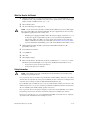
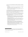
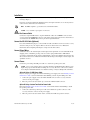
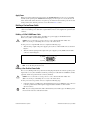
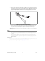
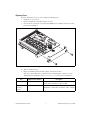
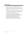
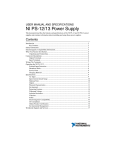
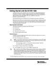
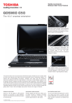
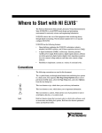
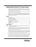
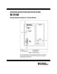
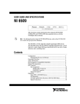
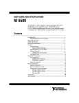
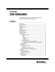
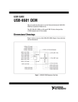
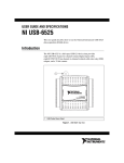
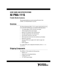
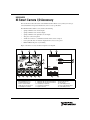
USER GUIDE NI Smart Camera I/O Accessory This document describes the features of the NI Smart Camera I/O Accessory, what you need to get started, installation and operation instructions, and accessory specifications. The NI Smart Camera I/O Accessory features the following: • Spring terminals for two isolated inputs • Spring terminals for two isolated outputs • Spring terminals for the quadrature encoder inputs • Two power connection options • An RS-232 connector to communicate with the smart camera serial port • User-replaceable fuses for isolated outputs, RS-232, and accessory power • Built-in DIN rail clips for easy mounting Figure 1 shows the accessory circuit board parts locator diagram. 1 2 3 12 13 14 4 NATIONAL INSTRUMENTS NI SMART CAMERA I/O ACCESSORY 15 5 18 11 1 2 3 4 5 6 10 9 8 Camera D-SUB Connector RS-232 D-SUB Connector 24 VDC D-SUB Connector Power In Selection Switch 24VDC Two-Position Connector Isolated Output 1 Terminals 7 6 7 8 9 10 11 12 17 Isolated Output 0 Terminals Quadrature Encoder Phase B Terminals Quadrature Encoder Phase A Terminals Isolated Input 1 Terminals Isolated Input 0 Terminals Spare Power Fuse 16 13 14 15 16 17 18 Power Fuse Spare RS-232 Fuse RS-232 Fuse Isolated Output 0 Fuse Spare Isolated Output Fuses Isolated Output 1 Fuse Figure 1. Front and Back Views of the NI Smart Camera I/O Accessory Circuit Board What You Need to Get Started ❑ NI Smart Camera I/O Accessory kit, which includes the accessory, 15-pin D-SUB female to 15-pin D-SUB male cable, 2 m (part number 197817-02), and two-position header connector (Wago part number 734-102, available from www.wago.com) ❑ NI 17xx Smart Camera ❑ One of the following power supply options: Caution Use the smart camera only with a 24 VDC, UL listed, limited power source (LPS) supply. The power supply will bear the UL listed mark, LPS. The power supply must also meet any safety and compliance requirements for the country of use. – NI desktop power supply (part number 780237-01) and power supply cord. Refer to ni.com for the power supply cord part number specific to your region and ordering information. – Any 24 VDC, +20%/–15% (IEC 1311) power supply, such as the PS-5 power supply (part number 778805-90), and custom power cable. Refer to the Building a Custom Power Cable section for information about building a power cable for the NI Smart Camera I/O Accessory. ❑ (Optional) NI 9-pin female D-SUB to 9-pin female D-SUB null modem RS-232 cable (part number 182238-xx) ❑ 0.125 in. flathead screwdriver ❑ 12–28 AWG wire ❑ Wire cutter ❑ Wire insulation stripper ❑ Related documentation—The following documents, available from ni.com/manuals, contain information you may find helpful as you set up and use the NI Smart Camera I/O Accessory: – Getting Started with the NI 17xx Smart Camera – NI 17xx Smart Camera User Manual Safety Information Caution The following paragraphs contain important safety information you must follow when installing and operating the device. Do not operate the device in a manner not specified in this document. Misuse of the device can result in a hazard. You can compromise the safety protection built into the device if the device is damaged in any way. If the device is damaged, return it to National Instruments (NI) for repair. Do not substitute parts or modify the device except as described in this document. Use the device only with the chassis, devices, accessories, and cables specified in the installation instructions. You must have all covers and filler panels installed during operation of the device. Do not operate the device in an explosive atmosphere or where there may be flammable gases or fumes. If you must operate the device in such an environment, it must be in a suitably rated enclosure. If you need to clean the device, use a soft, nonmetallic brush. Make sure that the device is completely dry and free from contaminants before returning it to service. NI Smart Camera I/O Accessory User Guide 2 ni.com Operate the device only at or below Pollution Degree 2. Pollution is foreign matter in a solid, liquid, or gaseous state that can reduce dielectric strength or surface resistivity. The following is a description of pollution degrees: • Pollution Degree 1 means no pollution or only dry, nonconductive pollution occurs. The pollution has no influence. • Pollution Degree 2 means that only nonconductive pollution occurs in most cases. Occasionally, however, a temporary conductivity caused by condensation must be expected. • Pollution Degree 3 means that conductive pollution occurs, or dry, nonconductive pollution occurs that becomes conductive due to condensation. You must insulate signal connections for the maximum voltage for which the device is rated. Do not exceed the maximum ratings for the device. Do not install wiring while the device is live with electrical signals. Do not remove or add connector blocks when power is connected to the system. Avoid contact between your body and the connector block signal when hot swapping devices. Remove power from signal lines before connecting them to or disconnecting them from the device. Operate the device at or below the installation category1 marked on the hardware label. Measurement circuits are subjected to working voltages2 and transient stresses (overvoltage) from the circuit to which they are connected during measurement or test. Installation categories establish standard impulse withstand voltage levels that commonly occur in electrical distribution systems. The following is a description of installation categories: 1 2 3 • Installation Category I is for measurements performed on circuits not directly connected to the electrical distribution system referred to as MAINS3 voltage. This category is for measurements of voltages from specially protected secondary circuits. Such voltage measurements include signal levels, special equipment, limited-energy parts of equipment, circuits powered by regulated low-voltage sources, and electronics. • Installation Category II is for measurements performed on circuits directly connected to the electrical distribution system. This category refers to local-level electrical distribution, such as that provided by a standard wall outlet (for example, 115 AC voltage for U.S. or 230 AC voltage for Europe). Examples of Installation Category II are measurements performed on household appliances, portable tools, and similar devices. • Installation Category III is for measurements performed in the building installation at the distribution level. This category refers to measurements on hard-wired equipment such as equipment in fixed installations, distribution boards, and circuit breakers. Other examples are wiring, including cables, bus bars, junction boxes, switches, socket outlets in the fixed installation, and stationary motors with permanent connections to fixed installations. • Installation Category IV is for measurements performed at the primary electrical supply installation (<1,000 V). Examples include electricity meters and measurements on primary overcurrent protection devices and on ripple control units. Installation categories, also referred to as measurement categories, are defined in electrical safety standard IEC 61010-1. Working voltage is the highest rms value of an AC or DC voltage that can occur across any particular insulation. MAINS is defined as a hazardous live electrical supply system that powers equipment. Suitably rated measuring circuits may be connected to the MAINS for measuring purposes. © National Instruments Corporation 3 NI Smart Camera I/O Accessory User Guide Installation To get started with the NI 17xx Smart Camera I/O Accessory, complete the following steps while referring to Figure 1. If you have not already installed the NI Smart Camera and required software, refer to Getting Started with the NI 17xx Smart Camera for instructions. Note For EMC compliance, operate this device with shielded cables. Caution Never touch the exposed pins of connectors. Connect the Camera Cable Connect the 15-pin D-SUB female to 15-pin D-SUB male cable to the CAMERA connector on the accessory and to the POWER-I/O connector on the smart camera. Refer to the NI 17xx Smart Camera User Manual for the POWER-I/O connector pinout and signal information. Connect the RS-232 Cable (Optional) For serial communication purposes, connect an RS-232 cable to the RS-232 connector on the accessory and to the serial port on your computer. Refer to the NI 17xx Smart Camera User Manual for information about configuring and using the serial port of the smart camera. Connect Signal Wires Connect the wires to the isolated input, isolated output, and/or quadrature encoder terminal blocks by stripping 1/4 in. of insulation, pressing on the lever of the spring terminal with a small flathead screwdriver, and inserting the wire into the terminal. Figure 1 shows the terminal locations. Refer to the NI 17xx Smart Camera User Manual for information about using isolated inputs, isolated outputs, and quadrature encoders. Connect Power Connect the power using a D-SUB power cable or a custom two-position power cable. Caution Do not connect input voltages greater than 24 VDC to the NI Smart Camera I/O Accessory. Input voltages greater than 24 VDC can damage the accessory, all devices connected to it, and the host computer. National Instruments is not liable for damage or injury resulting from such misuse. Option A: Using a D-SUB Power Cable If you are using a power supply other than the NI desktop power supply, refer to the Building a 15-Pin D-SUB Power Cable section for information about building a custom 15-pin D-SUB power cable. 1. Connect the power supply cord to the 24VDC D-SUB connector on the accessory and to the connector on the power supply. 2. Move the power in selection switch “up”, towards the 24VDC D-SUB connector. Option B: Using a Custom Two-Position Power Cable Refer to the Building a Two-Position Power Cable section for information about building a custom two-position power cable. 1. Connect the custom two-position power cable to the 24VDC two-position connector on the accessory and to the connector on the power supply. 2. Move the power in selection switch “down”, towards the 24VDC two-position connector. NI Smart Camera I/O Accessory User Guide 4 ni.com Apply Power When power is first applied to the smart camera, the POWER LED flashes red for one second while internal systems power up. The POWER LED then lights green when power is correctly wired to the smart camera. If the smart camera does not power up, check all connections and the power in selection switch position, then check the power fuse, as described in the Fuses section. Building a Custom Power Cable If you are using a power supply other than the NI desktop power supply, you must build your own power cable. You can build a power cable with a 15-pin D-SUB connector or the supplied two-position header connector. Building a 15-Pin D-SUB Power Cable You can connect any 24 VDC, +20%/–15% (IEC 1311) power supply to the NI Smart Camera I/O Accessory with a custom D-SUB power cable. Caution Do not connect the accessory power to a source other than 24 VDC +20%/–15% (IEC 1311). Doing so could damage the accessory or the smart camera. To wire power to a 15-pin D-SUB connector, complete the following steps. 1. Wire the voltage output of the power supply to pin 5 (+24 V) on the D-SUB connector, shown in Figure 2. 2. Wire the common signal (ground) output of the power supply to pin 15 (COM) on the D-SUB connector, shown in Figure 2. 11 15 (COM) 10 6 5 (+24 V) 1 Figure 2. 15-Pin D-SUB Pinout Note Leave all other pins unconnected. Building a Two-Position Power Cable The accessory kit ships with a two-position header that plugs directly into the 24V two-position power input on the accessory. You can build a custom two-position power cable with 16–18 AWG wire, ferrules (optional), and the two-position header connector (included). Caution Do not connect the accessory power to a source other than 24 VDC +20%/–15% (IEC 1311). Doing so could damage the accessory or the smart camera. To wire power to the two-position connector, complete the following steps. 1. Using wire strippers, carefully remove the insulation from each (16–18 AWG) wire to be connected to the two-position header. The length of stripped insulation should be 4.3 mm–4.6 mm (0.17 in.–0.18 in.). Note If you are using stranded wire, NI recommends that you use ferrules (up to 16 AWG) to protect the wires from wear due to vibration and strain. © National Instruments Corporation 5 NI Smart Camera I/O Accessory User Guide 2. Wire the voltage output of the 24 VDC +20%/–15% (IEC 1311) power supply to the main voltage input on the two-position connector as shown in Figure 3. Insert a small flathead screwdriver into the square opening. Using the screwdriver as a lever to open the clamp, insert the wire into the spring terminal opening. Remove the screwdriver to securely clamp the wire. COM +24 VDC Figure 3. Power Two-Position Header Wiring Diagram 3. Wire the common signal (ground) output of the power supply to the COM signal input on the two-position connector, shown in Figure 3, using the same technique described in step 2. Additional power two-position header connectors (part number 734-102) can be ordered from Wago at www.wago.com. Fuses The NI Smart Camera I/O Accessory has four replaceable fuses. Refer to Figure 1 for the fuse locations. • The power fuse (2 A), protects the NI Smart Camera from overcurrent through the +24 VDC connectors. • The other three fuses (200 mA), protect the smart camera from overcurrent through isolated output 0, isolated output 1, or protect the computer from overcurrent through the ground on the RS-232 connector. Testing Fuses You can check the continuity of the fuse with a handheld DMM. To do this, you must remove the side panel, as described in steps 1 through 4 of the Replacing Fuses section. NI Smart Camera I/O Accessory User Guide 6 ni.com Replacing Fuses To replace a blown fuse on the accessory, complete the following steps. 1. Unplug the accessory power. 2. Remove all signal wires and cables from the accessory. 3. Unscrew the two screws from a side panel with a Phillips head screwdriver and remove the side panel as shown in Figure 4. M S C I A N I/O L A N EN O M RA TI U M E Y A R A R N ST T C SSO IN AR CE Figure 4. Removing the Circuit Board 4. Slide the circuit board out. 5. Replace the blown fuse while referring to Figure 1 for the fuse location. Spare fuses can be found next to each fuse location as shown in Figure 1. You also can order additional fuses from Littelfuse at www.littelfuse.com or from electronics distributors. Fuse Littelfuse Part Number Description Power 0448002 2A, 125V lead-free very fast-acting NANO2 subminiature ceramic surface mount fuse, 6.10 × 2.69 mm Iso Out 0, Iso Out 1, RS-232 0448.200 200mA, 125V lead-free very fast-acting NANO2 subminiature ceramic surface mount fuse, 6.10 × 2.69 mm © National Instruments Corporation 7 NI Smart Camera I/O Accessory User Guide Specifications This section lists the specifications of the NI Smart Camera I/O Accessory. These specifications are typical at 25 °C, unless otherwise noted. Note Refer to the NI 17xx Smart Camera User Manual for specifications about signals. Power Requirement Supply voltage .......................................................24 VDC +20%/–15% (IEC 1311) Current requirement ...............................................Refer to the specification for your NI Smart Camera Physical Dimensions ............................................................8.712 cm × 8.509 cm × 4.445 cm (3.43 in. × 3.35 in. × 1.75 in.) Weight ....................................................................98.1 g (3.46 oz) Spring terminal blocks ...........................................6, 2 positions per block Wire gauge .....................................................12–28 AWG wire Camera connector ..................................................15-pin D-SUB male connector RS-232 connector ..................................................9-pin D-SUB male connector 24VDC connector ..................................................15-pin D-SUB female connector Environmental The NI Smart Camera I/O Accessory is intended for indoor use only. Operating temperature ...........................................0 to 55 °C Storage temperature ...............................................–20 to 70 °C Humidity ................................................................10 to 90%, noncondensing Pollution Degree ....................................................2 Approved at altitudes up to 2,000 m. Safety The NI Smart Camera I/O Accessory is designed to meet the requirements of the following standards of safety for electrical equipment for measurement, control, and laboratory use: • IEC 61010-1, EN 61010-1 • UL 61010-1, CSA 61010-1 Note For UL and other safety considerations, refer to the product label, or visit ni.com/ certification, search by model number or product line, and click the appropriate link in the Certification column. NI Smart Camera I/O Accessory User Guide 8 ni.com CE Compliance The NI Smart Camera I/O Accessory meets the essential requirements of applicable European Directives, as amended for CE marking, as follows: • 2006/95/EC; Low-Voltage Directive (safety) • 2004/108/EC; Electromagnetic Compatibility Directive (EMC) Note Refer to the Declaration of Conformity (DoC) for this product for any additional regulatory compliance information. To obtain the DoC for this product, visit ni.com/certification, search by model number or product line, and click the appropriate link in the Certification column. Compliance with EU Directives Users in the European Union (EU) should refer to the Declaration of Conformity (DoC) for information1 pertaining to the CE marking. Refer to the Declaration of Conformity (DoC) for this product for any additional regulatory compliance information. To obtain the DoC for this product, visit ni.com/ certification, search by model number or product line, and click the appropriate link in the Certification column. Environmental Management National Instruments is committed to designing and manufacturing products in an environmentally responsible manner. NI recognizes that eliminating certain hazardous substances from our products is beneficial not only to the environment but also to NI customers. For additional environmental information, refer to the NI and the Environment Web page at ni.com/environment. This page contains the environmental regulations and directives with which NI complies, as well as other environmental information not included in this document. Waste Electrical and Electronic Equipment (WEEE) EU Customers At the end of their life cycle, all products must be sent to a WEEE recycling center. For more information about WEEE recycling centers and National Instruments WEEE initiatives, visit ni.com/environment/weee.htm. ⬉ᄤֵᙃѻક∵ᶧࠊㅵ⧚ࡲ⊩ ˄Ё RoHS˅ Ёᅶ᠋ National Instruments ヺড়Ё⬉ᄤֵᙃѻકЁ䰤ࠊՓ⫼ᶤѯ᳝ᆇ⠽䋼ᣛҸ (RoHS)DŽ ݇Ѣ National Instruments Ё RoHS ড়㾘ᗻֵᙃˈ䇋ⱏᔩ ni.com/environment/rohs_chinaDŽ (For information about China RoHS compliance, go to ni.com/environment/rohs_china.) 1 The CE marking Declaration of Conformity contains important supplementary information and instructions for the user or installer. © National Instruments Corporation 9 NI Smart Camera I/O Accessory User Guide Where to Go for Support The National Instruments Web site is your complete resource for technical support. At ni.com/support you have access to everything from troubleshooting and application development self-help resources to email and phone assistance from NI Application Engineers. A Declaration of Conformity (DoC) is our claim of compliance with the Council of the European Communities using the manufacturer’s declaration of conformity. This system affords the user protection for electronic compatibility (EMC) and product safety. You can obtain the DoC for your product by visiting ni.com/certification. If your product supports calibration, you can obtain the calibration certificate for your product at ni.com/calibration. National Instruments corporate headquarters is located at 11500 North Mopac Expressway, Austin, Texas, 78759-3504. National Instruments also has offices located around the world to help address your support needs. For telephone support in the United States, create your service request at ni.com/support and follow the calling instructions or dial 512 795 8248. For telephone support outside the United States, contact your local branch office: Australia 1800 300 800, Austria 43 662 457990-0, Belgium 32 (0) 2 757 0020, Brazil 55 11 3262 3599, Canada 800 433 3488, China 86 21 5050 9800, Czech Republic 420 224 235 774, Denmark 45 45 76 26 00, Finland 358 (0) 9 725 72511, France 01 57 66 24 24, Germany 49 89 7413130, India 91 80 41190000, Israel 972 3 6393737, Italy 39 02 41309277, Japan 0120-527196, Korea 82 02 3451 3400, Lebanon 961 (0) 1 33 28 28, Malaysia 1800 887710, Mexico 01 800 010 0793, Netherlands 31 (0) 348 433 466, New Zealand 0800 553 322, Norway 47 (0) 66 90 76 60, Poland 48 22 3390150, Portugal 351 210 311 210, Russia 7 495 783 6851, Singapore 1800 226 5886, Slovenia 386 3 425 42 00, South Africa 27 0 11 805 8197, Spain 34 91 640 0085, Sweden 46 (0) 8 587 895 00, Switzerland 41 56 2005151, Taiwan 886 02 2377 2222, Thailand 662 278 6777, Turkey 90 212 279 3031, United Kingdom 44 (0) 1635 523545 NI Smart Camera I/O Accessory User Guide 10 ni.com National Instruments, NI, ni.com, and LabVIEW are trademarks of National Instruments Corporation. Refer to the Terms of Use section on ni.com/legal for more information about National Instruments trademarks. Other product and company names mentioned herein are trademarks or trade names of their respective companies. For patents covering National Instruments products/technology, refer to the appropriate location: Help»Patents in your software, the patents.txt file on your media, or the National Instruments Patent Notice at ni.com/patents. © 2008 National Instruments Corporation. All rights reserved. 372578A-01 Aug08