1
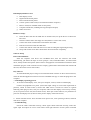
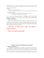
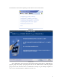
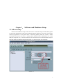
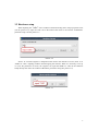
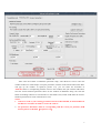
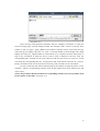
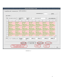
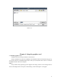
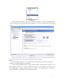
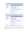
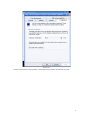
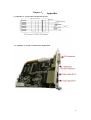
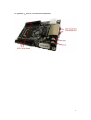
User’s Manual
Led Manager
2011-8-8
Table of Contents
Chapter 1. Introduction
Dear friends:
Thank you again for choosing our products and it’s really our honor to have your support in
our development.
In order to keep the our brand screens working well under the right operation, we briefly
summarize the application and items to attention as follows for your references. Users must take
these items to heart seriously before installing and debugging the screen.
2
LED display Hardware List:
a. LED display screen
b. Signal chord between panels
c. Power chord between panels
d. Control system-sender card (to be installed inside the computer)
e. Receive card(to be installed inside of each panel)
f. Computer mainframe (including DVI signal output and port)
g. Other accessories
Hardware Setup:
h. Insert the DVI card into the AGD slot on mother board, set up the drivers’ software for
DVI card.
i. Insert the sender card in the empty PCI slot(if there is such a card or slot)
j. Connect the sender card and DVI card with the DVI cable.
k. Link the control wire with the USB cable
l. Connect the network cable with the receive card according the engineering drawing
m. Set up and test the screen after check all the chord connection completely.
Software Setup
DVI card installation:
Insert the Graphics card driver into CD-ROM drive, then the software will install
automatically, just follow the steps as screen prompts. First, Install DirectX8.1, and then install
driver, finally install control panel. (Please refer to ATI graphics card installation manual for detail
installation progress. If the card not from our company, please fellow the manual book which with
the card, and set the card as clone mode).
Play software
To install dedicated player of large screen and LED studio software or other control software,
insert the attached application software CD into CD-ROM and copy or install all programs to the
computer.
☆ LED display operating process
1、 To switch on LED display: First, start your computer, second, switch on LED display.
Connect all equipments into power (ensure that input voltage is in line with requirement of
product), switch on LED screen (It shows that LED screen is turned on if there is regional
flickering when plug in).Next, start your computer, make sure that display card is set up correctly
(if not, no picture can be seen, that is black screen). Then open control software, set parameters of
pixel size and display area (It doesn’t affect picture display of the LED screen).
2、Switch off LED screen: Turn off LED screen power first, close operating software, and then
shut down computer.
☆ Troubleshooting
Check all cables connected correctly; check signal chord connected correctly, make sure
signal input and output on receive card connect with right interface. Check system connected
3
correctly (please refers to system connection manual), make sure all the software install
completely, which include Graphics card set up (please refer to Graphics card set up manual), and
operating software installation.
☆ Notice:
1. Fellow with “user manual’ in steps:
2. Moisture proof; Humidity requirements: maximum working temperature should be less
than 92% relative humidity;
3. Reasonable temperature: working environment temperature -20°C≤t≤80°C
Storing environment temperature -40°C≤t≤60°C
Notice: to get a good working environment for LED display, make sure that thermal
insulation system and heat removal system can be designed and be installed during
installation of LED display.
3、Requirement of power supply:
Voltage of power supply of LED display: 220V±10% frequency: 50HZ±5%, safe and
reliable access to the ground, reliable isolation between ground wire and zero line, input power far
from large power electric appliance. Any questions during the installation and operating please
read our manual accordingly or contact us directly. In order to maintain and use a high-quality
display, your suggestion or comment welcomed.
4 、
One piece of main power cable can support 4
cabinets at most.
The screen must be grounded .
5、
Chapter 2. Software Installation and Uninstall
2.1 Software Installation
“LED Studio’ can be easily installed, as shown below: put the “LED Studio” installation CD
into the CD-ROM, The Installation Menu will automatically pop up. (If not, then select this CDROM; double click it with your mouse) Then select “Install LED Studio” to start the Installation
Guide, as shown in Figure 2-1. After that, simply follow the instruction on the screen. Note: This
software is protected by a serial number. Please enter the correct serial number in order to process
4
the installation. Please ask the products provider for the correct serial number.
Picture 2-1
Picture 2-2
After “LED Studio” software has been successfully installed, there will be a “LED Software”
program group in the [Start] / [Program], then move to the “LED Software” under this program
group, click to start. Also there will be a “LED Studio” short-cup on your desktop: as figure 2-3.
Also, you can start the program by double click on the icon.
5
Picture 2-3
2.2 Uninstall
“LED Studio” software provide an auto-uninstall function, for your convenience to delete all
“LED Studio” files, program groups and short-cuts, users can either select “Delete LED Studio”
under the “LED Software” group, or go to the [Control Panel], select [add/delete program] to
undergo quick uninstall. (Uninstall window as show in Figure 2-4), now select “Automatic” can
delete all files, program groups and short-cuts.
Picture 2-4
6
Chapter 3. Software and Hardware Setup
3.1 Software Setup
Please check whether the setup of ATI card correct or not before usage of LED studio (please
see the Usage Introduction of ATI for the install and setup of ATI drive). Turn on the screen power
when the preparation is ready, then there is territorial glittering when the screen is instant
electrified which shows the screen is working. Next double click the LED Studio icon on the
desk(see the picture 2-3) to start the software, then click the menu to choose Software Setup to
enter the window of software setup(see the picture 3-1),then set up the size of window.
Picture 3-1
7
3.2 Hardware setup
When inputting the “zdec” in the window of Software Setup, there will pop up Enter code
(see the picture 3-2), input the Code 168 in the textbox then enter to the window of Hardware
parameter setup. See the picture 3-3
Picture 3-2
Notice: to avoid the engineer’s disoperation then lead to the disorder of screen, there is no
“ZDEC”or “zdec” inputting window when designing the software. When it is necessary to set up
or revise the parameter of screen, the engineer can input the“ZDEC”or “zdec”in the Software
Setup directly then enter the window of Hardware parameter setup.(See picture 3-4).
Picture 3-3
8
Picture 3-4
After enter the window of Hardware parameter setup, select Receiver Card to enter the
window of Receiver Card Setup to set up the parameter, click the Load from the Documents there
will pop up the window of Open(see picture 3-4), you can select the document of
“P20.sub”which is corresponding with the screen in this window, then just click the OK button.
Now the screen hardware parameter shows on the window of Hardware Setup, last click the
button of Sending to Receiver Card and Save in the Sender Card, which could make the screen’s
hardware parameter be saved in the Receiver Card.
Notice:
1. 1 Receiver Card on your existing procedures have been downloaded, no abnormalities in
the Receiver Card, do not need to receive the card set
2. the parameter Document which is corresponding with the screen you purchase (SUB
format) please see the disk(see picture 3-5).
9
see picture 3-5
After receiving card parameters finished, click the "Display Connection" to enter the
relevant settings page, enter the display number, for example, send a screen to enter the three
cassette 3, with a to type 1, point "update screen number "and then set the screen were the type
(select the type of display" full color "or" color ") and card number (with the length of the input
display how many (X), a high number of cards with the (Y)), computer will show floor plans, as
long as the connection to send the card to receive cards is defined as the first, enter the
corresponding data, and then set the card connector with the first receiver to receive a second
card, enter the corresponding data. So, as long as the click of the mouse around to set a success.
Finally, click Send cards were received to the receiving card, card and save the two buttons.
Or click “Load from file” button and then pop up the window of Open(see picture 3-6 for
example) : which is corresponding with the screen in this window, then click “Send to file” and
“Save to file”.
Notice: the parameter Document which is corresponding with the screen you purchase (SCN
format) please see the disk.( see picture 3-7)
10
Picture 3-6
11
Picture 3-7
Chapter 4. Setup the graphics card
4.1 NVIDIA graphics card
NVIDIA card can be easily installed, as shown below:
Put the installation CD into the CD-ROM, The Installation Menu will automatically pop up.
(if not, then select this CD-ROM, double click it with your mouse)Then select “driver” to start the
Installation Guide. Then reset computer.
Step 1:
Only windows 98/xp operating system supports this settings, however some settings must be
done as well: Right click on the space on the desktop ,a menu like Figure 1 will appear .
12
Picture 4-1
Select NVIDIA Control Panel :Appearing a NVIDIA Control Panel . Then select Standard settings
on the top of shortcut menu and setup the multiple displays , It comes into multiple displays settings like
Figure2:
Picture 4-2
First select the display you want to use :analog display+crystal view and apply.Second choose the
Nview display mode to use : The same on both displays (clone) and apply.
Step 2
Select the change resolution , you can change the color settings reduce flickering or adjust the
amount of information appearing on the display .
1 , Press the analog display monitor . Set this monitor display resolution:1024 by 768 pixels , color
quality highest (32-bit color) , refresh rate 60HZ. Then press the crystal display , all settings are the
same analog display : display resolution:1024 by 768 pixels , color quality highest (32-bit color) ,
refresh rate 60HZ.. and press apply. Look at the Figure 3 and 4:
13
Picture 4-3
Picture 4-4
Step 3
Right click on the space on the desktop , a menu will appear . select properties : Appearing a
properties menu , click on “settings” and “advanced” button , it comes into display monitor and choose
troubleshoot like Figure 5. Adjust the hardware acceleration to full , choose the enable write combining
and apply .Then reset computer.
14
Picture 4-5
If the led screen shows some problem , please adjust the hardware acceleration to good .
15
Chapter 5.
Appendix
5.1 Appendix 1:Signal Chord Production Process
5.2 Appendix 2:Sender Card Interface Explanation
16
5.3 Appendix 3:Reciver Card Interface Explanation
17
5.4 Appendix 4:Sender Card and Graphic Card Connection Sketch Map
18