1
PR EM IU M GR ILL S
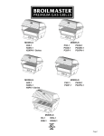
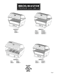
MODELS
H3X-2
H3PK1N-3
H3XN-2
H3PK2N-2
H3PK1-3
H3PK3N-2
MODELS
P3X-2
P3XN-2
P3SX-2
P3SXN-2
P3XF-2
P3XFN-2
MODELS
H4X-2
H4XN-2
H4PK-2 Series
MODELS
P4X-2
P4XN-2
P4XF-2
P4XFN-2
MODELS
R3-1
R3N-1
R3B-1
R3BN-1
GAS-FIRED
Page 1
IMPORTANT
This manual should be read thoroughly by the person installing the grill and all persons
who will use and maintain the grill. The installer should be sure the manual is left in the
possession of the user. The user should retain this manual for future reference when using or cleaning the grill and to properly identify any repair parts that may be required.
WARNING
Reference this manual for proper installation and maintenance instructions. Improper
installation, adjustment, alteration, service or maintenance can cause personal injury or
property damage. For assistance or additional information consult a qualified installer,
service agency or the gas supplier.
DANGER: FOR YOUR SAFETY
IF YOU SMELL GAS:
1.Shut off gas to the appliance.
2. Extinguish any open flame.
3. Open the grill lid.
4. If odor continues, keep away from the appliance and immediately call your gas supplier or your fire department.
WARNING: FOR YOUR SAFETY
1. Do not store or use gasoline or other flammable vapors or liquids in the vicinity of
this or any other appliance.
2. An LP cylinder not connected for use shall not be stored in the vicinity of this or any
other appliance.
CAUTION:
Parts may have sharp edges. Wear leather work gloves and handle parts carefully during the unpacking, assembly and installation.
WARNING
Broilmaster® Gas Grills must ONLY use propane cylinders equipped with an Overfill
Protection Device (OPD). Use only a reputable propane dealer when exchanging or
filling cylinders. An overfilled or improperly filled propane cylinder can be dangerous.
Page 2
B102163-0-1113
Congratulations!
Welcome to the beauty, durability, and prestige of a Premium Gas Grill
by Broilmaster®. With award-winning excellence built into every feature
and durability that surpasses other Premium gas grills, Broilmaster has
manufactured the ultimate gas grill for discriminating outdoor chefs for
over 30 years.
At Broilmaster, we continually strive to enhance the performance and
quality of our products for your grilling enjoyment. Every effort will be
made to ensure that Broilmaster continues to be your choice as the
Premium grill of the future.
Whether you are at the lake or in the privacy of your own backyard, the
Broilmaster® Premium Gas Grill performs far beyond the ordinary and is
designed to provide your family with years of outdoor cooking pleasure.
Thank You!
Broilmaster® is a registered trademark of
Empire Comfort Systems, Inc.
918 Freeburg Ave.
Belleville, Illinois 62220
Telephone 800-851-3153
B102163-0-1113
Page 3
Table of Contents
Congratulations!
You have chosen the finest grill for your outdoor cooking pleasure. Please take time to read this entire
manual before assembling your Premium Broilmaster® gas grill.
MASTER PARTS DISTRIBUTOR LIST.......................................................................................... 5
HOW TO ORDER REPAIR PARTS................................................................................................. 5
P3X SERIES PARTS DIAGRAM.................................................................................................... 6
P3X SERIES PARTS LIST.............................................................................................................. 7
P4X SERIES PARTS DIAGRAM.................................................................................................... 8
P4X SERIES PARTS LIST.............................................................................................................. 9
H3X SERIES PARTS DIAGRAM.................................................................................................. 10
H3X SERIES PARTS LIST............................................................................................................ 11
H4X SERIES PARTS DIAGRAM.................................................................................................. 12
H4X SERIES PARTS LIST............................................................................................................ 13
R3 SERIES PARTS DIAGRAM..................................................................................................... 14
R3 SERIES PARTS LIST.............................................................................................................. 15
GRILL ASSEMBLY....................................................................................................................... 16
WARRANTY TERMS...............................................................................................................16-17
PROPANE GAS GRILLS.........................................................................................................18-20
NATURAL GAS GRILLS.............................................................................................................. 21
OWNER’S MANUAL FOR P AND H SERIES GRILLS...........................................................22-32
HARDWARE PACK - H3, H4..................................................................................................... 23
HARDWARE PACK - P3, P4..................................................................................................... 24
GRILL ASSEMBLY...............................................................................................................25-29
OPERATION - PROPANE & NATURAL GAS GRILLS.............................................................. 30
OPERATION.............................................................................................................................. 30
MAINTENANCE........................................................................................................................ 31
TROUBLESHOOTING.............................................................................................................. 32
OWNER’S MANUAL FOR R SERIES GRILLS.......................................................................33-47
HARDWARE PACK................................................................................................................... 34
SAFETY PRECAUTIONS.......................................................................................................... 35
GRILL ASSEMBLY...............................................................................................................36-39
GAS CONVERSION TO NATURAL GAS.................................................................................. 40
INFRARED COOKING.............................................................................................................. 41
INFRARED COOKING SAMPLE TIMES................................................................................... 42
OPERATION - PROPANE & NATURAL GAS GRILLS.........................................................43-44
BLUE FLAME BURNER MAINTENANCE................................................................................. 45
INFRARED BURNER MAINTENANCE..................................................................................... 46
TROUBLESHOOTING.............................................................................................................. 47
Page 4
B102163-0-1113
MASTER PARTS DISTRIBUTOR LIST
To Order Parts Under Warranty, please contact your local Empire dealer. See the dealer locator at www.empirecomfort.com.
To provide warranty service, your dealer will need your name and address, purchase date and serial number, (located on
control panel heat shield) and the nature of the problem with the unit.
To Order Parts After the Warranty Period, please contact your dealer or one of the Master Parts Distributors listed below.
This list changes from time to time. For the current list, please click on the Master Parts button at www.empirecomfort.com.
Please note: Master Parts Distributors are independent businesses that stock the most commonly ordered Original Equipment repair parts for Heaters, Grills, and Fireplaces manufactured by Empire Comfort Systems Inc.
Dey Distributing
1401 Willow Lake Boulevard
Vadnais Heights, MN 55101
Victor Division of F. W. Webb Company
200 Locust Street
Hartford, CT 06114
Phone: 651-490-9191
Toll Free: 800-397-1339
Website: www.deydistributing.com
Parts: Heater, Hearth and Grills
Phone: 860-722-2433
Toll Free: 800-243-9360
Fax: 860-293-0479
Toll Free Fax: 800-274-2004
Websites: www.fwwebb.com & www.victormfg.com
Parts: Heater, Hearth and Grills
East Coast Energy Products
10 East Route 36
West Long Branch, NJ 07764
Able Distributors
2501 North Central Avenue
Chicago, IL 60639
Phone: 732-870-8809
Toll Free: 800-755-8809
Fax: 732-870-8811
Website: www.eastcoastenergy.com
Parts: Heater, Hearth and Grills
Phone: 773-889-5555
Toll Free: 800-880-2253
Fax: 773-466-1118
Website: www. abledistributors.com
Parts: Heater
HOW TO ORDER REPAIR PARTS
Parts Not Under Warranty
Parts can be ordered through your Service Person, Dealer, or a Master Parts Distributor. See this page for the Master Parts Distributors list. For best results, the service person or dealer should order parts through the distributor. Parts can be shipped directly to the
service person/dealer.
Warranty Parts
Warranty parts will need a proof of purchase and can be ordered by your Service Person or Dealer. Proof of purchase is required for
warranty parts.
All parts listed in the Parts List have a Part Number. When ordering parts, first obtain the Model Number and Serial Number from the
name plate on your equipment. Then determine the Part Number (not the Index Number) and the Description of each part from the following illustration and part list. Be sure to give all this information . . .
Appliance Model Number
Appliance Serial Number
Part Description
Part Number
Type of Gas (Propane or Natural)
Do not order bolts, screws, washers or nuts. They are standard hardware items and can be purchased at any local hardware store.
Shipments contingent upon strikes, fires and all causes beyond our control.
B102163-0-1113
Page 5
P3X SERIES PARTS DIAGRAM
All repair part orders should be placed through your local Broilmaster® dealer. To locate a dealer in your
area visit www.broilmaster.com. To ensure prompt and accurate service, please provide the following
information when placing a repair part order: Model Number, Serial Number, Part Name, Part Number,
and Quantity of parts needed.
Page 6
B102163-0-1113
P3x SERIES PARTS LIST
Index
No.
Description
Part Number
P3SX
P3SXN
P3X
P3XN
P3XF
P3XFN
1
Grill Body Top (with heat indicator, hinge)
B102042
B102042
B102042
B102042
B102042
B102042
1
Grill Body Top (casting only)
B101883
B101883
B101883
B101883
B101883
B101883
2
Heat Indicator (stainless) with push nut
DPP119
DPP119
DPP119
DPP119
DPP119
DPP119
3
Lid Handle (stainless)
B070486
B070486
B070486
B070486
B070486
B070486
4
Foam Grip
B073097
B073097
B073097
B073097
B073097
B073097
5
Retract-A-Rack (stainless)
B072695
B072695
B072695
B072695
B072695
B072695
6
Cooking Grid (two piece Stainless Steel
DPA111
DPA111
DPA111
DPA111
DPA111
DPA111
7
Briquette Bag
N/A
N/A
DPA34
DPA34
N/A
N/A
8
Briquette Rack
B101061
B101061
B101061
B101061
B101061
B101061
9
Burner Assembly
DPP111
DPP111
DPP111
DPP111
DPP111
DPP111
10
Wind Deflector
B101742
B101742
B101742
B101742
B101742
B101742
11
Bridge Pin
B057805
B057805
B057805
B057805
B057805
B057805
12
Hinge Pin
B057804
B057804
B057804
B057804
B057804
B057804
13
Lid Stop Kit
DPA106
DPA106
DPA106
DPA106
DPA106
DPA106
14
Orifice - LPG (#54 drill)
P204
P204
P204
P204
P204
P204
15
Orifice - NAT (#48 drill)
P300
P300
P300
P300
P300
P300
16
Electric Ignitor
B072218
B072218
B072218
B072218
B072218
B072218
17*
Valve - LPG (without orifices)
B101420
B101420
B101420
B101420
B101420
B101420
18*
Valve - NAT (without orifices)
B101421
B101421
B101421
B101421
B101421
B101421
19
Shelf Pin
B073963
B073963
B073963
B073963
B073963
B073963
20
Control Panel Assembly (with label and shield)
B102167
B102167
B102167
B102167
B102167
B102167
20
Control Panel Label (not shown)
B101517
B101517
B101517
B101517
B101517
B101517
21
Valve Knob - Black
B070084
B070084
B070084
B070084
B070084
B070084
22
Grill Body Bottom (casting only)
B101879
B101879
B101879
B101879
B101879
B101879
23
Control Panel Shield
B101622
B101622
B101622
B101622
B101622
B101622
24
Electrode Bracket
B101834
B101834
B101834
B101834
B101834
B101834
25
Electrode
B101666
B101666
B101666
B101666
B101666
B101666
26
Protective Sleeve
B102041
B102041
B102041
B102041
B102041
B102041
27
Flare Busters Kit
DPA116
DPA116
N/A
N/A
DPA116
DPA116
28
Burner Bracket
DPP118
DPP118
DPP118
DPP118
DPP118
DPP118
29
Push Nut
B101665
B101665
B101665
B101665
B101665
B101665
30
Hose & LPS Regulator
B069756
N/A
B069756
N/A
B069756
N/A
31
Griddle, Stainless Steel
B101400
B101400
N/A
N/A
N/A
N/A
32
Smoker/Shutter (includes Actuator Arm & Knob
DPA100
DPA100
N/A
N/A
N/A
N/A
33
Collector Box Assembly
DPP116
DPP116
DPP116
DPP116
DPP116
DPP116
NS
Ignitor Ground Wire
B072684
B072684
B072684
B072684
B072684
B072684
NS
Hardware Package
B101973
B101973
B101973
B101973
B101973
B101973
NS
Actuator Arm - Smoker/Shutter
B100408
B100408
N/A
N/A
N/A
N/A
NS
Knob - Smoker/Shutter Knob
B100098
B100098
N/A
N/A
N/A
N/A
NS - Not Shown
*Valves are not convertible. To convert the unit to a different gas type, a new valve must be purchased.
B102163-0-1113
Page 7
P4X SERIES PARTS DIAGRAM
All repair part orders should be placed through your local Broilmaster® dealer. To locate a dealer in your
area visit www.broilmaster.com. To ensure prompt and accurate service, please provide the following
information when placing a repair part order: Model Number, Serial Number, Part Name, Part Number,
and Quantity of parts needed.
29
2
30
1
3
4
5
27
6
7
8
31
9
28
17 or 18
34
24
10
25
14 or 15
11
26
12
21
16
22
19
20
23
Page 8
B102163-0-1113
P4X SERIES PARTS LIST
Index
No.
Description
Part Number
P4X
P4XN
P4XF
P4XFN
1
Grill Body Top (with heat indicator, hinge)
B102043
B102043
B102043
B102043
1
Grill Body Top (casting only)
B076621
B076621
B076621
B076621
2
Heat Indicator (stainless)
DPP119
DPP119
DPP119
DPP119
3
Lid Handle (stainless)
B070486
B070486
B070486
B070486
4
Foam Grip
B073097
B073097
B073097
B073097
5
Warming Rack (stainless)
B072696
B072696
B072696
B072696
6
Cooking Grid (two piece Stainless Steel
DPA112
DPA112
DPA112
DPA112
7
Briquette Bag
DPA34
DPA34
N/A
N/A
8
Briquette Rack
B067449
B067449
B067449
B067449
9
Burner Assembly
DPP111
DPP111
DPP111
DPP111
10
Wind Deflector
B101742
B101742
B101742
B101742
11
Bridge Pin
B057805
B057805
B057805
B057805
12
Hinge Pin
B057804
B057804
B057804
B057804
13
Lid Stop Kit
DPA106
DPA106
DPA106
DPA106
14
Orifice - LPG (#55 drill)
P182
P182
P182
P182
15
Orifice - NAT (#49 drill)
P265
P265
P265
P265
16
Electric Ignitor
B072218
B072218
B072218
B072218
17*
Valve - LPG (without orifices)
B101420
B101420
B101420
B101420
18*
Valve - NAT (without orifices)
B101421
B101421
B101421
B101421
19
Shelf Pin
B073963
B073963
B073963
B073963
20
Control Panel Assembly (w/label and shield)
B102168
B102168
B102168
B102168
20
Control Panel Label
B101518
B101518
B101518
B101518
21
Valve Knob - Black
B070084
B070084
B070084
B070084
22
Grill Body Bottom (casting only)
B101443
B101443
B101443
B101443
23
Control Panel Shield
B101621
B101621
B101621
B101621
24
Electrode Bracket
B101834
B101834
B101834
B101834
25
Electrode
B101666
B101666
B101666
B101666
26
Protective Sleeve
B102041
B102041
B102041
B102041
27
Flare Busters Kit
N/A
N/A
DPA117
DPA117
28
Burner Bracket
DPP118
DPP118
DPP118
DPP118
29
Push Nut
B101665
B101665
B101665
B101665
30
Mounting Plate Assembly
B101997
N/A
B101997
N/A
31
Hose & LPS Regulator
B069756
N/A
B069756
N/A
34
Collector Box Assembly
DPP116
DPP116
DPP116
DPP116
NS
Hardware Package - LPG & NAT
B101973
B101973
B101973
B101973
NS
Ignitor Ground Wire
B072684
B072684
B072684
B072684
NS - Not Shown
*Valves are not convertible. To convert the unit to a different gas type, a new valve must be purchased.
B102163-0-1113
Page 9
H3X SERIES PARTS DIAGRAM
All repair part orders should be placed through your local Broilmaster® dealer. To locate a dealer in your
area visit www.broilmaster.com. To ensure prompt and accurate service, please provide the following
information when placing a repair part order: Model Number, Serial Number, Part Name, Part Number,
and Quantity of parts needed.
2
30
29
31
24
25
26
27
Page 10
B102163-0-1113
H3X SERIES PARTS LIST
Index No.
Part Description
Part Number
H3X
H3XN
1
Grill Body Top (with heat indicator, hinge,
B102042
B102042
1
Grill Body Top (casting only)
B100456
B100456
2
Heat Indicator (stainless)
DPP119
DPP119
3
Lid Handle (stainless)
B070486
B070486
4
Foam Grip
B073097
B073097
5
Warming Rack (Chrome)
B100594
B100594
6
Cooking Grid (two piece Stainless Steel)
B101397
B101397
7
Briquette Bag
B058122
B058122
8
Briquette Rack
B101061
B101061
9
Burner Assembly
DPP109
DPP109
10
Wind Deflector
B063065
B063065
11
Bridge Pin
B057805
B057805
12
Hinge Pin
B057804
B057804
Lid Stop Kit
13**
DPA106
DPA106
14
Orifice - LPG (#55 drill)
P182
P182
15
Orifice - NAT (#49 drill)
P265
P265
16
Electric Ignitor
B072218
B072218
17*
Valve - LPG (without orifices)
B101420
B101420
18*
Valve - NAT (without orifices)
B101421
B101421
19
Shelf Pin
B073963
B073963
20
Control Panel Assembly (with label)
B101563
B101563
20
Control Panel Label (not shown)
B101517
B101517
21
Valve Knob - Black
B070084
B070084
22
Grill Body Bottom (casting only)
B101879
B101879
23
Control Panel Shield
B101622
B101622
24
Electrode Bracket
B101834
B101834
25
Electrode
B101666
B101666
26
Protective Sleeve
B102041
B102041
27
Burner Bracket
DPP118
DPP118
28
Hose & LPS Regulator
B069756
N/A
29
Push Nut
B101665
B101665
30
Mounting Plate Assembly
B101997
B101997
31
Collector Box Assembly
DPP116
DPP116
NS
Hardware Package
B101971
B101971
NS
Ignitor Ground Wire
B072684
B072684
NS - Not Shown
*Valves are not convertible. To convert the unit to a different gas type, a new valve must be purchased.
**Note: H3 Series grills do not come with a Lid Stop Kit. The Lid Stop Kit must be purchased separately.
B102163-0-1113
Page 11
H4X SERIES PARTS DIAGRAM
2
29
30
1
3
4
5
6
7
8
31
28
9
17 or 18
24
25
10
26
14 or 15
11
27
12
21
16
22
19
20
23
Page 12
B102163-0-1113
H4X SERIES PARTS LIST
Index No.
Description
Part Number
H4X
H4XN
1
Grill Body Top (with heat indicator, hinge)
B102043
B102043
1
Grill Body Top (casting only)
B076621
B076621
2
Heat Indicator (stainless)
DPP119
DPP119
3
Lid Handle (stainless)
B070486
B070486
4
Foam Grip
B073097
B073097
5
Warming Rack (stainless)
B072696
B072696
6
Cooking Grid
DPA114
DPA114
7
Briquette Bag
DPA34
DPA34
8
Briquette Rack
B067449
B067449
9
Burner Assembly
DPP115
DPP115
10
Wind Deflector
B101742
B101742
11
Bridge Pin
B057805
B057805
12
Hinge Pin
B057804
B057804
Lid Stop Kit
DPA106
DPA106
P312
P312
13**
14
Orifice - LPG (#122 mm)
15
Orifice - NAT (#50 drill)
P245
P245
16
Electric Ignitor
B072218
B072218
17*
Valve - LPG (without orifices)
B101420
B101420
18*
Valve - NAT (without orifices)
B101421
B101421
19
Shelf Pin
B073963
B073963
20
Control Panel Assembly (w/label and shield)
B102168
B102168
20
Control Panel Label
B101518
B101518
21
Valve Knob - Black
B070084
B070084
22
Grill Body Bottom (casting only)
B101443
B101443
23
Control Panel Shield
B101621
B101621
24
Collector Box Assembly
DPP116
DPP116
25
Electrode Bracket
B101834
B101834
26
Electrode
B101666
B101666
27
Protective Sleeve
B102041
B102041
28
Burner Bracket
DPP118
DPP118
29
Push Nut
B101665
B101665
30
Mounting Plate Assembly
B101997
B101997
31
Hose & LPS Regulator
B069756
N/A
NS
Hardware Package - LPG & NAT
DPP116
DPP116
NS
Ignitor Ground Wire
B072684
B072684
NS - Not Shown
*Valves are not convertible. To convert the unit to a different gas type, a new valve must be purchased.
**Note: H4 Series grills do not come with a Lid Stop Kit. The Lid Stop Kit must be purchased separately.
B102163-0-1113
Page 13
R3 SERIES PARTS DIAGRAM
All repair part orders should be placed through your local Broilmaster dealer. To locate a dealer in your
area, visit www.Broilmaster.com. To ensure prompt and accurate service, please provide the following
information when placing a repair part order: Model Number, Serial Number, Part Name, Part Number,
and Quantity of parts needed.
1
2
3
5
4
6
7
24
9
15
25
8
26
12
13
10
11
14
16
19
20
21
22
18
23
17
Page 14
B102163-0-1113
R3 SERIES PARTS LIST
Index
No.
Description
Part Number
R3
R3N
R3B
R3BN
1
Grill Body Top - Black
B100456
B100456
B100456
B100456
2
Heat Indicator (Stainless)
B101406
B101406
B101406
B101406
3
Lid Handle (Stainless)
B070486
B070486
B070486
B070486
4
Foam Grip
B073097
B073097
B073097
B073097
5
Stainless Steel Retract-A-Rack
B072695
B072695
B072695
B072695
6
Stainless Steel V-Channel Cooking Grid
(Qty 2 for R3 and R3N)
DPA121
DPA121
DPA121
DPA121
7
Briquet Rack
N/A
N/A
B101369
B101369
8
Burner
N/A
N/A
B101030
B101030
9
Burner Shield
N/A
N/A
B101154
B101154
10
Collector Box Assembly
N/A
N/A
B101212
B101212
11
Ignitor Spacer
N/A
N/A
B101082
B101082
12
Infrared Burner (one required)
N/A
N/A
B102180
B102180
12
Infrared Burner (two required)
B102180
B102180
N/A
N/A
13
Wind Deflector
B101045
B101045
B101045
B101045
14
Grill Body Bottom - Black
B101881
B101881
B101881
B101881
15
Infrared Ignitor (one Required)
N/A
N/A
B101271
B101271
15
Infrared Ignitor (two Required)
B101271
B101271
N/A
N/A
16
Control Panel Shield
B101046
B101046
B101046
B101046
17
Pin, Shelf
B073963
B073963
B073963
B073963
18
Manifold And Valve Assembly (includes orifices)
B101356
B101316
B101314
B101317
19
Electronic Ignitor
B072218
B072218
B072218
B072218
20
Control Panel Assembly (w/label and shield)
B102169
B102169
B102169
B102169
21
Control Panel Label
B101272
B101272
B101272
B101272
22
Valve Knob
R3918
R3918
R3918
R3918
23
Hose And LP Regulator
B069756
N/A
B069756
N/A
24*
Control Housing - Stainless Steel
B101121
B101121
B101121
B101121
25**
Cover Plate - Black
B101596
B101596
B101596
B101596
25a**
Cover Plate - Black
B101767
B101767
B101767
B101767
25**
Cover Plate - Stainless Steel
B101597
B101597
B101597
B101597
25b**
Cover Plate - Stainless Steel
B101768
B101768
B101768
B101768
B102182
B102182
B102182
B102182
N/A
N/A
B101323
B101323
B101274
B101275
B101309
B101310
26
Burner Screen
N/S
Char-Master Briquets
N/S
Hardware Pack
N/S
Bridge Pin
B057805
B057805
B057805
B057805
N/S
Hinge Pin
B057804
B057804
B057804
B057804
N/S
Natural Gas Conversion Kit
BCK1004
N/A
BCK1004
N/A
N/S
Ground Lug (two Required)
B069747
B069747
N/A
N/A
N/S
Ground Wire
B072684
B072684
N/A
N/A
N/S
Hardware Pack, Adjustable Lid Stop
B101097
B101097
B101097
B101097
N/S - NOT SHOWN
*Control Housing is used only when installing grill head onto cart. See the instructions that come with the cart for Control Housing
installation instructions.
** Cover Plate is used only when installing grill head onto post. See the instructions that come with the post for Cover Plate installation
instructions.
B102163-0-1113
Page 15
GRILL ASSEMBLY
Before You Begin
Recommended Tools
All Broilmaster grills require some assembly and installation. Follow
all instructions unless noted to apply only to other specific models.
These items are recommended for the assembly of your grill:
Do NOT use power tools.
If you purchased an accessory with your Broilmaster, follow
the instructions provided with the accessory for assembly and
installation. If an instruction refers to a step that is not required for
your grill model, please continue to the next step.
•
•
•
•
•
Compare the parts found in the shipping container to the parts list
provided. If any parts are missing contact your Broilmaster® dealer
before beginning assembly.
CAUTION: FOR YOUR SAFETY
Parts may have sharp edges. Wear leather work gloves and
handle parts carefully during the unpacking, assembly and
installation.
Phillips screwdriver
Adjustable wrench set
Socket set
Soapy water solution (to test for leaks)
Liquid soap (for foam grip)
Grill Mountings
Assemble your base option before assembling your Broilmaster® grill head.
Refer to the Broilmaster® Cart, Base, and Post instructions
provided with each accessory for assembly, installation, and
mounting procedures.
WARRANTY TERMS
Empire Comfort Systems Inc. warranties this Broilmaster premium gas grill to be free from defects at the time of purchase and for the
periods specified below. Broilmaster Premium Gas Grills must be installed by a qualified technician and must be maintained and operated safely, in accordance with the instructions in the owner’s manual. This warranty applies to the original purchaser only and is not
transferable. All warranty repairs must be accomplished by a qualified gas appliance technician.
Limited Lifetime Parts Warranty – Against Rust-Through
If the items listed below fail because of defective workmanship or material, Empire will repair or replace at Empire’s option.
• Aluminum Grill Housing (except paint)
• Stainless Steel Cooking Grids and Stainless Steel Griddles
• Select Stainless Steel Components – Cart, Mounting, Bowtie Burner, Side Burner (DPA150, DPA151), Side Burner Housing
(DPA152), and Warming Rack
• Stainless Steel Built-In Components – Built-In Kits for 3-Series Grill Heads, Door Kit, Tilt-Out LP Tank Door, and Vent Register
Kit
Limited Ten-Year Parts Warranty – Against Rust-Through
If the items listed below fail because of defective workmanship or material, Empire will repair or replace at Empire’s option.
• H-Series and R3B Stainless Steel Burners
Page 16
B102163-0-1113
WARRANTY TERMS
Limited Five-Year Parts Warranty – Against Rust-Through
If the items listed below fail because of defective workmanship or material, Empire will repair or replace at Empire’s option.
• Infrared Burners on R3 or R3B
• Flare Buster™ Ceramic Flavor Enhancers
• Painted Electro-Galvanized Steel Components
• Stainless Steel Smoker Shutter
Limited Two-Year Parts Warranty – Against Rust-Through
If the items listed below fail because of defective workmanship or material, Empire will repair or replace at Empire’s option.
• Porcelain Coated Steel Briquette Racks
• Chrome-Plated Warming Rack
• Stainless Steel Flavor Screen
• Stainless Steel Heat Shield
Limited One-Year Parts Warranty
If the items listed below fail because of defective workmanship or material, Empire will repair or replace at Empire’s option.
• Valves, knobs, ignitors, labels, hoses, fittings and all other parts and accessories – including those made from stainless steel –
unless specified above
• Paint on Aluminum Grill Head
Duties Of The Owner
The appliance must be installed by a qualified installer and operated in accordance with the instructions furnished with the appliance.
A bill of sale, cancelled check, or payment record should be kept to verify purchase date and establish warranty period.
Ready access to the appliance for service.
What Is Not Covered
Damages that might result from the use, misuse, or improper installation or storage of this appliance.
Travel, diagnostic costs and freight charges on warranted parts to and from the factory.
Claims that do not involve defective workmanship or materials.
Unauthorized service or parts replacements.
Removal and reinstallation cost.
Inoperable due to improper or lack of maintenance.
The costs of a service call to diagnose a problem and labor for replacement or repairs.
How To Get Service
To make a claim under this warranty, please have your receipt available and contact your installing dealer. Provide the dealer
with the model number, serial number, type of gas, and purchase verification. The installing dealer is responsible for providing service
and will contact the factory to initiate any warranted parts replacements. Empire will make replacement parts available at the factory.
Shipping expenses are not covered.
If, after contacting your Empire dealer, service received has not been satisfactory, contact: Consumer Relations Department,
Empire Comfort Systems Inc., PO Box 529, Belleville, Illinois 62222, or send an e-mail to [email protected] with “Consumer
Relations” in the subject line.
Your Rights Under State Law
This warranty gives your specific legal rights, and you may also have other rights, which vary from state to state.
Broilmaster is a Division of Empire Comfort Systems, Inc.
B102163-0-1113
Page 17
PROPANE GAS GRILLS
Grill Location
When choosing the ideal location for your Broilmaster® Premium
Gas Grill, remember this grill is designed for outdoor use ONLY.
Cylinder Requirements
Your Broilmaster® Premium Gas Grill requires a standard twenty
pound propane gas cylinder.
You should never install or operate your grill in any building, garage,
or other enclosed area.
The maximum height allowable for a replacement cylinder is approximately twelve inches (30.5 centimeters).
For your safety, this grill should not be installed or operated under
any combustible materials, such as carports, covered porches,
awnings, or overhangs.
The propane gas cylinder used must be:
Never install or operate your grill in or on any recreational vehicle
or boat.
CAUTION: The installation and operation of this grill at clearances less than specified below may lead to the possibility of
fire, property damage, or personal injury.
A minimum clearance of 16 inches is required from the sides of the
grill to any combustible material.
A minimum clearance of 18 inches is required from the back of the
grill to any combustible material.
Some examples of combustible materials are a wall, a fence, patio
furniture, or the wall of your home.
The area surrounding the grill should be clear to ensure proper
ventilation. Do not obstruct the flow of combustion and ventilation
air in any way. The ventilation openings on the propane cylinder
enclosure must also remain free and clear of debris.
Portable grills should be level and positioned away from direct wind
prior to each use.
1. Constructed and marked in accordance with the specifications
for LP gas cylinder of the U.S. Department of Transportation
(D.O.T.) or the National Standard of Canada, CAN/CSA-B339,
Cylinders, Spheres, and Tubes for Transportation of Dangerous
Goods; and Commission as applicable.
2. Provided with a listed overfilling protection device (OPD).
3. Provided with a listed safety device having direct access with
the vapor space of the cylinder and the cylinder supply system
must be arranged for vapor removal.
4. Provided with a shutoff valve terminating in a valve outlet as
specified in the Standard for Compressed Gas Cylinder Outlet
and Inlet Connections, ANSICGA-V-1.
5. Provided with a plug to effectively seal off the cylinder outlet
when the cylinder is being stored or transported.
6. Provided with a collar to protect the cylinder valve.
Caution: Do not use a propane gas cylinder which has a capacity greater than twenty pounds with this grill and side burner.
WARNING: Do not install or operate this grill where gasoline or other flammable materials are used or stored. Failure
to comply with this warning could result in explosion or fire
causing property damage or personal injury.
Page 18
B102163-0-1113
PROPANE GAS GRILLS
Propane Cylinder Safety
Liquid Propane (LP) gas has a long history of safe use when the
safety precautions provided in this manual are followed.
Failure to follow these safety precautions could result in a
fire or explosion causing property damage or personal injury.
Propane gas cylinders should always be handled, stored, and
transported with extreme caution in a secured upright position.
Never attempt to use or repair a propane gas cylinder that has been
damaged. Never attempt to use or repair a cylinder with a faulty or
damaged valve outlet. A cylinder that has been dropped, dented,
or otherwise damaged must be replaced.
A propane gas cylinder should never be transported in the passenger area of a vehicle.
Keep cylinders out of direct sunlight and never apply any other
source of direct heat to them.
When refilling your cylinder, always insist on a reputable, qualified
gas dealer. Your propane gas cylinder is filled by weight, and should
never exceed eighty percent (80%) of its weight limit. If the cylinder is not completely empty, the gas dealer must make necessary
adjustments to ensure it is not overfilled. Never use an overfilled
Propane gas cylinder.
Cylinder Storage
Your grill must be stored outdoors in a well ventilated area if the
cylinder is attached to it.
Connection Requirements
Caution: Never use Liquid Propane (LP) gas in a grill designed
for Natural gas, or Natural gas in a grill designed for Liquid
Propane gas. Questions regarding different types of gases
should be directed to your local gas supplier.
Installation must conform to local codes or, in the absence of local
codes, with the National Fuel Gas Code, ANSI Z223.1. In Canada,
installation shall be in accordance with CAN/CGA-B149.2 Propane
Installation Code, or CAN/CGA-B149.1 Natural Gas Installation
Code, and local codes where applicable. Consult your local gas
supplier or propane gas dealer for code regulations and recommended procedures.
Warning: Broilmaster® Premium Gas Grills require Liquid
Propane (LP) cylinders equipped with an Overfill Protection
Device (OPD). An overfilled or improperly filled Propane cylinder can be dangerous.
Always use the pressure regulator and hose assembly supplied
with your Propane gas grill.
Note: Not all valve and cylinder combinations are compatible.
Check warning tag on valve and cylinder as well as external fitting
threads.
All Broilmaster® pressure regulators and hose assemblies require
Propane cylinders with a Type 1 connection device as illustrated.
See Figure 1.
Disconnected cylinders must have a threaded valve plug tightly
installed and must not be stored in any building, garage, or other
enclosed area.
Flammable materials (gasoline, grill covers, etc.) must not be stored
in the cylinder enclosure.
Always store Propane cylinders in a secured upright position, out
of the reach of children.
Figure 1
B102163-0-1113
Page 19
PROPANE GAS GRILLS
Pressure Regulator and Hose Assembly
The pressure regulator has an outlet pressure of not more than
eleven inches water column. It must be connected to the Propane
gas cylinder’s female valve outlet before the grill can be operated.
Caution: Operation of a Propane gas grill without the pressure regulator and hose assembly will cause gas leaks which
could lead to fire or explosion, resulting in property damage
or personal injury.
Connecting to Propane Gas / Cylinder Retention Means
ATTENTION:
Propane gas cylinders that are acceptable for
use with this grill must comply with Cylinder Requirements, Page
18, and Connection Requirements, Page 19.
Position the cylinder in the opening in the bottom of the cart and
secure with the cylinder retaining bracket. See Figure 2.
The pressure regulator’s fitting must remain clean and free of nicks
and scratches. A dirty, nicked or scratched fitting can cause a gas
leak, resulting in an explosion or fire. Use only genuine Broilmaster®
replacement parts unless otherwise specified by the manufacturer.
Figure 2
Attach the pressure regulator to the Propane gas cylinder’s valve
using the plastic handwheel. Tighten in a clockwise motion to
achieve a gas tight seal. See Figure 3.
CLOCKWISE
Figure 3
Caution: Do not use a wrench or any other tool to tighten. Use
of a wrench or other tool will damage the plastic handwheel.
To disconnect the Propane gas cylinder, turn OFF the cylinder’s
valve and the grill’s control valve. Remove the regulator by turning
the plastic handwheel counterclockwise.
Caution: Assure hose does not touch the casting or mounting
components.
Page 20
B102163-0-1113
NATURAL GAS GRILLS
Grill Location
When choosing the ideal location for your Broilmaster Premium
Gas Grill, remember this grill is designed for outdoor use ONLY.
You should never install or operate your grill in any building, garage,
or other enclosed area.
For your safety, this grill should not be installed or operated under
any combustible materials, such as carports, covered porches,
awnings, or overhangs.
Never install or operate your grill in or on any recreational vehicle
or boat.
CAUTION: The installation and operation of this grill at clearances less than specified below may lead to the possibility of
fire, property damage, or personal injury.
A minimum clearance of 16 inches is required from the sides of the
grill to any combustible material.
A minimum clearance of 18 inches is required from the back of the
grill to any combustible material.
Some examples of combustible materials are a wall, a fence, patio
furniture, or the wall of your home.
The area surrounding the grill should be clear to ensure proper
ventilation. Do not obstruct the flow of combustion and ventilation
air in any way. The ventilation openings on the propane cylinder
enclosure must also remain free and clear of debris.
Portable grills should be level and positioned away from direct wind
prior to each use.
WARNING: Do not install or operate this grill where gasoline or other flammable materials are used or stored. Failure
to comply with this warning could result in explosion or fire
causing property damage or personal injury.
Gas Type
The type gas required for your grill can be determined from the
product identification label located on the grill’s control panel.
Questions regarding different types of gases should be directed to
your local gas supplier.
Connection Requirements
Broilmaster grills are not equipped with pressure regulators. Your
gas grill operates at a manifold pressure of seven inches water
column.
Connect cart mounted Natural gas grills to a pre-installed gas
supply line using the twelve foot flexible hose and quick disconnect
kit which can be purchased from your local dealer.
Hazardous Locations and Conditions
• The LP gas cylinder must be arranged upright for vapor withdrawal.
• Do not obstruct the flow of combustion and ventilation air.
• This grill should only be used outdoors in a well-ventilated space
must not be used in a building, garage, or any other enclosed
area.
• Keep all flammable substances away from the grill. These
include most aerosols and aerosol containers, gasoline and
similar liquids, paper and paper products, containers of grease,
paint, etc.
• Never store flammable materials or objects such as those
described above in the pedestal base.
• Never leave grill unattended while in operation.
• Never use any liquid in an attempt to control flare-up.
• It may be necessary to adjust your grill away from the direction
of prevailing wind.
• Avoid wearing flammable and/or loose clothing such as longsleeves, neckties, scarves, aprons, etc., while the grill is in
operation.
• Avoid contact of hair to heat and flames.
Caution: The grill and its individual shutoff valve must be
disconnected from the gas supply piping system during any
system pressure testing at test pressures in excess of 1/2 PSIG.
Caution: The grill must be isolated from the gas supply piping
system by closing its individual manual shutoff valve during
any pressure testing of the gas supply piping system at test
pressures equal to or less than 1/2 PSIG.
Caution: Never use Liquid Propane (LP) gas in a grill designed
for Natural gas, or Natural gas in a grill designed for Liquid
Propane gas. Questions regarding different types of gases
should be directed to your local gas company.
B102163-0-1113
Page 21
Owner’s Manual For Models
P3X-2
P3SX-2
P3XF-2
P3XN-2
P3SXN-2
P3XF-2
P4X-2
P4XF-2
P4XN-2
P4XF-2
H3X-3
H3XN-3
H4X-2
H4XN-2
GAS-FIRED
Page 22
B102163-0-1113
HARDWARE PACK - h3, h4
BRIDGE PIN
10-24 KEPS NUT
PHILLIPS TRUSS HEAD SCREW 10-24 X 1
KNOB
AA BATTERY
DESCRIPTION
1/4-20 HEX NUT
PHILLIPS TRUSS HEAD SCREW 1/4-20 X 1 1/2
WIRE, IGNITOR GROUND
PART NUMBER
QUANTITY SUPPLIED
10-24 KEPS NUT
B073967
2
PHILLIPS TRUSS HEAD SCREW 10-24 X 1
B073978
2
1/4-20 HEX NUT
B076331
1
PHILLIPS TRUSS HEAD SCREW 1/4-20 X 1-1/2
B101649
1
BRIDGE PIN
B057805
1
KNOB, VALVE
B070084
2
WIRE, IGNITOR GROUND
B072084
1
GRIP, FOAM (NOT SHOWN)
B073097
1
BATTERY, AA
B076529
1
B102163-0-1113
Page 23
HARDWARE PACK - P3, P4
PHILLIPS TRUSS HEAD SCREW 10-24 X 1
1/4-20 HEX NUT
PHILLIPS TRUSS HEAD SCREW 1/4-20 X 1 1/2
BRIDGE PIN
1/4 ID X 5/8 OD FLAT WASHER
KNOB
AA BATTERY
LID STOP
DESCRIPTION
WIRE, IGNITOR GROUND
LID STOP KNOB
SPACER, LID STOP
PART NUMBER
QUANTITY SUPPLIED
10-24 KEPS NUT
B073967
2
PHILLIPS TRUSS HEAD SCREW 10-24 X 1
B073978
2
1/4-20 HEX NUT
B076331
1
1/4 ID X 5/8 OD FLAT WASHER
B076332
2
PHILLIPS TRUSS HEAD SCREW 10-24 X 3/4
B100128
1
R4021
1
PHILLIPS TRUSS HEAD SCREW 1/4-20 X 1 1/2
B101649
1
BRIDGE PIN
B057805
1
KNOB, VALVE
B070084
2
WIRE, IGNITER GROUND
B072684
1
GRIP, FOAM (NOT SHOWN)
B073087
1
BATTERY, AA
B076529
1
LID STOP
B076521
1
KNOB, TAPERED, LID STOP
B100098
1
SPACER, LID STOP
B662325
1
10-24 HEX NUT, LOCK
Page 24
10-24 HEX NUT, LOCK
PHILLIPS TRUSS HEAD SCREW 10-24 X 3/4
10-24 KEPS NUT
B102163-0-1113
GRILL ASSEMBLY
Installing the Hose and Regulator
To ease assembly, remove grill top before assembling. Remove the
2 pins and clips at the rear of the grill top and set aside. See Figure 4.
Installing Control Panel Shield
Attach shield by inserting the shield over the studs. See Figure 6.
Figure 6
Installing Control Panel
Attach control panel assembly to grill bottom with two 10-24 keps
nuts. See Figure 7.
Figure 4
LP Models: Attach the hose and regulator supplied with the unit as
shown in Figure 5.
Nat Gas Models: Attach the 12 foot quick connect hose (NG12 - not
supplied with unit).
For Post Installations: See post mounting instructions for assembly
and installation of gas-line hook-up.
Figure 7
Figure 5
B102163-0-1113
Page 25
GRILL ASSEMBLY
Burner Bracket Securing Bolt
1. Insert the 1/4-20 x 1 1/2 Phillips Truss Head Screw from the
underside of the grill and secure with the 1/4-20 Hex Nut. See
Figure 8.
Note:
Figure 8
If the Grill Head is installed on a PCB1, PSCB or DCB1,
make sure the cart shield is not installed until the burner
bracket securing bolt is installed.
Install Head to Mounting
1. Install Grill Head on a Cart or Post Mounting (see Cart or Post
Installation Instructions that come with the mounting option).
Heat Shield / Wind Shield
Place the heat and wind shield in the grill bottom. See Figure 9.
Ignitor Wire
Note: Install the Ignitor Ground Wire before installing the burner.
1. Connect the ground wire to the ground lug on the collector box
before installing the burner into the grill. See Figure 10.
Figure 10
Installing the Burner
1. The burner bracket should be at a slight angle as shown in
Figure 11. Once the proper angle is achieved, tighten the screw
securing the burner bracket to the venturi assembly and burner
body.
11°
CL
Figure 9
Note: The heat shield cannot be installed until after the grill is
installed on a post or cart.
Page 26
“H” SERIES
SHOWN
“H”
Series BURNER
Burner Shown
Figure 11
B102163-0-1113
GRILL ASSEMBLY
2. Insert the burner assembly into the grill bottom with the venturi
tubes facing the front of the grill. Slide venturis and ignitor wires
down through the center hole. See Figure 12.
Figure 12
3. Slide the venturi on to the valve assembly.
4. Raise the unsecured end of the burner bracket and slip it over
the 1/4-20 x 1 1/2 Phillips Truss Head Screw as shown in Figure
13. The screw will fit into the hole on the burner bracket.
Figure 14
“P” Series Shown
Figure 13
5. Slide the bridge pin through the hole in the 1/4-20 x 1 1/2 Phillips Truss Head Screw as shown in Figure 14.
B102163-0-1113
Page 27
GRILL ASSEMBLY
Connect Ignitor Wires and Install Battery
1. Attach ground and igniter wires to the igniter as shown in Figure
15.
2. Remove push button cap and insert AA battery, positive side
up as shown in Figure 15.
IGNITOR
CONNECTIONS
Lid Stop
Attach the lid stop assembly to the grill bottom as shown.
See Figure 18.
Note: H3X/H4X Series grills do not come with a Lid Stop Kit. The
Lid Stop Kit is available as an accessory.
Figure 18
Figure 15
Handle
For your added comfort a foam grip has been provided. See
Figure 16.
Installing Flare Busters
Place the briquet rack in the grill.
Position the flare busters as shown in Figures 19a and 19b.
Tip: For ease of installation, slightly lubricate the front handle with
liquid soap before pushing the foam grip into place.
Fasten the front handle to the grill lid with two #10-24 x 1" screws.
See Figure 17.
Figure 16
P3X - Figure 19a
Figure 17
Install Side Shelf
1. Install side shelves or side burner to side of grill at this time.
Reinstall Grill Head Top
1. Reinstall grill top to grill bottom with 2 pins and clips removed
in Figure 4.
P4X - Figure 19b
Installing Racks
Place the briquet rack or on the burner assembly.
Position the flare busters on the briquette rack or the ceramic
Page 28
B102163-0-1113
GRILL ASSEMBLY
briquets evenly on the briquette rack without overlapping. See
Figures 19a and 19b.
For Smoker Shutter installation see DPA100 manual included with
your P3SX grill.
Set the multilevel cooking grids. See Figures 20a and 20b.
Figure 20b
Figure 20a
Installing Char-Master Briquets
Individually place the ‘Char-Master’ briquets in a single layer evenly
on your grill’s briquet rack; DO NOT dump them onto the briquet
rack. A single layer of ‘Char-Master’ briquets is all that’s needed.
DO NOT overlap or stack the briquets.
See Figure 20b.
After properly placing the ‘Char-Master’ briquets on your grill’s
briquet rack, there may be some briquets left over. Save them for
future use.
Before cooking, always preheat the grill as directed by the grill’s
operating instructions. Hot briquets cause better, quicker cooking
and better flavor.
Cleaning
Routine preheating and routine burn-off (also called post-heating)
of a grill will clean the ‘Char-Master’ briquets. Periodically turn the
briquets over while they are cool.
Note for H3 Package Owners: The side shelf must be installed
before installing the Briquets and Briquet Rack.
B102163-0-1113
Page 29
OPERATION - PROPANE & NATURAL GAS GRILLS
Checking for Gas Leaks
Check for gas leaks every time you connect your Broilmaster® propane gas grill to a Propane gas cylinder, when a connected cylinder
has not been used recently, or when either a natural or propane grill
is being used for the first time.
Caution: Do not use an open flame when checking for leaks.
Checking for leaks with an open flame may lead to a fire or
explosion, resulting in property damage or personal injury.
To check for gas leaks:
1. Use dish washing liquid and a little water to make a soapy solution.
2. Turn OFF the knob on the control panel.
3. Turn ON the gas at the supply or cylinder. A hissing sound
indicates a leak. Turn OFF the gas and repair the leak.
4. Apply the soapy water solution to all gas connections.
5. Look for bubbles. Bubbles indicate a leak.
6. If there are bubbles turn OFF the gas and repair the leak.
7. Turn the gas back ON and repeat the above procedures until
all leaks are repaired.
Air Shutter Adjustment
The venturi air shutter(s) are preset at the factory so that after five
minutes the burner flames are blue with well defined cones. If,
after five minutes the flame is yellow, or there is a gap between
the burner and the flame, adjust the venturi air shutter as follows:
1.
2.
3.
4.
Turn gas OFF and let the burner cool.
Loosen shutter set screw
Close the air shutter to the minimum opening.
Light the burner, wait five minutes and then carefully open the
air shutter until the flame is blue and well defined.
5. Retighten the set screw.
Operating Instructions - Using the Ignitor
Caution: If a burner fails to light after 5 seconds, turn the burner
OFF for 5 minutes, to allow the gas to clear, then try again.
1. Turn knob on the grill CLOCKWISE to the OFF position.
2. Turn ON gas at the source.
3. With the grill lid open, push and turn the burner control knob
COUNTERCLOCKWISE to Hi.
4. Push and hold the ignitor button until the burner lights (approximately 5 seconds).
5. If a burner does not light, turn OFF all gas and refer to the
Troubleshooting section of this manual.
Operating Instructions - Using Matches
Caution: If a burner fails to light after 5 seconds, turn the burner
OFF for 5 minutes, to allow the gas to clear, then try again.
1.
2.
3.
4.
Turn knob on the grill CLOCKWISE to the OFF position.
Turn ON gas at the source.
Open the grill lid.
Insert a burning long wooden match through the lighter hole on
either side of the grill. See Figure 21.
Figure 21
5. Turn the burner control knob COUNTERCLOCKWISE to HI.
6. If a burner does not light, turn OFF all gas and refer to the
Troubleshooting section of this manual.
OPERATION
Before Cooking
Before cooking on a grill for the first time, it should be broken in to
burn off any oil residue from the manufacturing process.
1.
2.
3.
4.
5.
Raise the grill lid.
Light grill burner.
Burn on HI for ten minutes.
Close the lid and burn on HI for an additional ten minutes.
Turn OFF gas. The grill is now ready for use.
Preheating
Before cooking on a gas grill, allow the grill to preheat on HI for 5
minutes with the lid closed.
This uses very little fuel and provides better flavor.
Electrical Accessories
If an electrical accessory (e.g. rotisserie) is used on your grill, the
accessory must be electrically grounded in accordance with local
codes or, in the absence of local codes, with the National Electric
Code, ANSI/NFPA 70. In Canada, the electrical accessory must
be electrically grounded in accordance with the applicable section
of the current Canadian Electrical Code, CSA C22.1.
Any electrical accessory should be equipped with a three-prong
(grounding) plug, and plugged into a properly grounded three-prong
receptacle or wall outlet. Do not cut or remove the grounding prong
from the plug.
If an extension cord is required, use only a three-prong cord and
plug into a properly grounded receptacle as described above.
Do not expose an electrical accessory to water. Avoid using any
electrical accessory in wet weather as it may present a shock
hazard.
Keep any electrical cord and fuel supply hose away from all heated
surfaces.
Page 30
B102163-0-1113
MAINTENANCE
Cleaning the Grill
Caution: To prevent injury, use care when cleaning a hot grill.
Note: Do not use a commercial cleaner on the cooking grid.
Do not brush grids while they are hot. Do not scrape grids.
For baked on residue use a brass (NOT STEEL) brush on the
cooking grid and other components.
Burn Off
This process is much like that used in self-cleaning ovens and is
most efficient when completed after each use of the grill.
Caution: Do not open the grill during the burn off process.
Opening the grill during the burn off process may cause a
sudden grease fire flare up that could burn your face and arms.
Wait until the grill has cooled before opening.
1. Turn gas knob to HI. Close lid and allow the grill to burn for ten
minutes, or until no smoke is present. Do not allow the grill to
burn for more than 30 minutes.
Venturi Tubes
The venturi tubes allow air and gas to mix prior to burning, thus
ensuring an efficient flame. Spiders or other small insects may
build webs or nests inside the tubes obstructing air flow. Fire, or
flashback, can occur, in and/or around obstructed venturi tubes
and can cause damage to components beneath the grill or an
unsafe condition. To reduce risk, inspections and cleaning should
be performed at least twice monthly when spiders are active. If the
grill has been unused for an extended period of time inspect the
tubes before using the grill.
Clean venturi tubes as follows:
1. Remove the cooking grids and briquette rack.
2. Remove the burner from the grill.
3. Lay the burner face down and remove the four retaining screws
from the venturi tube plate and the burner. See Figure 22.
4. Use a small flexible brush to remove any debris for the tube(s).
5. Flush with water.
6. Allow the tube(s) to dry before reinstalling.
7. Reinstall the venturi tubes and burner.
2. Turn gas knob and supply to OFF and allow the grill to cool.
3. Wipe COOL grill with a damp cloth to remove soot.
Grill Bottom
Periodically remove cooking grids and flare guard to clean the
interior of the grill. Scrape off baked on residue with a putty knife
or brass brush and rinse with water. Clean the bottom air holes
with a small knife.
Burner Maintenance
Stainless steel burners often turn reddish brown after use. This does
not affect the performance of the grill. When cleaning the interior of
the grill, remove the burners and clean with a brass brush. Wash
with water and a mild detergent.
Grease Cup
Empty periodically.
Figure 22
Note: Bowtie burner is shown. Follow the same steps for the
H burner assembly.
Exterior
Clean regularly with a solution of mild detergent and hot water.
Touch-up paint is available from your dealer. Broilmaster® protective covers are recommended. Stainless steel components can
be easily cleaned with a spray-on stainless steel cleaner found in
most hardware stores.
Briquettes
If the briquettes did not come clean during burn off, after cooling turn
them over. The residue will burn off during warm-up for the next use.
B102163-0-1113
Page 31
TROUBLESHOOTING
Although the manufacturer has attempted to ensure that your grill will operate properly and satisfactorily,
sometimes problems do arise. The following troubleshooting guide lists several possible problems and
their probable cause and solution.
Problem
Cause
Solution
Burner will not light.
Gas injector not inserted in venturi
tube.
Clogged gas injector.
Realign/engage gas injector with
the venturi tube.
Remove gas injector from gas control assembly and clean.
For propane models, ensure gas
valve on cylinder is OFF. Remove
flexible hose and blow out any
debris.
Clean venturi tubes. See Maintenance Section.
Position electrode properly. Clean
collector box.
Refill LP gas cylinder. If natural
model, turn on gas at source.
Replace with AA Alkaline battery.
Adjust air shutter.
Realign/engage gas injector with
the venturi tube.
Contact gas supplier for assistance.
Refer to gas conversion instructions
in this manual.
Preheat grill at least 5 minutes on
HI with the grill lid closed.
Realign/engage gas injector with
the burner tube.
Adjust air shutter.
Turn or shield grill.
Open air shutter
Clean venturi tubes. See Maintenance Section.
Clean by washing burner with mild
detergent.
Allow burner to operate on HI for
10-15 minutes.
Obstruction in gas line.
Spider webs in venturi tubes.
Misalignment of collector box and
burner.
Out of gas
Inadequate grill temperature.
Flames blow out.
Yellow flames.
Dead battery.
Poor combustion.
Misalignment of venturi tube and
gas injector.
Inadequate gas pressure.
Incorrect orifice/valve setting.
Cold grill.
Misalignment of burner tube and
gas injector.
Poor combustion.
Extreme wind.
Air shutter improperly set.
Spider webs in venturi tubes.
Seasoning salts on burner.
Oil film on burner.
Page 32
B102163-0-1113
Owner’s Manual For Models
R3-1, R3N-1 ,R3B-1, R3BN-1
GAS-FIRED
B102163-0-1113
Page 33
HARDWARE PACK
SCREW 1/4-20 X 3/4 PH TRUSS HEAD SS
FOAM GRIP
SPACER, IGNITOR
R3B ONLY
SCREW #10-24 X 1 PHILLIPS TRUSS STAINLESS
GROUND WIRE
R3 ONLY
KNOB
BATTERY, AA
DESCRIPTION
PART NUMBER
QUANTITY SUPPLIED
Screw 1/4-20 x 3/4 PH Truss Head SS
B063096
6
Spacer, Ignitor (R3B Only)
B101082
1
Screw #10-24 x 1 Phillips Truss Stainless
B073978
2
R3918
2
N/A
1
Knob
Battery, AA
Page 34
COLLECTOR BOX ASSEMBLY
R3B ONLY
Foam Grip
B073097
1
Ground Wire (R3 Only)
B072684
1
Collector Box Assembly (R3B Only)
B101212
1
B102163-0-1113
SAFETY PRECAUTIONS
Safety Practices to Avoid Personal Injury
When properly cared for your Broilmaster Infrared Grill will give
safe, reliable service for many years. However, extreme care must
be used since the grill produces intense heat, which can increase
accident potential. When using this appliance, basic safety practices must be followed, including the following:
Read this Installation Instructions and Owner's Manual carefully and completely before using your grill to reduce the risk
of fire, burn hazard or other injury.
Begin by ensuring proper assembly.
Do not repair or replace any part of the grill unless specifically
recommended in this manual. All other service should be referred
to a qualified technician.
For personal safety, wear proper apparel. Loose fitting garments
or sleeves should never be worn while using this appliance. Some
synthetic fabrics are highly flammable and should not be worn
while cooking. Never let clothing, pot holders or other flammable
materials come in contact with or too close to any grate, burner
or hot surface until it has cooled. Fabric may ignite and result in
personal injury.
Use only dry pot holders: moist or damp pot holders on hot surfaces may cause burns from steam. Do not use a towel or bulky
cloth in place of pot holders. Do not let pot holders touch hot portions of the grilling grids.
Only certain types of glass, heat-proof glass ceramic, earthenware, or other glazed utensils are suitable for grill use. Use of these
types of materials may break with sudden temperature changes.
Grease is flammable. Let hot grease cool before attempting to
handle it. Avoid letting grease deposits collect in the bottom of the
grill. Clean often.
Do not use aluminum foil to line the grilling grids or grill bottom.
This can severely upset combustion airflow or trap excessive heat
in the control area. The result of this can be melted knobs, igniters
and increased chance of personal injury. The drip tray accessory
may be lined with aluminum foil.
Insect Warning - Spiders and insects can nest in the burners
of this and any other grill, and cause the gas to flow from the front
of the burner. This is a very dangerous condition, which can cause
a fire to occur behind the valve panel, thereby damaging the grill
and making it unsafe to operate. Inspect the grill at least twice per
year.
Be sure all grill controls are turned off and the grill is cool before
using any type of aerosol cleaner on or around the grill. The chemical that produces the spraying action could, in the presence of
heat, ignite or cause metal parts to corrode. Do not operate the
grill under unprotected combustible construction. Use only in well
ventilated areas. Do not use in buildings, garages, sheds, breezeways or any enclosed areas.
Keep the area surrounding the grill free from combustible materials, trash, or combustible fluids and vapors such as gasoline or
charcoal lighter fluid. Do not obstruct the flow of combustion and
ventilation air. Keep the back of the cart free and clear from debris.
If the unit is stored indoors ensure that it is cool. If propane is used,
the cylinder must be unhooked and the propane cylinder stored
outside in a well-ventilated area, out of reach of children.
Never use the grill in windy conditions. If located in a consistently
windy area (oceanfront, mountain top, etc) a windbreak will be required. Always adhere to the specified clearance.
Keep any electrical supply cord, or the optional rotisserie motor
cord away from the heated areas of the grill. Do not use the grill
for cooking excessively fatty meats or products, which promote
flare-ups.
OUTDOOR USE ONLY
Your Broilmaster Infrared Grill is designed for outdoor use
only and must not be installed in or on recreational vehicles
and/or boats.
NEVER USE A DENTED OR RUSTY PROPANE TANK.
SHUT OFF TANK WHEN NOT IN USE.
Children should not be left alone or unattended in an area where
the grill is being used. Never allow them to sit, stand or play on or
around the grill at any time. Do not store items of interest to children around or below the grill or in the cart. Never allow children
to crawl inside of a cart.
Do not heat unopened food containers as a build-up of pressure
may cause the container to burst.
Use a covered hand when opening the grill lid. Never lean over
an open grill.
When lighting a burner, always pay close attention to what you
are doing. Be certain you are depressing the igniter button. When
using the grill: do not touch the grilling grids, burner, warming rack
or immediate surrounding area as these areas become extremely
hot and could cause burns.
For proper lighting and performance of the burners keep the ports
clean. The burners will only operate in one position and must be
mounted correctly for safe operation.
Clean the grill with caution. Avoid steam burns; do not use a wet
sponge or cloth to clean the grill while it is hot. Some cleaners
produce noxious fumes or can ignite if applied to a hot surface.
B102163-0-1113
Page 35
GRILL ASSEMBLY
1. Mount grill onto cart, post or base per the mounting instructions.
2. Place wind deflector (flange side up) onto four raised bosses
located on the interior bottom of the grill. See Figure 23.
4. R3B model only: Insert collector box assembly into hole adjacent to burner. The opening of the collector box should be
facing the burner. The infrared ignitor wire slides through the
empty hole next to the burner. See Figure 25.
Figure 23
3. R3B model only: Slide ignitor spacer onto collector box assembly and secure with nuts. See Figure 24. Attention: Do not cut or damage ignitor wires.
R3B
Figure 24
Note:
If a side shelf is to be installed, do so referring to the
side shelf instructions before proceeding to burner installation.
R3
Figure 25
Page 36
B102163-0-1113
GRILL ASSEMBLY
5. Place blue flame burner on the left and infrared on the right
into grill and insert burner tubes over orifice fittings on valve.
Secure each burner and burner shield with one 1/4-20 x 3/4
phillips screw and nut. See Figures 26, 27, and 28. R3 model
only: Use lugs to attach ground wire before screwing the two
infrared burners on. See Figure 28. Tuck ground wire underneath the burners to prevent damage.
Figure 27
R3B
R3
Figure 26
B102163-0-1113
Page 37
GRILL ASSEMBLY
6. Remove ignitor from the control panel by unscrewing the ignitor button and nut. Attach ignitor wires to terminals on the
ignitor. See Figure 29.
Figure 29
R3B
7. Re-attach the ignitor to the control panel, then tighten nut and
insert AA battery, positive side up, and replace ignitor button.
See Figure 30.
IGNITOR
CONNECTIONS
Figure 30
8. Install foam grip on lid handle. See Figure 31.
Tip: For ease of installation, slightly lubricate the lid handle
with liquid soap before pushing the foam grip into place.
R3
Figure 28
Figure 31
Page 38
B102163-0-1113
GRILL ASSEMBLY
9. Fasten the lid handle to the grill body top with two #10-24 x 1”
screws. See Figure 32.
Lid Stop
Attach the lid stop assembly to the grill bottom as shown in Figure 34.
Lid stop assembly hardware
Figure 32
10. R3B models only: Place the briquet rack over the blue flame
burner only. See Figure 33.
11.R3B models only: Position the Char-Master briquet evenly on
the briquet rack without overlapping. See Figure 33.
°
90 ANGLE ON BRIQUETTE
RACK TO CENTER OF GRILL
Figure 34
Figure 33
12. Set the cooking grids. Note: V-channel cooking grids are to be used over infrared
burners only.
13. Push valve knobs on to valves.
Note: Control Housing is used only when installing grill head
onto cart. See the instructions that come with the cart for Control
Housing installation instructions.
B102163-0-1113
Page 39
GAS CONVERSION TO NATURAL GAS
1. R3B Grills: Remove cooking grids, briquets and briquet rack
from grill.
2. Blue Flame Burner: Remove blue flame burner shield and
blue flame burner from grill (one 1/4-20 x 3/4 phillips screw for
burner). See Figure 35. Infrared Burner: Remove ignitor wire,
lugs and infrared burner from grill (one 1/4-20 x 3/4 phillips
screw for each burner). See Figure 35.
5. Blue Flame Burner: Place burner shield and burners
into grill and insert burner tubes over orifice fittings. Secure each burner with one 1/4-20 x 3/4 phillips screw from
Step 2.
Infrared Burner: Place infrared burners, ignitor, and lugs into
grill and insert burner tubes over orifice fittings. Secure each
burner with one 1/4-20 x 3/4 phillips screw from step 2.
6. Grasp valve knobs and remove from valves.
7. The low input adjustment screws are located inside the two
valve stems. Use a small screwdriver to turn each adjustment
screw clockwise 1/4 turn (90 degrees). When valves are in
the "OFF" position, the slot in the adjustment screw should be
vertical. See Figure 37.
ADJUSTMENT SCREW
ADJUSTMENT SCREW
NAT
LPG
Figure 37
R3B
R3
Figure 35
3. Remove LP burner orifices marked 1.25 mm for R3B. Remove LP burner orifice marked 1.3 mm for R3. See Figure
36.
8. Remove the hose and regulator from the gas connection on
grill with adjustable wrench.
9. Connect the grill to the natural gas supply.
Attention: Before lighting your grill check all gas connections including the adjustment screws in valve stems
for gas leaks with a soapy water mixture.
Caution: Do not use the grill if a gas leak is detected until gas
leak is corrected. If a gas leak can not be stopped, do not use
grill. You must contact a qualified repair person.
10. Push valve knobs onto valves.
11. Apply the completed conversion label adjacent to the rating
plate label on the grill.
12. The natural gas inlet pressure at the grill is to be set at 7.0" of
inlet pressure.
13. Ignite burner on grill and observe flame pattern. If flame is yellow in color or flame is lifting off burner, the air shutter on blue
flame burners only will require adjustment.
14. Beneath the control panel you can access the air shutter
which is located on the end of the burner tube.
15. Loosen phillips screw at air shutter, open air shutter for a yellow flame or close air shutter for a lifting flame. Tighten phillips
screw at air shutter.
16. Ignite burners on grill to verify burner flame characteristics.
17. Replace briquet rack and briquets and reinstall cooking grids.
Installation must conform to local codes or in the absence of local
codes, with the National Fuel Gas Code, ANSI Z223.1/NFPA 54,
Natural Gas and Propane Installation Code, CSA B149.1, or Propane Storage and Handling Code, B149.2.
Caution: The grill and its individual shutoff valve must be
disconnected from the gas supply piping system during any
system pressure testing at test pressures in excess of 1/2
PSIG.
Figure 36
4. Install natural gas burner orifice marked 49 into each orifice
fitting. Apply pipe compound to threads on orifices prior to installation.
Page 40
Caution: The grill must be isolated from the gas supply piping
system by closing its individual manual shutoff valve during
any pressure testing of the gas supply piping system at test
pressures equal to or less than 1/2 PSIG.
B102163-0-1113
INFRARED COOKING
General Overview
Broilmaster Infrared gas grills make it possible for you to enjoy
cooking outdoors quickly and effortlessly. In minutes, you can enjoy steaks, hamburgers, poultry, pork chops, fish and other foods.
You can also cook more slowly if you wish. Broilmaster's optional
accessories are designed to enhance your grill's versatility.
Indirect Cooking with a Broilmaster Infrared Grill
Indirect cooking is a slower process used to prepare large main
dishes - roasts, hams, turkeys, etc. Foods are placed on one side
of the grill and the other side is lighted to produce heat.
To protect the infrared burner from damage, place a heavy-duty
disposable aluminum pan over the burner to catch drippings.
Infrared Searing Method
Searing is a process that seals juices in food by cooking with intense heat for a short period of time. The juices stay in the food
where they belong and the outside gets coated with flavorful
smoke. For best results, follow these procedures when cooking.
Note: Make sure the aluminum pan is the same size or larger than
the infrared burner. Any liquids that land on the burner while it is
not burning may cause it to break when ignited.
Searing Method
1. Follow the Burner Ignition procedures and operate the grill for
5 minutes or until the burners glow uniformly.
2. Set the Burner Output Knob to HIGH and place the food on
the cooking grid for 1 - 2 minutes, or until food lifts without
sticking.
3. Turn the food and repeat Step 2.
4. Depending upon your taste, continue cooking on HIGH, turning the food frequently, or adjust the Burner Output Knob to
a setting between LOW and "medium" and continue cooking
until the food is cooked to your satisfaction. Turn as necessary (generally every one to three minutes).
During the searing period, flashing might occur when juices vaporize on contact with the cooking grid and burner surfaces. The
flashes and smoke greatly enhance the flavor of food.
The intense infrared energy generated by your Broilmaster Grill has
other advantages. For example, food is evenly cooked throughout.
Also, upon contact with the cooking grids and burners, drippings
vaporize into flavorful smoke that cooks back into the food.
The pan may be filled part-way with liquid (water, marinade, etc.)
to enhance the moisture content of the meat, but take special care
not to spill anything onto the burner when adding liquids or when
removing the pan after cooking.
Flare-Up Control
NOTICE: NEVER DOUSE A FLARE-UP WITH LIQUID. IT WILL
DAMAGE THE BURNER AND VOID THE WARRANTY!
To minimize flame flare-ups:
• Trim excess fat from meat.
• Reduce heat and reposition foods away from flare-ups when
the occur.
• Prevent excess grease build up by periodically cleaning cooking grids.
Helpful Hints
1. Use the proper tools. Long handled tongs, spatula, knife, and
mitts or a hot pad for handling hot items. When turning or
moving foods, use tongs or a spatula, instead of a fork. Piercing the food with a fork allows the natural juices and flavor to
escape.
2. Monitor meat temperature. Bring large cuts of meat, roasts,
or fowl to room temperature before cooking. Smaller meat
cuts such as hamburgers, hot dogs, or small steaks may be
cooked directly from the refrigerator. Note: Broilmaster does
not recommend cooking portion meats from a frozen state.
3. Start slowly. Infrared grilling is unlike other outdoor cooking
methods. It may take time to get used to the fast cooking process. As a benchmark, foods which generally cook in 20 minutes or less on conventional grills cook in about one-half the
conventional time on a Broilmaster infrared grill. Please refer
to the Infrared Cooking Sample Times on page 42.
B102163-0-1113
Page 41
INFRARED COOKING SAMPLE TIMES
FOOD
FOOD “DONENESS”
APPROXIMATE COOKING TIME WITH INFRARED
Steak Pieces - 1” Thick
Medium/Medium Rare
4 Minutes, 2 minutes per side
Medium Rare
6 Minutes, Turn every 2 minutes
Medium Well
8 Minutes, Turn every 2 minutes
Steak - 1” Thick
Pork Chops
Well
10 Minutes, Turn every 2 minutes
Medium Rare
4 Minutes, 2 minutes per side
Medium Well
8 Minutes, Turn every 2 minutes
Well
10 Minutes, Turn every 2 minutes
Medium Well
6 Minutes per side
Well
7 Minutes per side
Hot Dogs
Done
4 Minutes, Turn as needed
Shrimp - 20 to 30 count
Done
4 Minutes, Turn as needed
Beef Kabob - 1 1/2” Meat Cubes
Done
12 Minutes, 1/3 Turn every 2 minutes
Hamburger - 1” Thick
Done
14 Minutes, Turn every 2 minutes
Hamburger - 1/2” Thick
Medium/Medium Well
7 Minutes, Turn every 2 minutes
Well
9 Minutes, Turn every 2 minutes
Boneless Chicken Breast - 3/4” Thick
Rare - NOT RECOMMENDED
14 Minutes, Turn over every 2 minutes
Done
16 Minutes, Turn over every 2 minutes
Well Done - NOT RECOMMENDED
18 Minutes, Turn over every 2 minutes
Chicken Breast - Bone In
Done
40 Minutes (Low), Turn as needed
Chicken Legs - Bone In
Done
15 Minutes (Low), Turn as needed
Chicken Wings - Bone In
Done
15 Minutes (Low), Turn as needed
Spare Ribs
Done
8 Minutes per Side (High), Turn every 4 minutes
Cooking temperature setting is on HI unless otherwise specified.
Marinades and rubs will cause flare-ups. Use caution with cooking foods seasoned in this manner.
Caution: Under-cooked and raw meat can cause serious illness. Cook all meats to USDA recommended internal temperatures.
Cooking times are provided as guideline only. For the best results use a high quality instant-read out thermometer and follow the USDA
recommended temperatures (www.usda.gov keyword "Is it done yet?").
NOTICE: NEVER DOUSE A FLARE-UP WITH LIQUID. IT WILL DAMAGE THE BURNER AND VOID THE WARRANTY!
Page 42
B102163-0-1113
OPERATION - PROPANE & NATURAL GAS GRILLS
Checking for Gas Leaks
Check for gas leaks every time you connect your Broilmaster propane gas grill to a Propane gas cylinder, when a connected cylinder
has not been used recently, or when either a natural or propane grill
is being used for the first time.
Operating Instructions
Before each use, inspect all hoses. If it is evident there is
excessive abrasion or wear, or the hose is cut, it must be
replaced prior to using your Broilmaster grill. Call your local Broilmaster dealer for a replacement.
Caution: Do not use an open flame when checking for leaks.
Checking for leaks with an open flame may lead to a fire or
explosion, resulting in property damage or personal injury.
Using the Ignitor
To check for gas leaks:
1. Use dish washing liquid and a little water to make a soapy solution.
2. Turn OFF the knob on the control panel.
3. Turn ON the gas at the supply or cylinder. A hissing sound
indicates a leak. Turn OFF the gas and repair the leak.
4. Apply the soapy water solution to all gas connections.
5. Look for bubbles. Bubbles indicate a leak.
6. If there are bubbles turn OFF the gas and repair the leak.
7. Turn the gas back ON and repeat the above procedures until
all leaks are repaired.
Air Shutter Adjustment For R3B Series Only
The burner (venturi) tube air shutter is preset at the factory so
that after five minutes the burner flames are blue with well defined
cones. If, after five minutes the flame is yellow, or there is a gap
between the burner and the flame, adjust the burner (venturi) tube
air shutter as follows:
1. Turn gas OFF and let the burner cool.
2. Beneath the control panel you can access the air shutter(s)
which are located on the end of the burner tubes.
3. Loosen shutter set screw
4. Close the air shutter to the minimum opening.
5. Light the burner, wait five minutes and then carefully open the
air shutter until the flame is blue and well defined.
6. Retighten the set screw.
Caution: If a burner fails to light after 5 seconds, turn the burner
OFF for 5 minutes, to allow the gas to clear, then try again.
Note: Each burner must be lit individually.
1. Turn knob on the grill CLOCKWISE to the OFF position.
2. Turn ON gas at the source.
3. With the grill lid open, push and turn the burner control knob
COUNTERCLOCKWISE to Hi.
4. Push and hold the ignitor button until the burner lights (approximately 5 seconds).
5. If a burner does not light, turn OFF all gas and refer to the
Troubleshooting section of this manual.
6. Repeat steps 3 through 5 for other burner.
Using Matches to Light the Grill
Caution: If a burner fails to light after 5 seconds, turn the burner
OFF for 5 minutes, to allow the gas to clear, then try again.
Note: Each burner must be lit individually.
1. Turn knob on the grill CLOCKWISE to the OFF position.
2. Turn ON gas at the source.
3. Open the grill lid.
4. For Blue Flame grills, insert a burning long wooden match
through the lighter hole on the left side of the grill. For Infrared
grills, insert the lighting stick with a long wooden match attached
through the cooking grid to ignite the infrared burner from the
top. See Figure 38.
5. Turn the burner control knob COUNTERCLOCKWISE to HI.
6. If a burner does not light, turn OFF all gas and refer to the
Troubleshooting section of this manual.
7. Repeat steps 3 through 6 for other burner.
KEEP HAND AWAY FROM
TOP OF GRILL WHEN LIGHTING
INFRARED BURNER
LIGHTING STICK
R734
MATCH LIGHT HOLE
BLUE FLAME BURNER
Figure 38
B102163-0-1113
Page 43
OPERATION - PROPANE & NATURAL GAS GRILLS
Before Cooking
Before cooking on a grill for the first time, it should be operated to
burn off any oil residue from the manufacturing process.
1. Raise the grill lid.
2. Light grill burners.
3. Burn on HI for ten minutes.
4. Close the lid and burn on LOW for an additional ten minutes.
5. Turn OFF gas. The grill is now ready for use.
Note: NEVER close the lid with the infrared burner on HI.
Preheating
Before cooking on a gas grill, allow the grill to preheat on HI for 5
minutes with the lid open.
This uses very little fuel and provides better flavor.
WARNING!
HOOD MUST BE OPEN WHEN LIGHTING GRILL BURNERS,
WARMING UP THE GRILL, AND WHILE GRILLING.
HOOD MAY ONLY BE CLOSED WHILE INFRARED IS IN USE
AND BOTH KNOBS ARE SET ON "LOW," OR WHILE BLUE
FLAME BURNER IS IN USE ONLY, OR WHEN THE GRILL IS
NOT IN USE.
Page 44
AVOID WATER DAMAGE TO BURNER!
NEVER ALLOW WATER TO
CONTACT THE BURNER AS
DAMAGE WILL RESULT.
WATER DAMAGE IS NOT
COVERED BY YOUR BROILMASTER WARRANTY.
B102163-0-1113
BLUE FLAME BURNER MAINTENANCE
Cleaning the Grill
Caution: To prevent injury, do not clean a hot grill.
Note: Do not use a commercial cleaner on the cooking grids.
For baked on residue use a grill brush on the cooking grid and
other components.
Burn Off
This process is much like that used in self-cleaning ovens and is
most efficient when completed after each use of the grill.
Caution: Do not open the grill during the burn off process.
Opening the grill during the burn off process may cause a
sudden grease fire flare up that could burn your face and arms.
Wait until the grill has cooled before opening.
1. Turn gas knob to HI. Close lid and allow the grill to burn for ten
minutes, or until no smoke is present. Do not allow the grill to
burn for more than 30 minutes.
2. Turn gas knob and supply to OFF and allow the grill to cool.
3. Wipe COOL grill with a damp cloth to remove soot.
Grill Bottom
Periodically remove cooking grids and Char-Master Briquets or
flavor screen to clean the interior of the grill. Scrape off baked on
residue with a putty knife or grill brush and rinse with water. Clean
the bottom air holes with a small knife.
Blue Flame Burner Maintenance
Visually inspect the burner flames with each use. Five minutes after
lighting, the flames should be blue and have well defined cones.
See Figure 39. See the troubleshooting section if the flames are
yellow or lift off the burner.
Stainless steel burners often turn reddish brown after use. This does
not affect the performance of the grill. When cleaning the interior
of the grill, remove the burners and clean with a grill brush. Wash
with water and a mild detergent.
Grease Tray
Empty periodically. Replacement tray liners can be purchased at
most supermarkets where disposable aluminum baking pans are
displayed.
Burner (Venturi) Tubes
The burner (venturi) tubes allow air and gas to mix prior to burning,
thus ensuring an efficient flame. Spiders or other small insects may
build webs or nests inside the tubes obstructing air flow. Fire, or
flashback, can occur, in and/or around obstructed burner (venturi)
tubes and can cause damage to components beneath the grill or an
unsafe condition. To reduce risk, inspections and cleaning should
be performed at least twice monthly when spiders are active. If the
grill has been unused for an extended period of time inspect the
tubes before using the grill.
Clean burner (venturi) tubes as follows:
1. Remove the cooking grids and briquet rack (R3B only).
2. Remove the burner from the grill.
3. Use a small flexible brush to remove any debris from the burner
(venturi) tube.
4. Flush with water.
5. Allow the burner (venturi) tube to dry before reinstalling.
6. Reinstall the burner, briquet rack and briquets and cooking grids.
Exterior
Clean regularly with a solution of mild detergent and hot water.
Touch-up paint is available from your dealer. Broilmaster protective covers are recommended. Stainless steel components can
be easily cleaned with a spray-on stainless steel cleaner found in
most hardware stores.
Char-Master Briquets
If the briquets did not come clean during burn off, after cooling turn
them over. The residue will burn off during warm-up for the next use.
Correct Flame Pattern
Incorrect Flame Pattern
Figure 39
B102163-0-1113
Page 45
INFRARED BURNER MAINTENANCE
General Overview
Proper care, maintenance and cleaning will help ensure a long life
for your grill. Periodic cleaning will help avoid accumulations of
flammable grease and other debris.
Exterior
Clean regularly with a solution of mild detergent and hot water.
Touch-up paint is available from your dealer. Broilmaster protective covers are recommended. Stainless steel components can
be easily cleaned with a spray-on stainless steel cleaner found in
most hardware stores.
Protection of Burners
The burners of your grill are designed to provide a long life of
satisfactory performance. However, there are steps you must take
to prevent cracking of their ceramic surfaces, which will cause the
burners to malfunction. Following are the most common causes of
cracks and the steps you must take to avoid them. Damage caused
by failure to follow these steps is not covered by your grill warranty.
•
If standing water is in the grill (because of exposure to rainfall,
etc.) examine the ceramic burner surfaces for evidence of possible water soaking. If the ceramic appears to be wet, remove
the burners from the grill and turn them upside down to empty
any water from the burner box. After draining all the water, place
the burners indoors and allow to dry thoroughly. Also, empty
any water standing in the grill's drip tray. Then, reinstall the
burners. After testing for gas leaks around all fittings, resume
normal use of the grill.
Cleaning
CAUTION: ALWAYS ALLOW THE GRILL TO COOL BEFORE
CLEANING. DO NOT LET LIQUIDS COME IN CONTACT WITH
THE BURNER SURFACE AT ANY TIME.
Grease Tray
Empty periodically. Replacement tray liners can be purchased at
most supermarkets where disposable aluminum baking pans are
displayed.
IMPACT WITH HARD OBJECTS - Never allow hard objects to
strike the ceramic. Take particular care when inserting or removing
the cooking grids and accessories into or from the grill. If objects
such as these fall onto the ceramic, it is likely to crack the ceramic.
Cooking Grids
Burn Off
This process is much like that used in self-cleaning ovens and is
most efficient when completed after each use of the grill.
IMPAIRED VENTILATION OF HOT AIR FROM THE GRILL - In order
for the burners to function properly, hot air created by the burners
must have a way to escape the grill. If the hot air is not allowed
to escape, the burners may become deprived of oxygen, causing
them to backfire, especially if the burner output is set at HIGH. If
this occurs repeatedly, the burners may crack. Never operate your
grill with very little or no open space at the cooking surface (the
cooking grids provide sufficient open space.
Because of the high intensity of the Infrared burner, any drippings
and food particles that fall onto the burner surface are immediately
incinerated. However, some debris and residue may remain. To
remove this residue after cooking, turn the grill on HIGH for 5-10
minutes with the hood OPEN.
Examples:
• DO NOT operate the grill on "HIGH" with the hood closed.
• DO NOT use accessories in combinations that cover more than
75% of the cooking surface with solid metal.
• DO NOT cover the entire surface with aluminum foil, a large
pan, etc.
WATER AND OTHER LIQUIDS - When the burners are in operation,
their intense heat is normally sufficient to vaporize any drippings,
marinates or sauces that contact the surface as a by-product of
grilling. This does not include water thrown into the grill to douse a
flame. Cold liquid contacting a hot surface in substantial amounts
can cause the surface to break. Also, if the ceramic or interior of a
burner becomes wet while not in use, later operation of the burner
can create steam, which may produce enough pressure to crack
the ceramic. In addition, repeated soaking of the ceramic will cause
it to swell and expand. This expansion will create pressure on the
ceramic and cause it to crack and crumble.
To prevent burner damage caused by liquids, please do the following:
• Never throw liquid into the grill to control a flare-up.
• Never expose the burners to the risk of soaking by rainfall,
sprinklers or otherwise. We recommend that the grill be covered with a heavy duty vinyl cover at all times when it is not in
use. Do not attempt to operate your grill in the open air while
it is raining. Finally, using the grill, close the hood as soon as
the burners are off so that, if it rains, the burners will not be
exposed to direct rainfall while the grill is cooling.
Page 46
Standard Cleaning
The cooking grids may also be removed and cleaned with a grill
brush and soapy solution. Standard oven cleaners may be used
for further cleaning. Rinse the cooking grids thoroughly with clean
water before using.
Maintenance
The Broilmaster requires very little maintenance. However, a
periodic inspection of orifice openings and venturi inlets to clear
obstructions to gas flow is recommended.
Burner Head
To maintain the performance of the Infrared burner it is important
to operate the grill on HIGH for at least 5 minutes after each use.
This procedure will leave some ash on the surface of the burner
head. If it accumulates in excessive amounts, it will clog the small
ports in the ceramic surface. To prevent this blockage, remove
the cooking grid and the burner screen, and vacuum the burner
surface with a low-suction vacuum cleaner every six months, or
as necessary. When completing this procedure be careful not to
scrape or strike the ceramic with the suction device, which may
damage the ceramic.
B102163-0-1113
TROUBLESHOOTING
Although the manufacturer has attempted to ensure that your grill will operate properly and satisfactorily, sometimes problems do arise.
The following troubleshooting guide lists several possible problems and their probable cause and solution.
Problem
Cause
Solution
Burner will not light.
Gas injector not inserted in venturi tube.
Realign/engage gas injector with the venturi tube.
Clogged gas injector.
Remove gas injector from gas control assembly
and clean.
Obstruction in gas line.
For propane models, ensure gas valve on cylinder is OFF. Remove flexible hose and blow out
any debris.
Spider webs in venturi tubes.
Clean venturi tubes. See Maintenance Section.
Misalignment of collector box and burner.
Position electrode properly. Clean collector box.
Out of gas.
Refill LP gas cylinder. If natural model, turn on
gas at source.
Dead battery.
Replace with AA Alkaline battery.
Poor combustion.
Adjust air shutter.
Misalignment of venturi tube and gas injector.
Realign/engage gas injector with the venturi tube.
Inadequate gas pressure.
Contact gas supplier for assistance.
Incorrect orifice/valve setting.
Refer to gas conversion instructions in this
manual.
Cold grill.
Preheat grill at least 5 minutes on HI with the grill
lid open.
Misalignment of burner tube and gas injector.
Realign/engage gas injector with the burner tube.
Poor combustion.
Adjust air shutter.
Extreme wind.
Turn or shield grill.
Air shutter improperly set.
Open air shutter.
Spider webs in venturi tubes.
Clean venturi tubes. See Maintenance Section.
Seasoning salts on burner.
Clean by washing burner with mild detergent.
Oil film on burner.
Allow burner to operate on HI for 10-15 minutes.
Inadequate grill temperature.
Flames off the burner.
Yellow flames.
Low heat with knob in "High" position.
Check for proper gas supply and pressure.
Pre-heat grill for a full 15 minutes.
If using L.P. gas, check for empty tank.
Check for kinks in supply line.
If only one burner appears low, clean burner,
clearing ports of any obstructions.
Infrared back burner won't light.
Check the burner inlet for obstructions.
Grill may be in a dusty area. Move to a less dusty
area if possible.
B102163-0-1113
Page 47
Your Broilmaster® Premium Gas Grill is identified by model number, serial number, and
gas type. This information is provided on a product identification label located on the
grill’s control panel. For your convenience, complete this section for future reference
when contacting your dealer.
Model No.
Dealer
Serial No.
Dealer Phone No.
Gas Type: Propane
Date of Purchase
Natural
BROILMASTER®
A Division of Empire Comfort Systems, Inc.
918 Freeburg Ave.
Belleville, Illinois 62220
Visit our web site at www.broilmaster.com
If you have a general question about our products, please e-mail us at [email protected].
If you have a service or repair question, please contact your dealer.
Page 48
B102163-0-1113