1
PROGRAMMABLE AC SOURCE
61501/61502/61503/61504
User’s Manual
Version 1.1
February 2004
P/N A11 000568
Legal Notices
The information in this document is subject to change without notice.
Chroma ATE INC. makes no warranty of any kind with regard to this manual, including, but
not limited to, the implied warranties of merchantability and fitness for a particular purpose.
Chroma ATE INC. shall not be held liable for errors contained herein or direct, indirect,
special, incidental or consequential damages in connection with the furnishing, performance,
or use of this material.
CHROMA ATE INC. 43 Wu-Chuan Road, Wu-Ku Industrial Park, Wu-Ku, Taipei, Taiwan
Copyright Notices. Copyright 2002 Chroma ATE INC., all rights reserved. Reproduction,
adaptation, or translation of this document without prior written permission is prohibited,
except as allowed under the copyright laws.
ii
Warranty
All Chroma instruments are warranted against defects in material and workmanship for a
period of one year after date of shipment. Chroma agrees to repair or replace any assembly
or component found to be defective, under normal use during this period. Chroma's
obligation under this warranty is limited solely to repairing any such instrument which in
Chroma's sole opinion proves to be defective within the scope of the warranty when returned
to the factory or to an authorized service center. Transportation to the factory or service
center is to be prepaid by the purchaser. Shipment should not be made without prior
authorization by Chroma.
This warranty does not apply to any products repaired or altered by persons not authorized by
Chroma, or not in accordance with instructions furnished by Chroma. If the instrument is
defective as a result of misuse, improper repair, or abnormal conditions or operations, repairs
will be billed at cost.
Chroma assumes no responsibility for its product being used in a hazardous or dangerous
manner either alone or in conjunction with other equipment. High voltage used in some
instruments may be dangerous if misused. Special disclaimers apply to these instruments.
Chroma assumes no liability for secondary charges or consequential damages and in any
event, Chroma's liability for breach of warranty under any contract or otherwise, shall not
exceed the purchase price of the specific instrument shipped and against which a claim is
made.
Any recommendations made by Chroma for use of its products are based upon tests believed
to be reliable, but Chroma makes no warranty of the results to be obtained. This warranty is
in lieu of all other warranties, expressed or implied, and no representative or person is
authorized to represent or assume for Chroma any liability in connection with the sale of our
products other than set forth herein.
CHROMA ATE INC.
43 Wu-Chuan Road, Wu-Ku Industrial Park,
Wu-Ku, Taipei Hsien, Taiwan
Tel: 886 -2-2298-3855
Fax: 886-2-2298-3596
LIN-KOU
66 Hwa-Ya 1 Rd, HWA-Ya Technical Park,
Kuei-Shan Hsiang, Taoyuan Hsien, Taiwan
Tel: 886-3-397-5788
Fax: 886-3-327-5766
http://www.chromaate.com
iii
iv
SAFETY SUMMARY
The following general safety precautions must be observed during all phases of operation, service, and
repair of this instrument. Failure to comply with these precautions or specific WARNINGS given
elsewhere in this manual will violate safety standards of design, manufacture, and intended use of the
instrument.
Chroma assumes no liability for the customer‘s failure to comply with these requirements.
BEFORE APPLYING POWER
Verify that the product is set to match with the line voltage.
PROTECTIVE GROUNDING
Make sure to connect the protective grounding to prevent an electric shock before turning on the
power.
NECESSITY OF PROTECTIVE GROUNDING
Never cut off the internal or external protective grounding wire, or disconnect the wiring of protective
grounding terminal. Doing so will cause a potential shock hazard that may bring injury to a person.
FUSES
Only fuses with the required rated current, voltage, and specified type(normal blow , time delay , etc.)
can be used. Do not use different fuses or short-circuited fuseholders. To do so might cause a
shock or fire hazard.
DO NOT OPERATE IN AN EXPLOSIVE ATMOSPHERE
Do not operate the instrument in the presence of flammable gases or fumes.
DO NOT REMOVE THE COVER OF THE INSTRUMENT
Operating personnel must not remove the cover of the instrument.
internal adjustment can be done only by qualified service personnel.
WARNING
Component replacement and
LETHAL VOLTAGES. Ac sources can supply 426 V peak at their output.
DEATH on contact may result if the output terminals or circuits
connected to the output are touched when power is applied.
v
SAFETY SYMBOLS
DANGER – High voltage.
Explanation: To avoid injury, death of personnel, or damage to the instrument,
the operator must refer to an explanation in the instruction manual.
Protective grounding terminal: To protect against electrical shock in case of
a fault. This symbol indicates that the terminal must be connected to ground
before operation of equipment.
WARNING
A WARNING sign denotes a hazard. It calls attention to a procedure, practice,
condition or the like which may result in injury or death of personnel if it is not
rightly observed.
ACOUSTIC NOISE INFORMATION
This product has a sound pressure emission (at the operator‘s side) < 65dB(A).
vi
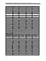
Revision History
The following lists the additions, deletions and modifications in this manual at each revision.
Date
January 2002
Version
1.0
Revised Sections
Complete this manual
January 2004
1.1
Modify “The Rear Panel”
“DATALOCK”
“COUPLE Mode of Output (AC+DC, AC, DC)
“Programmable Output Impedance”
“THREE PHASE MODE”
“PARALLEL MODE”
“Synthesis Waveform”
“Interharmonics Waveform”
“The GPIB Capability of the AC Source”
vii
PROGRAMMABLE AC SOURCE 61501/61502/61503/61504 User’s Manual
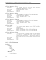
Table of Contents
1.
General Information .................................................................................................1-1
1.1 Introduction .............................................................................................................1-1
1.2 Key Features............................................................................................................1-1
1.3 Specifications ..........................................................................................................1-1
1.4 Names of Parts ........................................................................................................1-3
1.4.1
1.4.2
2.
2.1
2.2
2.3
The Front Panel .......................................................................................................... 1-3
The Rear Panel ........................................................................................................... 1-5
Installation .................................................................................................................2-1
Inspection ................................................................................................................2-1
Preparation for the Use............................................................................................2-1
Requirements of Input Power..................................................................................2-1
2.3.1
2.3.2
Ratings........................................................................................................................ 2-1
Input Connection ........................................................................................................ 2-1
2.4
2.5
2.6
2.7
Output Connection ..................................................................................................2-3
Remote Sense Connection.......................................................................................2-3
The Procedures of Power-on ...................................................................................2-4
I/O Connectors (Option)..........................................................................................2-6
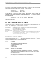
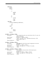
3.
Local Operation.........................................................................................................3-1
3.1 Introduction .............................................................................................................3-1
3.2 Operation through Keypad and RPG ......................................................................3-1
3.3 MAIN PAGE (Output Setting and Measurement) ..................................................3-4
3.4 CHOICE PAGE (Functional List Choice) ..............................................................3-5
3.5 SETUP Functional List ...........................................................................................3-5
3.5.1
3.5.2
3.5.3
3.5.4
3.5.5
3.5.6
3.5.7
3.5.8
3.6
CONF Functional List...........................................................................................3-10
3.6.1
3.6.2
3.6.3
3.6.4
3.6.5
3.7
4.
COUPLE Mode of Output ( AC+DC, AC, DC )...................................................... 3-17
OUTPUT DEGREE ................................................................................................. 3-19
Programmable Output Impedance............................................................................ 3-19
Slew Rate of Output Transient ................................................................................. 3-20
THREE PHASE MODE........................................................................................... 3-22
PARALLEL MODE................................................................................................. 3-25
Save and Recall .....................................................................................................3-27
3.8.1
3.8.2
3.9
REMOTE INHIBIT.................................................................................................. 3-11
EXT. V, COUPLE.................................................................................................... 3-12
WAVEFORM GENERATOR ................................................................................. 3-13
POWER ON STATUS ............................................................................................. 3-14
GPIB Address, RS-232C.......................................................................................... 3-15
OUTPUT Functional List......................................................................................3-16
3.7.1
3.7.2
3.7.3
3.7.4
3.7.5
3.7.6
3.8
RANGE ...................................................................................................................... 3-6
Vac LIMIT ................................................................................................................. 3-7
Vdc LIMIT (+), Vdc LIMIT (-) ................................................................................. 3-7
I LIMIT, DELAY....................................................................................................... 3-8
OUTPUT RELAY...................................................................................................... 3-8
BUZZER .................................................................................................................... 3-9
DATALOCK.............................................................................................................. 3-9
Is START, Is INTERVAL ....................................................................................... 3-10
Save and Recall Output Setting................................................................................ 3-27
Save and Recall System Data................................................................................... 3-29
Protection ..............................................................................................................3-30
Calibration .................................................................................................................4-1
ix
PROGRAMMABLE AC SOURCE 61501/61502/61503/61504 User’s Manual
4.1
4.2
Introduction .............................................................................................................4-1
MANUAL CALI Functional List............................................................................4-1
4.2.1
4.2.2
4.2.3
Output Voltage and Voltage Measurement Calibration ............................................. 4-3
Current Measurement Calibration .............................................................................. 4-5
External Vref Calibration ........................................................................................... 4-7
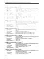
5.
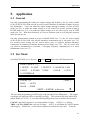
Application.................................................................................................................5-1
General ....................................................................................................................5-1
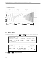
List Mode ................................................................................................................5-1
Pulse Mode..............................................................................................................5-4
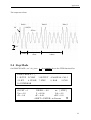
Step Mode ...............................................................................................................5-7
Harmonic Measurement ........................................................................................5-10
Synthesize Waveform ...........................................................................................5-12
Interharmonics Waveform.....................................................................................5-14
6.
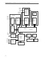
Theory of Operation..................................................................................................6-1
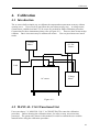
6.1 General ....................................................................................................................6-1
6.2 Description of Overall System ................................................................................6-1
7.
Self-test and Troubleshooting ..................................................................................7-1
7.1 General ....................................................................................................................7-1
7.2 Self-test....................................................................................................................7-1
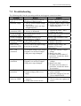
7.3 Troubleshooting ......................................................................................................7-3
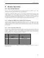
8.
Remote Operation .....................................................................................................8-1
8.1 General Information ................................................................................................8-1
5.1
5.2
5.3
5.4
5.5
5.6
5.7
8.1.1
8.1.2
8.2
8.3
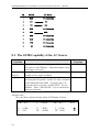
The GPIB Capability of the AC Source ..................................................................8-2
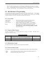
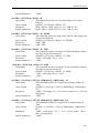
Introduction to Programming ..................................................................................8-3
8.3.1
8.3.2
8.3.3
8.3.4
8.3.5
8.4
8.5
8.6
Setting the GPIB Address and RS-232C Parameters ................................................. 8-1
Wire Connection of RS-232C .................................................................................... 8-1
Conventions................................................................................................................ 8-3
Numerical Data Formats ............................................................................................ 8-3
Boolean Data Format ................................................................................................. 8-3
Character Data Format ............................................................................................... 8-3
Basic Definition.......................................................................................................... 8-4
Traversal of the Command Tree..............................................................................8-5
Execution Order ......................................................................................................8-5
The Commands of the AC Source...........................................................................8-6
8.6.1
8.6.2
Common Command Dictionary ................................................................................. 8-6
Instrument Command Dictionary............................................................................... 8-8
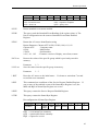
8.7 Command Summary..............................................................................................8-33
Appendix A: Pin Assignment of TTL SIGNAL................................................................. A-1
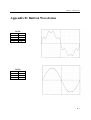
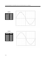
Appendix B: Built-in Waveforms ....................................................................................... B-1
x
General Information
1. General Information
1.1 Introduction
The series of Chroma AC source 61501/61502/61503/61504 are high efficiency AC power
source which provide sine wave output with low distortion, and accurate measurement of
power. The DSP microprocessor generates accurate, stable output voltage and frequency.
The PWM design of power stage allows for full volt-ampere into loads. The front panel has
both RPG (rotary pulse generator) and keypad controls for setting the output voltage and
frequency. The LCD provides a complete operating state of the unit to the user. Remote
programming is accomplished either through the GPIB bus or the RS-232C serial port.
1.2 Key Features
A. Configuration
Local operation from the keypad on the front panel.
Remote operation via GPIB or RS-232C interface.
Protection against Over-power, Over-Current, Over-temperature, Fan-fail.
Temperature-controlled fan speed.
Built-in output isolation relays.
B. Input/Output
Selective output voltage with full scale of 150V/300V/Auto.
Remote control by the use of analog voltage reference.
Universal of input voltage range 90Vac ~ 250Vac.
Measurement of V, I, P, CF, PF, Idc, Vdc, Ipk, Is, VA and VAR.
Remotely inhibited control.
AC ON/OFF output signal.
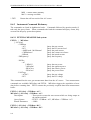
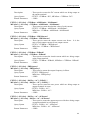
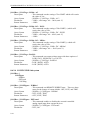
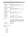
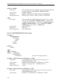
1.3 Specifications
The operation specifications of the model 61501/61502/61503/61504 are listed below (on the
next page). All specifications have been tested according to the standard Chroma test
procedures. All specifications are based on a remote sense connection, 25 ± 1°C, and
resistor load unless specified otherwise.
1-1
PROGRAMMABLE AC SOURCE 61501/61502/61503/61504 User’s Manual
Model
61501
61502
61503
AC OUTPUT RATING
Max. power
500 VA
1K VA
1.5K VA
Voltage
Range
150V / 300V / Auto
Accuracy
0.2%+0.2%F.S. 0.2%+0.2%F.S. 0.2%+0.2%F.S.
Resolution
0.1 V
0.1 V
0.1 V
Distortion
0.3% @50/60Hz 0.3% @50/60Hz 0.3% @50/60Hz
1% 15- 1K Hz 1% 15- 1K Hz 1% 15- 1K Hz
Line regulation
0.1%
0.1%
0.1%
Load regulation
0.2%
0.2%
0.2%
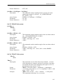
Temp. coefficient
0.02% per degree from 25°C
Maximum current
r.m.s.
4A / 2A
8A / 4A
12A / 6A
peak
24A / 12A
48A / 24A
72A / 36A
Frequency
Range
DC, 15-1K Hz DC, 15-1K Hz DC, 15-1K Hz
Accuracy
0.15%
0.15%
0.15%
DC OUTPUT RATING
Power
250W
500W
750W
Voltage
212V / 424V
212V / 424V
212V / 424V
Current
2A / 1A
4A / 2A
6A / 3A
OUTPUT IMPEDANCE
Range
0.0Ω+0.0mH - 1.0Ω+1.0mH
HARMONICS & SYNTHESIS SIMULATION
Bandwidth
50Hz / 60Hz
40 order
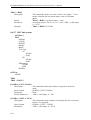
INPUT RATING
Voltage range
90-250V
90-250V
90-250V
Frequency range
47-63 Hz
47-63 Hz
47-63 Hz
Current
8A Max.
16A Max.
21A Max.
Power factor
0.97 Min.
0.98 Min.
0.98 Min.
MEASUREMENT
Voltage
Range
150V / 300V
150V / 300V
150V / 300V
Accuracy
0.2%+0.2%F.S. 0.2%+0.2%F.S. 0.2%+0.2%F.S.
Resolution
0.1 V
0.1 V
0.1 V
Current
Range (peak)
24A
48A
72A
Accuracy (r.m.s.) 0.4%+0.3%F.S. 0.4%+0.3%F.S. 0.4%+0.3%F.S.
Accuracy (peak) 0.4%+0.6%F.S. 0.4%+0.6%F.S. 0.4%+0.6%F.S.
Resolution
0.01 A
0.01 A
0.01 A
Power
Accuracy
0.4%+0.4% F.S. 0.4%+0.4% F.S. 0.4%+0.4% F.S.
Resolution
0.1 W
0.1 W
0.1 W
OTHERS
Efficiency
68 %
77 %
78 %
Size (W×H×D)
483 mm × 134 mm × 610 mm
1-2
61504
2K VA
0.2%+0.2%F.S.
0.1 V
0.3% @50/60Hz
1% 15- 1K Hz
0.1%
0.2%
16A / 8A
96A / 48A
DC, 15-1K Hz
0.15%
1K W
212V / 424V
8A / 4A
90-250V
47-63 Hz
28A Max.
0.98 Min.
150V / 300V
0.2%+0.2%F.S.
0.1 V
96A
0.4%+0.3%F.S.
0.4%+0.6%F.S.
0.01 A
0.4%+0.4% F.S.
0.1 W
80 %
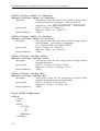
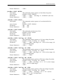
General Information
Weight
20 Kg
Protection
Temperature Range
Operation
Storage
Humidity
Safety & EMC
20 Kg
21 Kg
UVP, OCP, OPP, OTP, FAN
21 Kg
0 °C to 40 °C
-40 °C to 85 °C
30 % to 90 %
FCC 15J class A, CE
Remarks
*1: Maximum distortion is tested on output 125VAC (150V RANGE) and 250VAC
(300V RANGE) with maximum current to linear load.
*2: Load regulation is tested with sinewave and remote sense.
*3: Efficiency is tested on input voltage 110V.
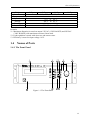
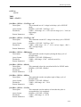
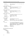
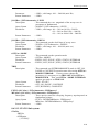
1.4
Names of Parts
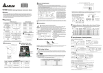
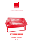
1.4.1 The Front Panel
1
11
3
4
5
2
7
6
8
10
9
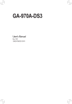
Figure 1-1 The Front Panel
1-3
PROGRAMMABLE AC SOURCE 61501/61502/61503/61504 User’s Manual
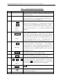
Table 1-1 The Description of the Front Panel
Item
Symbol
Description
1
Display: The LCD is to display configuration, output setup, and
measurement results.
2
Indicator LED: "OUT" and "SHIFT", for showing activation of
output and shift mode, are available which are located on the
keypad area next to the corresponding keys.
3
t
----------or--------PAGE
Cursor moving keys: These two keys are to move the cursor to
different directions respectively. In normal mode, pressing any
of these two keys will change the place of the cursor. Under
shift mode, these keys enable the LCD display to change to last
page or next page if there are
or
patterns in right-down side
of display.
PAGE
4
PAGE/EXIT
-----------or---------SAVE
5
/-----------or---------RECALL
6
8
Backspace and Minus command key: Pressing this key will
erase the keyin number. Or it may show " - ", if no number is
in front of cursor. Under shift mode, pressing the key on
MAIN PAGE, the user can recall the output setting (see 3.8.1).
If pressing the key on CHOICE PAGE, the user can recall
system data (see 3.8.2).
OUT/QUIT command key: Pressing this key may enable the ac
source output voltage or quit the output voltage.
OUT/QUIT
7
PAGE or EXIT command key: Pressing this key will make the
LCD display switching between MAIN PAGE and CHOICE
PAGE. Or change to CHOICE PAGE in each functional list.
Under shift mode, pressing this key on MAIN PAGE, the uses
can save the output setting (see 3.8.1). If pressing the key on
CHOICE PAGE, the user can save system data (see 3.8.2).
Shift mode selection key: Pressing this key will switch the ac
source from normal operational mode to the shift mode.
SHIFT
Numeric and decimal keys: The user can program numeric data
by pressing the digital keys and the decimal key. Under shift
-------------or------------ mode, pressing • acts the HELP function. The LCD display
will show more information about cursor locating place.
HELP
0
to
9 , and
9
ENTER
•
ENTER key: It is to confirm the setting of parameters.
10
RPG: The user can input programming data or options by turning
the RPG to the desired ones.
11
Main power switch: It is to power on or off.
1-4
General Information
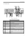
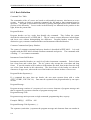
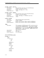
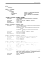
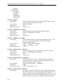
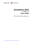
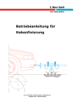
1.4.2 The Rear Panel
2
1
8
7
3
6
4
5
9
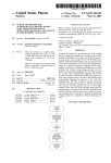
Figure 1-2 The Rear Panel
Table 1-2 The Description of the Rear Panel
Item
Name
1
Label
2
3
4
5
6
7
8
9
Description
The label includes model number, series number of the AC source.
The BNC connector inputs control waveform amplitude from
Ext. Ref.
external analog signal.
The 9-pin, D-type female connector transfers control commands to
RS-232C
and from the remote PC for remote operation.
A remote controller using GPIB bus is connected to the AC source
GPIB Connector
through this connector for remote operation.
TTL SIGNAL
The 9-pin, female connector transfers control signals (fault_out,
remote inhibit, and AC_ON).
The BNC connectors SCLK and PWM are for AC source parallel
SCLK, PWM, SYNC connectivity only. SYNC transfers a pulse signal synchronously
when output changes. It also sends synchronizing signal for
3-phase mode operation.
Output Connector This connector outputs power to the loading device.
It senses directly at the terminals of the load to eliminate any
voltage drop on the connecting cable. Make sure of connecting
Remote Sense
the terminal “SL” of the remote sense connector to the terminal “L”
Connector
of the load, and the “SN” to the “N” of the load. Reverse polarity
is not allowed.
Power Line in
Power line input is connected to the AC source through this
Connector
connector.
1-5
Installation
2. Installation
2.1 Inspection
After unpacking the instrument, please inspect any damage that may have occurred during the
shipment. Save all packing materials in case the instrument has to be returned one day.
If any damage is found, please file a claim with the carrier immediately. Do not return the
instrument to the factory without obtaining the prior RMA acceptance from Chroma.
2.2 Preparation for the Use
In the beginning, the instrument must be connected with an appropriate AC line input. Then,
since fans intelligently cool it, it must be installed in sufficient space for circulation of air. It
should be used in an area where the ambient temperature does not exceed 40°C.
2.3 Requirements of Input Power
2.3.1 Ratings
Input Voltage Range
Input Frequency
Max. Current
:
:
:
90 ~ 250 Vac, single phase
47-63 Hz
61501 : 8 A
61502 : 16 A
61503 : 21 A
61504 : 28 A
Caution: The AC source will be damaged if it is operated at an input voltage that is outside
its configured input range.
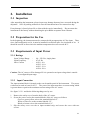
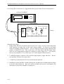
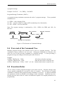
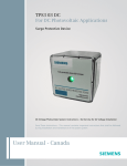
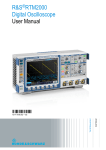
2.3.2 Input Connection
The input terminal block is located on the rear downside panel of the instrument. The power
cord must be rated at least for 85°C. The power line input must have a current rating which
is greater than or equal to the maximum current rating of the AC source.
See figure 2.3.2.1 and do the following things one by one:
1.
2.
3.
Remove the safety cover from the back of the AC source.
Screw the power cord to the terminal blocks of the AC source as follows:
Green or green/yellow wire to the terminal labeled “G”.
White or blue wire to the terminal labeled “N”.
Black or brown wire to the terminal labeled “L”.
Slip the safety cover over the ac input terminal strip, and secure the cover with two
screws.
2-1
PROGRAMMABLE AC SOURCE 61501/61502/61503/61504 User’s Manual
*** WARNING ***
To protect the operators, the wire connected to the GND terminal must be
connected to the earth ground. Under no circumstances shall this AC
source be operated without an adequate ground connection.
Installation of the power cord must be done by a professional and in accordance with local
electrical codes.
Figure 2.3.2.1 Input Connection
Figure 2.3.2.2 Input Terminal Cover
2-2
Installation
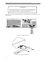
2.4 Output Connection
The output terminal block is located on the rear of the AC source. Load connecting to the
"N" and "L" is done at the output terminals. To meet the safety requirements, the safety
cover must be fasten. The wires to the load must be sufficiently large gauges, so they will
not overheat while carrying the output current. Please see figure 2.5.1 on the next page.
*** NOTICE ***
Output terminal labeled "L" is the "+" terminal, terminal labeled "N" is the "-"
terminal when output voltage contains DC composition.
2.5 Remote Sense Connection
The remote sense function of the AC source monitors the voltage at the load instead at the
output terminal of the AC source. It ensures the delivery of accurate voltage as programmed
at the load by automatically compensating the output voltage drop over the connecting cable.
Remove the iron chip from the “SN” and “SL” terminals, connect the remote sense to the load
as shown in Figure 2.5.1. Because the sensing leads carry only a few milliamperes, the
wires for sensing are much lighter than the load leads. The sensing leads are part of the
feedback path of the AC source, so they must be kept at a low resistance in order to maintain
the best performance. Connect the sensing leads carefully so that they will not be
open-circuited. If the sensing leads are left unconnected or become open-circuited during
operation, the AC source will disable the output. The sensing leads must be a twisted pair to
minimize the pickup of external noise. The sensing leads need to be connected to the load as
close as possible.
2-3
PROGRAMMABLE AC SOURCE 61501/61502/61503/61504 User’s Manual
Figure 2.5.1 Output & Remote Sense Connection
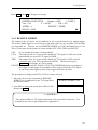
2.6 The Procedures of Power-on
*** WARNING ***
Before turning on the instrument, all protective earth terminals, extension cords, and
devices connected to the instrument must be connected to a protective earth ground.
Any interruption of the protective earth grounding will cause a potential shock hazard
that could result in personal injury.
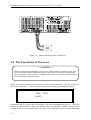
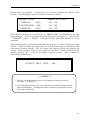
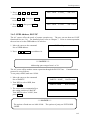
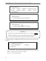
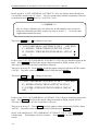
Apply the line power and turn on the power switch on the front panel. The AC source will
do a series of self-tests. The LCD on the front panel will light up and display as below :
SELF TEST
WAIT . . . . . .
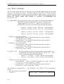
Meanwhile, the AC source does the memory, data and communication self-test. After the
routines of the self-test be done, the display shows the MODEL number, and the serial
number of the AC source, and it shows an “OK” at the right side of each test item indicating
2-4
Installation
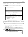
that the item is no problem. It takes about six seconds to complete the routines of the
self-test. Then the display shows the versions of software as below.
MODEL : 61502
1. DISPLAY
< OK >
2. WAVEFORM < OK>
< OK >
3. REMOTE
SERIAL NO : 123456
Ver : 1.01
Ver : 1.02
Ver : 1.03
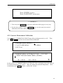
If any failure is detected on a certain item, an “ERROR CODE” will be shown at the right
side of that item. The error messages and trouble-shooting are shown on 7.2. The test item
" 3. REMOTE " shows " < EMPTY>, if the option board ( with GPIB and RS-232 ) is not
connected.
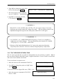
After finishing memory, data and communication self-test, the AC source do the power output
self-test. In this procedure, the output relays are in OFF status to sure not harming the load
connecting on output terminal. The AC source will program 300Vac and measure the
voltage. If the measured voltage is over 300V±5V, the power self-test is failed, and the
display will show "NG". If it's ok, the display is shown as below. Then, it changes to
MAIN PAGE automatically.
OUTPUT
SELF
TEST
< OK >
*** NOTICE ***
1. The user can do diagnosis if error or NG happens in power-on self-test
procedure. Please see 7.2.
2. The inner digital circuit of AC source maybe not reset if turn off power then
turn on immediately. Waiting more than 3 seconds is suggested to turn on
power after turning off.
2-5
PROGRAMMABLE AC SOURCE 61501/61502/61503/61504 User’s Manual
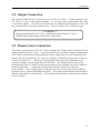
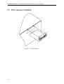
2.7 I/O Connectors (Option)
Figure 2.7.1 Option Board
2-6
Local Operation
3. Local Operation
3.1 Introduction
The AC source can be configured to operate in local or remote mode. The operation in
remote mode through a remote GPIB controller or RS-232C will be described in Chapter 8.
In this section the operation in local mode through the keypad on the front panel for data entry
and test is going to be described. The AC source is configured for local operation when it is
turned on.
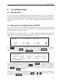
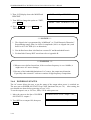
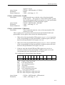
3.2 Operation through Keypad and RPG
The AC source provides the user-friendly programming interface using the keypad and RPG
(Rotary Pulse Generator) on the front panel to the user. Each display of the LCD on the AC
source represents an operational menu.
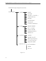
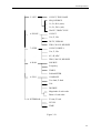
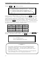
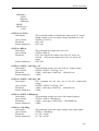
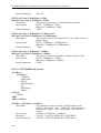
The command tree is shown in Figure 3.2.1. Before describing each menu, the following
shows how to use keypad and RPG to set command. When the procedure of power-on is
finished (see 2.6), the display will show MAIN PAGE as below.
Vac = 0.0
F
= 60.00
V = 0.00
P = 0.0
F = 0.00
PF = 0.000
Vdc = 0.0
I = 0.00
CF = 0.00
H
S
T
Press ,
to move cursor to choose the item. Use numeric and decimal keys or RPG to
set value, then press ENTER to confirm. The user can press PAGE/EXIT to change to
CHOICE PAGE as below. Or press PAGE/EXIT again to return to MAIN PAGE.
PAGE CHOICE = 1_
1. SETUP 2.CONF 3.OUTPUT
6. PULSE 7. STEP
5. LIST
10. INTERHAR
4. MANUAL CALI
8. HAR
9. SYN
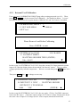
In CHOICE PAGE, the user can press numeric key then ENTER to choose the functional lists.
After entering each functional list, press ,
to move cursor to destination. If number
expresses the settings, the user can use numeric and decimal keys or RPG to set value, then
press ENTER to confirm. If the settings are expressed by words, the user can turn RPG to
choice, then press ENTER to confirm.
If there are
or
patterns in right-down side of display, it means there are functional list
on last page or next page. The user can press SHIFT then
or
to change page. If finish
the setting, press PAGE/EXIT to return to CHOICE PAGE.
3-1
PROGRAMMABLE AC SOURCE 61501/61502/61503/61504 User’s Manual
MAIN PAGE (output setting and measurement)
PAGE CHOICE
1. SETUP
RANGE
Vac LIMIT
Vdc LMT (+), Vdc LMT (-)
I LIMIT, DELAY(s)
BUZZER
OUTPUT RELAY
DATALOCK
Is START, Is INTERVAL
2. CONF
REMOTE INHIBIT
EXT. V, COUPLE
WAVEA, WAVEB
POWER ON STATUS
GPIB, RS-232
3. OUTPUT
COUPLE
DEGREE: ON, OFF
PROG Output Impedance
Vs, Fs, DCs (slew rate)
PARALLEL MODE
4. MANUAL CAL
V OUT AND MEAS.
I MEAS.
EXT Vref.
Figure 3.2.1
3-2
Local Operation
5. LIST
COUNT, TRIG, BASE
SEQ, DEGREE
Vs, Fs, DCs (start)
Ve, Fe, DCe (end)
WAVE, TIME/CYCLE
6. PULSE
COUNT
Vac, F, Vdc
DUTY, PERIOD
TRIG, WAVE, DEGREE
7. STEP
COUNT, DWELL
Vac, F, Vdc
dV, dF, dDC
TRIG, WAVE, DEGREE
8. HAR
SOURCE
Frequency
TIMES
PARAMETER
9. SYN
COMPOSE
Vac-fund, F-fund
Vdc
DEGREE
Magnitude of each order
Phase of each order
10. INTERHAR
Fi start, Fi end
LEVEL
TIME
Figure 3.2.1
3-3
PROGRAMMABLE AC SOURCE 61501/61502/61503/61504 User’s Manual
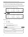
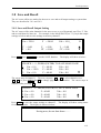
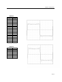
3.3 MAIN PAGE (Output Setting and Measurement)
When the user turn on the AC source, after self-test steps, the display shows the MAIN PAGE.
The upper line of display shows the output settings. The state of default output settings can
be set on POWER ON STATUS in CONF functional list (see 3.6.3). The lower lines show
the measurements of AC source output. Please see the following.
Vac = 0.0
F
V = 0.00
P = 0.0
Press SHIFT , then
or
= 60.00
F = 0.00
PF = 0.000
Vdc = 0.0
L
S
T
I = 0.00
CF = 0.00
to change to next page.
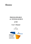
Please see the following.
Vac = 0.0
F
Vdc = 0.0
L
Vdc = 0.00
Is = 0.0
Idc = 0.00
VA = 0.0
Ip = 0.0
VAR = 0.0
S
T
= 60.00
On the right-up side of display, a letter "L" shows the status of RANGE (see 3.5.1). The
definition of letters:
L : 150V RANGE
H : 300V RANGE
A : AUTO RANGE
The definitions of output setting parameters:
Vac
F
Vdc
: It is the AC composition of output voltage in Volts.
: It is the output frequency in Hertz.
: It is the DC composition of output voltage in Volts.
Press OUT/QUIT then the AC source output the voltage set in Vac, F, Vdc.
again, then the AC source quit the output voltage.
Press OUT/QUIT
*** NOTICE ***
When COUPLE = AC+DC, the output is the combination of Vac and Vdc. But the
combination of peak voltage can not exceed the limit of each range (150V RANGE:
212.1V, 300V RANGE : 424.2V). If it is happened, the output voltage will quit to
0V automatically, and show the protection condition.
3-4
Local Operation
The definitions of measurement parameters:
V
F
I
P
PF
CF
Vdc
Idc
Ip
Is
VA
VAR
: It is the measurement readings of Voltage in Volts. (True RMS measurement)
: It is the output Frequency in Hertz.
: It is the measurement readings of Current in Amperes. (True RMS measurement)
: It is the true Power measurement in Watts.
: It is the Power Factor, and its calculation formula = true power/ (Vrms × Irms)
: It is the Crest Factor, and its calculation formula = Ipeak/Irms.
: It is the DC composition measurement readings of Voltage in Volts.
: It is the DC composition measurement readings of Current in Amperes.
: It is the peak current measurement in Amperes.
: It is I surge, and only measured from the occurrence of output transition as defined
in 3.5.8.
It is Apparent Power in Watts, and its calculation formula = Vrms × Irms.
: Its calculation formula = VA2 − P 2
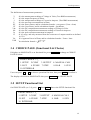
3.4 CHOICE PAGE (Functional List Choice)
If displays on MAIN PAGE or on functional list, press PAGE/EXIT to change to CHOICE
PAGE as below:
PAGE CHOICE = 1_
1. SETUP 2.CONF 3.OUTPUT
6. PULSE 7. STEP
5. LIST
10. INTERHAR
4. MANUAL CALI
8. HAR
9. SYN
Users can press 0 - 9 to choose operational list item, then press ENTER to confirm it.
The display will switch to MAIN PAGE when press PAGE/EXIT on CHOICE PAGE.
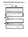
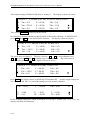
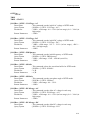
3.5 SETUP Functional List
On CHOICE PAGE (see 3.4), press 1 then ENTER , choose the SETUP functional list.
PAGE CHOICE = 1_
1. SETUP 2.CONF 3.OUTPUT
6. PULSE 7. STEP
5. LIST
10. INTERHAR
4. MANUAL CALI
8. HAR
9. SYN
3-5
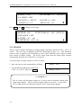
PROGRAMMABLE AC SOURCE 61501/61502/61503/61504 User’s Manual
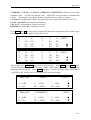
RANGE = 150V
Vac LIMIT = 300V
Vdc LMT (+) = 424.2 V
I LIMIT (A) = 0.0
Press SHIFT , then
WAVEFORM = A
[ SETUP ]
Vdc LMT (-) = 0.0V
DELAY (S) = 0.0
T
to change to next page.
BUZZER = ON
OUTPUT RELAY = ON
DATALOCK = OFF
Is START = 0.0
ms
Is INTERVAL = 50.0 ms
[ SETUP ]
S
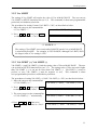
3.5.1 RANGE
The AC source supplies full range of output voltage with three options of 150 V, 300 V, or
AUTO. The user can set RANGE on SETUP functional list (see 3.5). This parameter
controls relays to parallel (150V RANGE) or series (300V RANGE) power stages to obtain
more current or higher voltage. The AUTO range means that the output range switches
automatically between 150 V and 300 V as required.
To set the range of output voltage as AUTO as below :
1. Move the cursor to the command line of Range.
Range = 300V_
2. Turn the RPG to change the option from
“300V” to “AUTO”, then press ENTER.
Range = AUTO
*** NOTICE ***
The AC source will set output voltage as 0 V first in order to eliminate voltage spike
when range changes. Then, it will set output voltage as set value. It may cause
UUT to shut down or get bad if the output is active, when range changes.
3-6
Local Operation
3.5.2 Vac LIMIT
The setting of Vac LIMIT will restrict the value of Vac in MAIN PAGE. The user can set
Vac LIMIT on SETUP functional list (see 3.5). This command is about user-programmable
protection, not hardware protection.
The procedures for setting Current Vac LIMIT = 120V, are described as below:
1. Move the cursor to the command line
of “Vac LIMIT = ”.
Vac LIMIT = 300.0_
2. Press 1 , 2 , 0 then press ENTER
to change the value to “120.0”.
Vac LIMIT(A) = 120.0
*** NOTICE ***
The setting of Vac LIMIT is not restricted by RANGE, but the Vac on MAIN PAGE
is restricted by RANGE. For example, in 150V RANGE, although Vac LIMIT=200V,
the largest value of Vac setting is 150V.
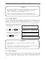
3.5.3 Vdc LIMIT (+), Vdc LIMIT (-)
Vdc LIMIT (+) and Vdc LIMIT (-) limit the setting value of Vdc on MAIN PAGE. The user
can set both on SETUP functional list (see 3.5). The setting value of Vdc can not be higher
than Vdc LIMIT (+), or can not be lower than Vdc LIMIT (-). Vdc LIMIT (+) must be
positive or zero, Vdc LIMIT (-) must be negative or zero. This command is about
user-programmable protection, not hardware protection.
The procedures of setting Vdc LMT (+)=200V, Vdc LMT (-)=-50V, are described as below :
1. Move the cursor to the command line
of “Vdc LIMIT(+) = ”.
Vdc LMT(+) = 424.2_ Vdc LMT(-) = 0.0
2. Press 2 , 0 , 0 then press ENTER
to change the value to “200.0”.
3. The cursor moves to the command line
of “Vdc LIMIT(-) = ” automatically.
/ - , 5 , 0 then press
ENTER to change the value to “-50.0”.
Vdc LMT(+) = 200.0
Vdc LMT(+) =200.0
Vdc LMT(-) = 0.0_
Vdc LMT(-) = -50_
4. Press
Vdc LMT(+) = 200.0 Vdc LMT(-) = -50.0
3-7
PROGRAMMABLE AC SOURCE 61501/61502/61503/61504 User’s Manual
*** NOTICE ***
1. The setting of Vdc LIMIT is not restricted by RANGE, but the Vdc on MAIN PAGE
still restricted by RANGE. For example, in 150V RANGE, although Vdc
LIMIT = 250V the largest value of Vac setting is 212.1V.
2. When AC source output contains Vdc, it's better to restrict the value of Vdc.
It may cause damage if output polarity is reverse, especially the load is polar.
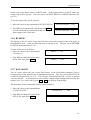
3.5.4 I LIMIT, DELAY
Limitation of output RMS current, and delay time is the parameter for triggering over current
protection. The user can set both on SETUP functional list (see 3.5). The discussion of
limitation in this command is about user-programmable protection, not hardware protection.
The procedures of setting Current limit = 4A, Delay time = 1 sec., are described as below:
1. Move the cursor to the command line
of “I LIMIT(A) = ”.
I LIMIT(A) = 0.00_ DELAY(S) = 0.0
2. Press 4 , then press ENTER to change
the value to “4.00”.
I LIMIT(A) = 4_
DELAY(S) = 0.0
3. The cursor moves to the command line
of “DELAY(S) = ” automatically.
I LIMIT(A) = 4.00
DELAY(S) = 0.0_
4. Press 1 , ENTER to change the
value to “1.0”.
I LIMIT(A) = 4.00
DELAY(S) = 1.0_
*** NOTICE ***
1. When " I LIMIT (A) = 0 ", means the limitation of output current is equal to
specification.
2. DELAY time is valid for eliminating transient current spike, but not work when the
output current is over specification. The resolution is 0.5s.
3.5.5 OUTPUT RELAY
There are relays on the output of the AC source for the connection to load. When output
relay is “ON”, it means that the output relay is closed in spite of that the output status of the
AC source is in QUIT mode. When output relay is “OFF”, it means that the output relay is
3-8
Local Operation
closed only as the output status is in RUN mode. If the output status is in QUIT mode, the
output relay will be opened. The user can set OUTPUT RELAY on SETUP functional list
(see 3.5).
To set the output relay as ON as below:
1. Move the cursor to the command of OUTPUT RELAY.
OUTPUT RELAY = OFF_
2. Turn RPG to set output relay ON, then press ENTER .
A click sound will be produced from the AC source
when output relay is activated.
OUTPUT RELAY = ON
3.5.6 BUZZER
The buzzer of the AC source beeps when the user presses the keypad on the front panel, or
turns the RPG knob. If the user does not need it, can turn it off. The user can set BUZZER
on SETUP functional list (see 3.5).
To turn off the buzzer as follows:
1. Move the cursor to the command line
of “Buzzer=”.
2. Turn RPG to change the option from
ON to OFF, then press ENTER .
Buzzer = ON_
Buzzer = OFF
3.5.7 DATALOCK
The AC source allows the user to lock data entries, so the pre-defined parameters can be
protected from being modified by an unauthorized person. The user can set DATALOCK
on SETUP functional list (see 3.5). The user also can set DATALOCK = FUNC to operate
“One-key Recall”. It means the user can recall the voltage output setting which stored in the
memory (see 3.8.1) only need to press 1 - 9 key directly in Main Page.
The procedures of the setting data lock are shown as below:
1. Move the cursor to the command line
of “DATALOCK=”.
DATALOCK = OFF_
2. Turn RPG to change the option from
OFF to ON, then press ENTER .
DATALOCK = ON
3-9
PROGRAMMABLE AC SOURCE 61501/61502/61503/61504 User’s Manual
*** NOTICE ***
1. The user must select OFF to unlock.
2. If users use FUNC, please be sure the voltage output settings stored in
the memory. Unexpected voltage output may damage the UUT.
3.5.8 Is START, Is INTERVAL
Is is the surge peak current of AC source output shown in MAIN PAGE. Is measurement
starts at Is START after output voltage transition. The length of measurement time is Is
INTERVAL. The user can set both on SETUP functional list (see 3.5).
The procedures of setting Is START = 10 ms, Is INTERVAL = 200 ms, are described as
below:
1. Move the cursor to the command line
Is START= 0.0_ ms
of “Is START = ”.
2. Press 1 , 0 then press ENTER to
change the value to “10.0”.
Is START = 10.0
3. The cursor moves to the command line
of “Is INTERVAL = ” automatically.
Is INTERVAL = 50.0_
ms
4. Press 2 , 0 , 0 then press ENTER
to change the value to “200.0”.
Is INTERVAL = 200.0_
ms
ms
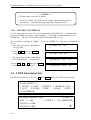
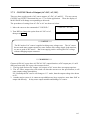
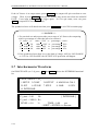
3.6 CONF Functional List
On CHOICE PAGE (see 3.4), press 2 then ENTER , choose the CONF functional list.
PAGE CHOICE = 2_
1. SETUP 2.CONF 3.OUTPUT
6. PULSE 7. STEP
5. LIST
10. INTERHAR
4. MANUAL CALI
8. HAR
9. SYN
REMOTE INHIBIT = OFF
EXT. V =OFF
COUPLE =
WAVE A = SINE
WAVE B = SINE
3-10
[ CONF ]
AC-AMPLIFIER
T
Local Operation
Press SHIFT , then
to change to next page.
POWER ON STATUS :
Output = OFF
[ CONF ]
Vac = 0.0
F = 60.00
Vdc = 0.0
ADDR = 1
PARITY = NONE
BAUD = 9600
S
3.6.1 REMOTE INHIBIT
The output of the AC source can be inhibited by the external control or by manual trigger.
The remote inhibit signal is received from 9-pin male connector on rear panel TTL SIGNAL
(see Appendix A). The user can set REMOTE INHIBIT on CONF functional list (see 3.6).
There is four states for the feature of remote inhibit: OFF, LIVE, TRIG and EXCITE.
OFF
LIVE
: It is to disable the feature of remote inhibit.
: The output of the AC source will be disabled if TTL signal is LOW, but will be
automatically recovered if TTL signal is HIGH.
TRIG : The output of the AC source will be disabled if TTL signal is LOW, and will
remain the state even TTL signal becomes HIGH. The user has to press
OUT/QUIT to restart the AC source output.
EXCITE : When users run LIST, PULSE, STEP, SYN, INTERHAR mode (see chapter 5),
the trigger on and trigger off commands will be triggered form this TTL signal.
A low active pulse signal (at least 60us) trigger the actions by turns.
The procedures of setting from OFF to LIVE are shown as below:
1. Move the cursor to the command of "REMOTE
INHIBIT" to set inhibition by the TTL signal from
the external control.
2. Turn RPG to change the option from OFF to LIVE,
then press ENTER .
REMOTE INHIBIT =OFF_
REMOTE INHIBIT =LIVE
*** NOTICE ***
The remote inhibit is a TTL signal transferred via the special I/O connector.
detailed please refers to pin assignment in Appendix A.
For
3-11
PROGRAMMABLE AC SOURCE 61501/61502/61503/61504 User’s Manual
3.6.2 EXT. V, COUPLE
The AC source allows the user to make use of the controlled analog signal from external
devices for the setting of its output. The BNC connector of the EXT Vref on the rear panel
lets the user apply signal to the AC source for the setting of output voltage. The user can set
EXT. V and COUPLE on CONF functional list (see 3.6). There are two coupling mode to
present AC source output from external V reference: AC_AMPLIFIER and
DC_LEVEL_CTL.
AC_AMPLIFIER : The output voltage (Vout) is the synthesis of voltage programming on
MAIN PAGE and the amplification of external V reference with
voltage range from -10 V to 10 V. When Vac=0 and Vdc=0 on
MAIN PAGE, Vout can be calculated using the following formula:
Vout (dc) = Vref (dc) / 10 Vdc × 424.2 Vdc
Vout (dc) = Vref (dc) / 10 Vdc × 212.1 Vdc
(300V RANGE)
(150V RANGE)
Vout (ac) = Vref (ac) / 7.072 Vac × 300 Vac
Vout (ac) = Vref (ac) / 7.072 Vac × 150 Vac
(300V RANGE)
(150V RANGE)
or
Example (1) : set Vout to 100Vdc:
1. Select RANGE = 300V in SETUP functional list, apply external V=
2.357Vdc, the Vout = 100Vdc.
2. Select RANGE = 150V in SETUP functional list, apply external V=
4.715Vdc, the Vout = 100Vdc.
Example (2) : set Vout to 100Vac :
1. Select RANGE = 300V in SETUP functional list, apply external V=
2.357Vac, the Vout = 100Vac.
2. Select RANGE = 150V in SETUP functional list, apply external V=
4.715Vac, the Vout = 100Vac.
DC_LEVEL_CTL
: The output voltage (Vout (ac)) responses linearly proportional to the
controlled DC level with voltage ranging from -10 V to 10 V. Vout
can be calculated using the following formula:
Vout (ac) = |Vref (dc)| / 10 Vdc × 300Vac (300V RANGE)
Vout (ac) = |Vref (dc)| / 10 Vdc × 150Vac (150V RANGE)
Example (1) : set Vout to 100Vac :
1. Select RANGE = 300V in SETUP functional list, apply external V=
3.333Vdc ( or -3.333Vdc ), the Vout = 100Vac.
2. Select RANGE = 150V in SETUP functional list, apply external V=
6.667Vdc (or -6.667Vdc), the Vout = 100Vac.
The procedures of setting EXT. V = ON, COUPLE = DC_LEVEL_CTL, are described as
below:
1. Move the cursor to the command
of “EXT. V = ”.
EXT.V = OFF_ COUPLE=AC_AMPLIFIER
3-12
Local Operation
2. Turn RPG to change the option from
OFF to ON, then press ENTER .
EXT.V = ON
3. The cursor moves to the command
line of “COUPLE = ” automatically.
EXT.V = ON COUPLE=DC_LEVEL_CTL
4. Turn RPG to select DC_LEVEL_
CTL, then press ENTER .
EXT.V = ON COUPLE=DC_LEVEL_CTL_
COUPLE=AC_AMPLIFIER_
*** NOTICE ***
When EXT. V=ON, COUPLE=DC_LEVEL_CTL, the output voltage (Vout) will
respond to the external control DC voltage level only. The user cannot control Vout
amplitude through the keypad on the front panel, until EXT.V=OFF again.
*** WARNING ***
1. As COUPLE = AC_AMPLIFIER and the frequency of Vref is over 1000Hz, it
might cause AC source damage. The user should obey the formula if F>1000Hz :
Vref (pk-pk, V) × F (Vref, Hz) < 10000 VHz.
2. Because of the bandwidth limitation of AC source, the output may distortion.
Especially when external V reference consists of high frequency composition.
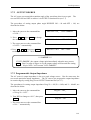
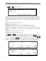
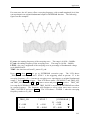
3.6.3 WAVEFORM GENERATOR
The AC source provides the user with two independent sets of waveforms, A and B. Both of
the waveforms include sinusoidal, square, clipped sinusoidal, 30 sets of built-in waveforms,
and 6 sets of user-defined waveforms.
To set waveform A as square wave:
1. Move the cursor to the command of WAVE A.
WAVE A= SINE_
2. Turn RPG to change the option to “SQR”, then
press ENTER .
WAVE A=SQR_
To set waveform B as clipped Sin wave, THD : 10 %
1. Move the cursor to command of WAVE B,
choose “CSIN”.
WAVE B=CSIN_
3-13
PROGRAMMABLE AC SOURCE 61501/61502/61503/61504 User’s Manual
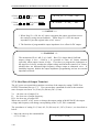
2. Then, LCD display shows the MODE and
PERCENT.
MODE = AMP_
PERCENT = 0.0 %
3. Turn RPG to change the option to “THD”,
press ENTER .
MODE = THD PERCENT = 0.0_ %
4. Press 1 , 0
THD to 10%.
MODE = THD
then press ENTER to set
PERCENT = 10.0 %
*** NOTICE ***
1. The clipped sine is programmed by “AMPlitude” or “Total Harmonic Distortion”.
Programming ranges from 0 to 100% for amplitude (100%: no clipped sine), and
from 0 to 43% for THD (0%: no distortion).
2. User-defined waveform is defined on a remote PC and downloaded from it.
3. For detailed of factory DST waveform refer to Appendix B.
*** WARNING ***
1. When use user-defined waveform, if the waveform frequency is over 1000Hz, it
might cause AC source damage.
2. Because of the bandwidth limitation of AC source, the output may distortion.
Especially when external V reference consists of high frequency composition.
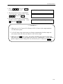
3.6.4 POWER ON STATUS
The AC source allows the user to set the status of the output when power is switched on.
The user can set POWER ON STATUS on CONF functional list (see 3.6). After setting, the
user should save them before powering off (see 3.8.2).
To set the output is on, as 120 Vac, 50Hz, 10Vdc when power-on.
1. Move the cursor to the line of “POWER
ON STATUS : output =”.
POWER ON STATUS : output = OFF_
2. Turn RPG to set output ON, then press
ENTER .
POWER ON STATUS : output = ON
3-14
Local Operation
3. Press 1 , 2 , 0 , ENTER to
set Vac=120.
Vac = 120.0
F=60.0_
Vdc = 0.0
4. Press 5 , 0 , then press ENTER
to set F=50.
Vac = 120.0
F=50.0
Vdc = 0.0
5. Press 1 , 0 , then press ENTER
to set Vdc=10.
Vac = 120.0
F=50.0
Vdc = 10.0
3.6.5 GPIB Address, RS-232C
The AC source offers the mode of remote operation too. The user can set them on CONF
functional list (see 3.6). For detailed please refers to Chapter 7. Prior to remote operation
the user has to set the GPIB address 10 as below:
1. Move the cursor to the command
line of GPIB address.
2. Press
1,
ADDR = 30_
0 , ENTER to set address 10.
ADDR = 10
*** NOTICE ***
Addressing space ranges from 1 to 30.
The AC source offers another remote operation through the RS-232C bus.
protocol is set as follows:
To set parity=ODD, baud rate=19200.
Communication
1. Move the cursor to the command
line of PARITY.
PARITY= NONE_
BAUD=9600
2. Turn RPG to select ODD, then
press ENTER .
PARITY=ODD
BAUD=9600_
PARITY=ODD
BAUD=19200
3. The cursor moves automatically to
the setting position of “BAUD”.
Turn RPG to select "19200", then
press ENTER .
*** NOTICE ***
The options of baud rate are 9600/19200.
/NONE.
The options of parity are EVEN/ODD
3-15
PROGRAMMABLE AC SOURCE 61501/61502/61503/61504 User’s Manual
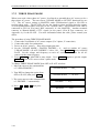
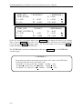
3.7 OUTPUT Functional List
On CHOICE PAGE (see 3.4), press 3 then press ENTER , choose the OUTPUT functional
list.
PAGE CHOICE = 3_
1. SETUP 2.CONF 3.OUTPUT
6. PULSE 7. STEP
5. LIST
10. INTERHAR
4. MANUAL CALI
8. HAR
9. SYN
COUPLE = AC+DC_ DEG ON= 0.0 OFF=IMMED
Prog Zo = OFF
R= 0.00 Ω
L = 0.00 mH
Vs (V/ms) = 0.000
Fs (Hz/ms) = 0.000
DCs (V/ms) = 0.000
T
Press SHIFT , then
to change to next page.
3-PHASE MODE = OFF
DEGREE = 0.0
[ OUTPUT ]
S
T
Press SHIFT , then
to change to next page.
PARALLEL MODE = OFF_
[ OUTPUT ]
Check the AC sources
1. ONLY ONE MASTER
2. SAME RANGE
CHECK OK = NO
S
3-16
Local Operation
3.7.1 COUPLE Mode of Output (AC+DC, AC, DC)
There are three couple mode of AC source output: AC+DC, AC and DC. The user can set
COUPLE on OUTPUT functional list (see 3.7) to fit the application. Then, the display of
MAIN PAGE will change corresponding to the mode.
The procedures of setting from AC+DC to AC are shown as below:
1. Move the cursor to the command of "COUPLE="
COUPLE = AC+DC_
2. Turn RPG to change the option from AC+DC to AC,
then press ENTER .
COUPLE = AC
*** NOTICE ***
The DC mode of AC source is applied to doing some voltage tests. The AC source
has not such many output capacitors, some features like voltage ripple, load transient,
are not as good as DC source. But it can supply positive and negative DC voltage
without changing output connector.
*** WARNING ***
Chroma 61500 AC source have AC/DC/AC+DC output function, at DC output part, it’s still
different from really DC source, the reason as below,
1. The big ripple noise at DC output, it is because of AC source have no output capacitor.
2. The AC source output relay will switch off when the current over the specification, it will
cause output voltage interruption.
P.S. Normally the DC source will change to C.C. mode, then the output voltage slow down
to 0V.
3. Another major reason is, it cannot accept add/increase large capacitor, more than 20uF at
output side directly. It may cause output unstable and damage AC source.
3-17
PROGRAMMABLE AC SOURCE 61501/61502/61503/61504 User’s Manual
For solving above weak point, we suggest that add a special fixture for sure and protection.
61500 AC SOURCE
Fixture Board
Bridge diode
DC input
L
C
Resistor for discharger
+
High frequency
capacitor
Output
SW
SW
_
Illustration for fixture:
1. Bridge diode: Because of internal control circuit of AC source, if users connect more than
20uF capacitor at output side, it may cause output unstable. It’s better to use bridge
diode for isolating external capacitor. Also, it could prevent from wrong connection for
polarity of output DC level. But, it will cause 1.6V drop when adds the bridge diode.
(The user can compensate the output DC voltage by setting voltage level. For example,
the user can program 11.6V in order to get 10 V on the output of fixture board.)
2. L and high frequency capacitor: They can filter high frequency ripple and noise.
not necessary if doesn’t care ripple noise.
But it’s
3. C and SW: It could switch off if UUT part already has capacitor.
4. Discharger resistor and SW: It could discharge the capacitor for avoiding remnant voltage
to hit user when output off. But, users need to consider about power consumption, the
discharger resistor power should be enough for it.
3-18
Local Operation
3.7.2 OUTPUT DEGREE
The AC source can control the transition angle of the waveform when it out or quit. The
user set DEG ON and OFF to achieve it in OUTPUT functional list (see 3.7)
The procedures of setting output phase angle DEGREE ON = 90 and OFF = 180, are
described as below:
1. Move the cursor to the command line
of “ON = ”.
2. Press 9 , 0 , then ENTER to change
the value to " 90.0".
DEG ON = 0.0_
OFF= IMMED
DEG ON = 90.0
OFF= IMMED_
DEG ON = 90.0
OFF= 180.0
3. The cursor moves to the command line
of “OFF= ” automatically.
4. Press 1 , 8 , 0 , then press ENTER
to change the value to " 180.0".
*** NOTICE ***
If "OFF=IMMED", the output voltage quits immediately when the user presses
But if a value of degree is set, the output voltage will last until the setting
degree. Keyin "OFF= 360" become "OFF= IMMED".
QUIT .
3.7.3 Programmable Output Impedance
The AC source’s output impedance is low as a good voltage source. But for some tests, the
user needs particular output impedance. The AC source can program the output impedance
in certain range by setting Prog Zo on OUTPUT functional list (see 3.7).
The procedures for setting output impedance Prog Zo = ON, R = 0.4Ω, and L = 0.8mH, are
described as below:
1. Move the cursor to the command line
of “Prog Zo = OFF ”.
2. Turn RPG to change to “ON ”, then press
ENTER .
Prog Zo = OFF_
Prog Zo = ON
3. The cursor moves to the command line
of “R = ” automatically.
3-19
PROGRAMMABLE AC SOURCE 61501/61502/61503/61504 User’s Manual
4. Press 0 , . , 4 , then press ENTER
to change R to " 0.4Ω".
5. Press 0 , . , 8 , then press ENTER
to change L to " 0.8 mH".
R = 0.4_ Ω
R = 0.40 Ω
L = 0.00
L = 0.8_
mH
mH
*** NOTICE ***
1. When Prog Zo = ON, the AC source reprogram the output waveform to meet
the setting by using current feedback. When Prog Zo = OFF, the output
impedance is just the original value of AC source.
2. The function of programmable output impedance is no effect for DC output.
*** WARNING ***
The maximum of R is 1.0Ω, L is 1.0 mH. But if L is larger than 0.5mH and
output voltage is low ( <100Vac ), it’s possible to cause AC Source unstable
especially when output current is large. Users have to program the inductance to
the target level slowly, monitor the output voltage and listen the sound of AC Source
whether there are abnormal high frequency voltage output or abnormal voice. If
instability happens, disable the output impedance programming and use an external
impedance network.
3.7.4 Slew Rate of Output Transient
The AC source can control the transition waveform of the output by setting COUPLE on
OUTPUT functional list (see 3.7). User can set three commands to achieve the transient
state of output waveform: Vs (V/ms), Fs (Hz/ms), DCs (V/ms).
Vs : the slew rate of output Vac.
Fs : the slew rate of output frequency.
DCs : the slew rate of output Vdc.
When user run OUT of AC source or change the output setting in MAIN PAGE, the output
voltage and frequency will change corresponding to the Vs, Fs, DCs commands.
The procedures of setting Vs (V/ms)=0.2, Fs (Hz/ ms)=0.1, DCs (V/ms)=1, are described as
below :
1. Move the cursor to the command line
of “Vs (V/ms) = ”.
3-20
Vs (V/ms) = 0.000_
Local Operation
2. Press 0 , . , 2 , then press ENTER
to change the value to “0.2”.
Vs (V/ms) = 0.200
3. The cursor moves to the command line
of “Fs (Hz/ms)=” automatically. Press
0 , . , 1 , then press ENTER .
4. The cursor moves to the command line
of “DCs (V/ms)=” automatically. Press
1 , then press ENTER .
Fs (Hz/ms) = 0.100
DCs (V/ms) = 1.000_
*** NOTICE ***
1. When user set Vs (V/ms)=0, Fs (Hz/ms)=0, DCs (V/ms)=0, the output transient
is in the fastest speed.
2. Vs, Fs DCs have large input range in software programming, but the output can
not exactly follow the slew rate when Vs, DCs are too large.
3. When user run OUT of AC source, the output will follow the setting to final state.
But when user run QUIT, the output will vary to 0 V immediately. If user want to
quit the output with the setting slew rate, he must keyin 0 V then press ENTER .
3-21
PROGRAMMABLE AC SOURCE 61501/61502/61503/61504 User’s Manual
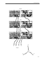
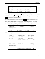
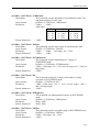
3.7.5 THREE PHASE MODE
When users need a three-phase AC power, it's allowed to assemble three AC sources to be a
three-phase AC power. The user can set 3-PHASE MODE on OUTPUT functional list (see
3.7). The AC source setting as MASTER sends SYNchronized signal to SLAVEs to
position phase angle. The SLAVEs also use the signal to trigger and shut down the output.
To send synchronized signal, users have to use a special cable. One terminal of the cable is
connected to SYN (in rear panel, BNC connector), it’s the MASTER. Another terminals
connects to /Remote-Inhibit of TTL signal (in rear panel, 9-Pin D-Type connector, see
Appendix A), it’s the SLAVE. For more information about the cable, please consult your
dealer.
The procedure of using THREE PHASE MODE:
1. Connect the N terminals of AC source outputs. (For 3-phase, Y connection).
2. Connect the cable for synchronism.
3. Power on all AC sources. Keep all in output quit state.
4. Set the 3-PHASE MODE = MATER, DEGREE = 0. And set another AC source
3-PHASE MODE = SLAVE, DEGREE = 240 or 120. Press PAGE/EXIT twice to MAIN
PAGE. Set the voltage and frequency on each AC source. It is better for all AC
sources set the same frequency.
5. Press OUT/QUIT at MASTER to start output. Press OUT/QUIT again to quit the output.
OUT/QUIT of SLAVE is no use when 3-phase mode.
To change THREE PHASE MODE from OFF to SLAVE as below:
1. Move the cursor to the command line
of “3-PHASE MODE=”.
3-PHASE MODE = OFF_
2. Turn RPG to change the option from
OFF to SLAVE, then press ENTER .
3-PHASE MODE =
SLAVE
3. The cursor moves to the command line
of “ DEGREE =” automatically.
DEGREE
4. Press 1 , 2 , 0 , then press
ENTER .
DEGREE = 120.0
3-22
=
0.0_
Local Operation
Master
Slave
Slave
L1
N
L3
L2
L1
Output
N
L2
L3
3-23
PROGRAMMABLE AC SOURCE 61501/61502/61503/61504 User’s Manual
1.
*** NOTICE ***
The DEGREE of MASTER is 0, and the DEGREE of SLAVE is 120,
it means the SLAVE is 120 degree lead of MASTER.
2. The first cycle of SLAVE waveform will be distorted if the DEG ON
(output on degree, see 3.7.2) doesn’t be set correctly. For example,
if the MASTER DEG ON = 90, the DEG ON of SLAVE must be 210
(120 + 90 = 210). Another SLAVE must DEG ON = 330 (240 + 90 =
330).
*** NOTICE ***
1. If the DEG OFF (quit degree, see 3.7.2) of MASTER and SLAVE are
IMMED, the MASTER phase angle will quit on zero degree, and the SLAVE
will quit on 120 or 240 degree. But if users assign quit degree, for
example, if the MASTER DEG OFF = 90, the DEG OFF of SLAVE must
be 210 (120 + 90 = 210). Another SLAVE must DEG OFF = 330 (240 +
90 = 330).
2. The voltage setting of 3-phase output is line-to-neutral VLN for each phase.
If users need the line-to-line voltage VLL, the VLN must equal to VLL / 1.732.
*** NOTICE ***
The user can use two units of 61500 AC source to connect in series to get higher
voltage by three-phase mode.
The phase degree should be set on 180 degree.
And the user also need to set the right DEG ON and OFF to get right phase when
output is ON or OFF.
*** WARNING ***
1. Only one AC source can be set to MASTER, or it may cause damage when
run 3-PHASE MODE.
2. Users can not connect L terminals of AC source outputs together, even set the
DEGREE = 0 of SLAVE.
3. For safety concern, the 3-phase mode can’t save to power-on status.
3-24
Local Operation
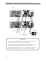
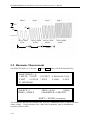
3.7.6 PARALLEL MODE
When the power of one AC source is not enough to drive load, it's allowed to parallel AC
sources if they are the same model. The user can set PARALLEL MODE on OUTPUT
functional list (see 3.7). The AC source setting as MASTER sends SCLK and PWM signals
to SLAVE one. Users program output only in MASTER, and read the measurement
individually.
The procedures of paralleling AC source:
1. Quit the output of AC sources, set Vout = 0V. Set all to the same RANGE and status of
OUTPUT RELAY.
2. Connect SCLK signal (in rear panel, BNC connector) together. Connect PWM signal
together, too. Connect the same cable used in 3.7.5 Three Phase Mode.
3. Connect the terminals of AC source outputs (N to N, L to L), then, connect to the load.
4. Set the AC source as MASTER first, set the SLAVE finally. After setting, press
PAGE/EXIT twice to MAIN PAGE.
5. The other settings of AC source cannot be changed when it is in parallel mode.
6. The MASTER can program and run or quit the output, the SLAVE only measures the
output of itself.
The procedure of removing PARALLEL MODE:
1. Quit the output of AC source from MASTER. Set Vout = 0V.
2. Don't change the PARALLEL MODE to OFF, power off the MASTER and SLAVE at the
same time. (Suggestion: Keep all power switch on, assemble an additional power switch to
control the power line input.)
To change parallel mode OFF to MASTER as below:
1. Move the cursor to the command line
of “PARALLEL MODE=”.
2. Turn RPG to change the option from
OFF to MASTER, then press ENTER .
After checking PARALLEL MODE
setting and RANGE setting, confirm it.
3. The cursor moves to the command line
of “ CHECK OK” automatically.
4. Turn RPG to change the option from
NO to YES, then press ENTER .
PARALLEL MODE = OFF_
PARALLEL MODE = MASTER
CHECK
OK
=
CHECK OK =
NO_
YES
3-25
PROGRAMMABLE AC SOURCE 61501/61502/61503/61504 User’s Manual
Master
Slave
PWM and SCLK
cable
Output
N
Input Power
L
Synchronizing cable
Power Switch
*** WARNING ***
1. If there is not only one MASTER, or AC sources' RANGE is not the same, it
may cause damage of AC source when run parallel mode.
2. In parallel mode, the output power has not to exceed 90% of total power, in
order to avoid damage caused by unbalance outputs of AC sources.
3. The procedure to turn off the AC sources is very important. Power off the
MASTER and SLAVE at the same time. Or the unit may be damaged.
3-26
Local Operation
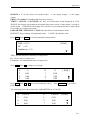
3.8 Save and Recall
The AC source offers two modes for the user to save and recall output setting or system data.
They are described in 3.8.1 and 3.8.2.
3.8.1 Save and Recall Output Setting
The AC source offers nine channels for the user to save a set of frequently used Vac, F, Vdc,
and to recall them for later use. For example, in the MAIN PAGE (see 3.3), keyin the output
settings as below and save the settings to memory channel 5.
Vac = 230.0
V = 0.00
P = 0.0
F
= 50.00
F = 0.00
PF = 0.000
Press SHIFT , then PAGE/EXIT , to run the SAVE function.
Vdc = 10.0_
H
I = 0.00
CF = 0.00
S
T
The display will show as below:
CHOICE 1 - 9 , PRESS (ENTER) TO SAVE MAIN PAGE
F = 60.00
Vdc = 0.0
1. Vac = 0.0
2. Vac = 120.0
F = 60.00
Vdc = 0.0
3. Vac = 0.0
F = 60.00
Vdc = 0.0
T
The cursor stays in channel 1. The user can press 1 - 9 to select channel or use
, , or press SHIFT then
to change page to the destination. The cursor stays in
channel 5 after pressing 5 .
CHOICE 1 - 9 , PRESS (ENTER) TO SAVE MAIN PAGE
4. Vac = 0.0
F = 60.00
Vdc = 0.0
F = 60.00
Vdc = 0.0
5. Vac = 0.0
S
6. Vac = 0.0
F = 60.00
Vdc = 0.0
T
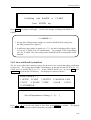
Press ENTER to save the output settings to channel 5. The display will show saving status
for about 3 seconds. The display is shown as below.
Saving now, do not shut down ........
3-27
PROGRAMMABLE AC SOURCE 61501/61502/61503/61504 User’s Manual
Then output setting in MAIN PAGE show in channel 5.
The display is shown as below.
CHOICE 1 - 9, PRESS (ENTER) TO SAVE MAIN PAGE
4. Vac = 0.0
F = 60.00
Vdc = 0.0
F = 50.00
Vdc = 10.0
5. Vac = 230.0
S
6. Vac = 0.0
F = 60.00
Vdc = 0.0
T
Then, press PAGE/EXIT to return to MAIN PAGE.
Recalling from memory channel to MAIN PAGE is shown the following : In MAIN PAGE,
press SHIFT then / - to run the RECALL function. The display is shown as below :
CHOICE 1 - 9 , PRESS (ENTER) TO RECALL
F = 60.00
Vdc = 0.0
1. Vac = 0.0
2. Vac = 120.0
F = 60.00
Vdc = 0.0
3. Vac = 0.0
F = 60.00
Vdc = 0.0
T
The cursor stays in channel 1. The user can press 1 - 9 to select channel or use
, , or press SHIFT then to change page to the destination. The cursor stays in
channel 2 after pressing 2 . The display is shown as below.
CHOICE 1 - 9 , PRESS (ENTER) TO RECALL
1. Vac = 0.0
F = 60.00
Vdc = 0.0
F = 60.00
Vdc = 0.0
2. Vac = 120.0
3. Vac = 0.0
F = 60.00
Vdc = 0.0
T
Press ENTER , the display returns to MAIN PAGE automatically. And the output settings are
Vac = 120, F = 60, Vdc = 0, just as the settings saved in memory channel 2.
Vac = 120.0_
V = 0.00
P = 0.0
F
= 60.00
Vdc = 0.00
H
F = 0.00
PF = 0.000
I = 0.00
CF = 0.00
S
T
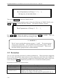
If the recalling settings are output of RANGE or over the V LIMIT (see 3.5.2, 3.5.3), the
display will show the following:
3-28
Local Operation
Conflicting with RANGE or
Press
Press ENTER to return to recall page.
V LIMIT
ENTER key
Check if the settings violating the RANGE or V
LIMIT.
*** NOTICE ***
1. Saving and recalling output settings are acted for MAIN PAGE setting only,
the other parameters are ignored.
2. In different couple mode of output (see 3.7.1), the lack of settings will be regular
to Vac=0V, F=60Hz, Vdc=0V automatically. For example, in DC output mode,
Vac=0V, F=60Hz, Vdc is the setting value in MAIN PAGE as running the SAVE
function.
3.8.2 Save and Recall System Data
The AC source offers three memory groups for the user to save system data and to recall them
for later use. The system data includes all parameters in function list like SETUP (see 3.5),
CONF (see 3.6) and OUTPUT (see 3.7). In the CHOICE PAGE (see 3.4), press SHIFT , then
PAGE/EXIT, to run the SAVE function. The displays are shown as below.
PAGE CHOICE = 1_
1. SETUP 2.CONF 3.OUTPUT
6. PULSE 7. STEP
5. LIST
10. INTERHAR
4. MANUAL CALI
8. HAR
9. SYN
Save all parameters to Group ( 1 - 3 ) :
1_
Press 1 - 3 to choose one group to save, then press ENTER to confirm.
will show the saving status sentence about three seconds as below.
The display
3-29
PROGRAMMABLE AC SOURCE 61501/61502/61503/61504 User’s Manual
Save all parameters to Group ( 1 - 3 ) : 1_
Saving now, do not shut down ........
Then, press PAGE/EXIT to return to CHOICE PAGE.
Recalling system data from memory group is shown the following: In CHOICE PAGE, press
SHIFT then
/ - to run the RECALL function. The display will show as below:
Recall parameters of Group ( 1 - 3 ) :
1_
Press 1 - 3 to choose one group to recall, then press ENTER to confirm.
display will return to CHOICE PAGE after loading the data.
Then, the
*** NOTICE ***
The AC source provides three memory groups: 1, 2, and 3. The memory group
1 keeps power-on defaults. The setup data saved into memory group 1 will be
recalled automatically when the AC source is powered on again. Those saved
into other memory groups must be recalled manually.
3.9 Protection
The AC source provides protection for software and hardware. When protection is happened,
the AC source will quit the output and turn off the output relays, then show the condition of
protection in display. If any protection is triggered to hold normal output, please remove the
errors, then press ENTER to unlock the protection so as to resume the normal operation.
Protection for software are listed as below:
Protection
OVER CURRENT
OVER POWER
OUTPUT OVP
3-30
Description
When output current is over the I limit or the current specification.
When output power is over the specification.
1. It is feedback open protection, and means that the feedback loop is
broken or the output voltage goes wrong.
2. When the out voltage is over the limit of each RANGE. See 3.3.
Local Operation
Protection for hardware are listed as below:
Protection
FAN FAIL
INT - AD
INT - DD
OUTPUT SHORT
INPUT FAIL
OVER TEMP
Description
It is fan failure protection, and means that the cooling fan
malfunctions.
It is inner AD power stage (see 6.2) protection, and means that the
output voltage is over or under the specific value.
It is inner DD power stage (see 6.2) protection, and means that the
output voltage is over or under the specific value.
It is short protection, and means that the output terminals are shorted.
It is power failure protection, and means that the line input voltage is
lower or higher than specification.
It is over temperature protection, and will be enabled when the
internal temperature of the AC source is too high.
3-31
Calibration
4. Calibration
4.1 Introduction
The ac source built a simple way to calibrate the output and measurement accuracy without
opening cover. Users can do it just follow the procedures step by step. A voltage meter,
current meter, suitable load and +5V dc source are needed for while calibration procedure.
Connections for these instruments please refer to Figure 4.1.1. There are three items need to
calibrate. But it is not necessary to calibrate all at once. User can just choose one item if
needs.
Current
Meter
+5V DC
Source
Load
L N
+
AC source
-+Voltage
Meter
Figure 4.1.1
4.2 MANUAL CALI Functional List
Users can choose " 4. MANUAL CALI " in CHOICE PAGE to enter the calibration
procedure. Before showing the calibration items, for safety reason, user must enter
password. The password is shown in this manual, in order to confirm the user read the
manual before doing the calibration procedure.
4-1
PROGRAMMABLE AC SOURCE 61501/61502/61503/61504 User’s Manual
PAGE CHOICE = 4_
1. SETUP 2.CONF 3.OUTPUT
6. PULSE 7. STEP
5. LIST
10. INTERHAR
4. MANUAL CALI
8. HAR
9. SYN
Enter Password : _
( You can get password in user's manual ! )
Enter Password : * * * *
( You can get password in user's manual ! )
*** NOTICE ***
1. The Password of entering calibration procedure is " 7377 ", then press ENTER .
2. Before calibrating the AC source, users should read the procedure in details.
Or it may lose some data in memory because of improper operation.
The display changes to CALIBRATION CHOICE PAGE as below after keying the right
password.
CALIBRATION CHOICE = 1_
1. V OUT AND MEAS.
2. I MEAS.
3. EXT Vref.
V OUT AND MEAS. : output voltage and voltage measurement accuracy calibration.
I MEAS. : current measurement accuracy calibration.
EXT Vref. : external Vref calibration.
4-2
Calibration
4.2.1 Output Voltage and Voltage Measurement Calibration
Users can enter CALIBRATION CHOICE page after pressing password, see 4.2.
press 1 , ENTER , to do the output voltage and voltage measurement calibration.
Then,
CALIBRATION CHOICE = 1
1. V OUT AND MEAS.
2. I MEAS.
3. EXT V.
Fig 3.8.1.1
Please Remove Load Before Calibrating
Press <ENTER> to start
1. V OUT AND MEAS. ACCURACY CALI
A. KEYIN THE MEASURED Vdc
Vdc offset = _
mV
150V RNG
T
In this step A of V OUT AND MEAS. ACCURACY CALI, the user should keyin the AC
source's DC output voltage measured by digital voltage meter (DVM) in mV. Then, monitor
the reading of DVM, keyin the DC output voltage repeatedly until DC output is less than ±10
mV.
*** NOTICE ***
1.The Vdc offset may be positive or negative. The positive of DVM connect to the
line of AC source output, and the negative of DVM connect to the Neutral of
AC source output. See Fig. 4.1.1.
2.The load must be off at all steps of V OUT AND MEAS. ACCURACY CALI.
Then press SHIFT , then
to change to next step.
1. V OUT AND MEAS. ACCURACY CALI 150V RNG
B. WAIT TWO SECONDS THEN ( ENTER )
S
T
Vac = 0.00 V
Vdc = 0.00 V
4-3
PROGRAMMABLE AC SOURCE 61501/61502/61503/61504 User’s Manual
In this step B of V OUT AND MEAS. ACCURACY CALI., the display shows the offset of
Vac and Vdc measured by AC source. They are produced by internal components. Wait two
seconds then press ENTER , then Vac = 0.00, Vdc = 0.00 .
*** NOTICE ***
The AC source calibration steps are allowed to do individually, but it is better to
follow the calibration procedure step by step (step A, step B ...). Or it may cause
output and measurement errors.
Then press SHIFT , then
to change to next step.
1. V OUT AND MEAS. ACCURACY CALI
150V RNG
C. ( ENTER ) THEN CHECK OUTPUT IS 15VAC
D. ( ENTER ) THEN KEYIN DVM MEAS. 150VAC S
T
0.00_
V
In above step C of V OUT AND MEAS. ACCURACY CALI., the user should not turn on the
load. Press ENTER , then check the output voltage measured by DVM is about 15VAC.
This step is just to make sure the connection is correctly.
Then go to next step D. Press ENTER , check the output voltage measured by DVM is about
150VAC. Keyin the exact value measured by DVM, then press ENTER .
Then press SHIFT , then
to change to next step.
1. V OUT AND MEAS. ACCURACY CALI
300V RNG
E. ( ENTER ) THEN CHECK OUTPUT IS 30VAC
F. ( ENTER ) THEN KEYIN DVM MEAS. 300VAC
0.00_ V
S
In above step E of V OUT AND MEAS. ACCURACY CALI., the user should not turn on the
load. Press ENTER , then check the output voltage measured by DVM is about 30VAC.
This step is just to make sure the connection is correctly.
Then go to next step F. Press ENTER , check the output voltage measured by DVM is about
300VAC. Keyin the exact value measured by DVM, then press ENTER .
Step F is the final step of V OUT AND MEAS. ACCURACY CALI. Press PAGE/EXIT to
exit that page. Then display will show as below. Press ENTER to save the calibration
results.
4-4
Calibration
Press ( ENTER ) to save .
Press ( PAGE/EXIT ) not to save .
*** NOTICE ***
1. Users can press PAGE/EXIT to exit to the calibration choice page at every step.
2. See the above display, if press PAGE/EXIT not to save the result, the result of
calibration still works, until turn the power off.
4.2.2 Current Measurement Calibration
Users can enter CALIBRATION CHOICE page after pressing password, see 4.2.
press 2 , ENTER , to do the current measurement calibration.
CALIBRATION CHOICE =
1. V OUT AND MEAS.
3. EXT Vref.
Then,
2
2. I MEAS.
Fig 3.8.1.1
1. CURRENT MEAS. ACCURACY CALI 150V RNG
A. WAIT TWO SECONDS THEN ( ENTER )
Iac = 0.00 A
Idc = 0.00 A
T
In above step A of CURRENT MEAS. ACCURACY CALI., the display shows the offset of
Iac and Idc measured by AC source. They are produced by internal components. Wait
seconds then press ENTER , then Iac = 0.00A, Idc = 0.00A .
4-5
PROGRAMMABLE AC SOURCE 61501/61502/61503/61504 User’s Manual
Then press SHIFT , then
to change to next step.
1. CURRENT MEAS. ACCURACY CALI 150V RNG
B. ( ENTER ) THEN CHECK CURRENT IS 1.6A
C. ( ENTER ) THEN KEYIN CURRENT MEAS. 16A
0.00 A
S
In above step B of CURRENT MEAS. ACCURACY CALI., press ENTER then AC source
will output 12.5VAC. The user should apply suitable load to output, to make the output
current measured by current meter ( or power analyzer ) be about 1.6A (for 61504). The
different model shows different current value in display. If the output current is ok after
applying load, press ENTER , then AC source will output 125VAC. The output current will
be 10 times of step B, 16A. Keyin the exact value of current measured by current meter.
The output current of step B. and step C. are shown as below :
Model
Step B.
Step C.
61501 (500 VA)
0.4 A
4A
61502 (1000 VA)
0.8 A
8A
61503 (1500 VA)
1.2 A
12 A
61504 (2000 VA)
1.6 A
16 A
Step C is the final step of CURRENT MEAS. ACCURACY CALI. Press PAGE/EXIT to exit
that page. Then display will show as below. Press ENTER to save the calibration result.
Press ( ENTER ) to save .
Press ( PAGE/EXIT ) not to save .
*** NOTICE ***
1. The resistance of applied load must be constant, so that the load current is
proportional to output voltage. If not, the step B of CURRENT MEAS.
ACCURACY is insignificant. Users only need to meet the current of step C
when output voltage is 125VAC.
2. When doing the procedure of calibration, the protection is removed temporarily.
It may cause damage of AC source if applying unsuitable load.
4-6
Calibration
4.2.3 External Vref Calibration
Users can enter CALIBRATION CHOICE page after pressing password (see 4.2). Then,
press 3 , ENTER , to do the external Vref calibration. See detailed as below. It is not
necessary to do this item if no option board ( GPIB, RS-232 and Vref board ) is installed.
CALIBRATION CHOICE = 3
1. V OUT AND MEAS.
2. I MEAS.
3. EXT Vref.
Fig 3.8.1.1
Please Remove Load Before Calibrating
Press <ENTER> to start
3. EXTERNAL Vref CALI
150V RANGE
A. Verf INPUT SHORT
WAIT TWO SECONDS THEN ( ENTER )
Vdc = 0.00 V
T
In above step A of EXTERNAL Vref CALI., short the external Vref input terminal to make
input is 0V, then the display shows the measured Vdc from AC source. They are offset
voltages produced by internal components. Wait two seconds then press ENTER , then Vdc =
0V.
Then press SHIFT , then
to change to next step.
3. EXTERNAL Vref CALI
150V RANGE
B. INPUT EXT. V 5VDC - WAIT TWO SECOND
KEYIN EXT. V DVM MEAS.
( ENTER ) S
0.000
VDC
In above step B of EXTERNAL Vref CALI., the user apply +5Vdc to Vref BNC connector
from outer DC source. Check the output voltage of AC source is about 106Vdc, then keyin
the exact value of input Vref voltage (not AC source output) measured from DVM.
4-7
PROGRAMMABLE AC SOURCE 61501/61502/61503/61504 User’s Manual
Step B is the final step of EXTERNAL Vref CALI. Press PAGE/EXIT to exit that page.
Then display will show as below. Press ENTER to save the calibration result.
Press ( ENTER ) to save .
Press ( PAGE/EXIT ) not to save .
4-8
Application
5. Application
5.1 General
Not only programming the steady sine output voltage and frequency, the AC source model
61501/61502/61503/61504 provide several powerful functions to simulate all kinds of power
line disturbance. Users can make the output change through a number of value in LIST
mode (see 5.2), or make the output change to its set value for a specific period of time in
PULSE mode (see 5.3), even make the output change to its set value step by step in STEP
mode (see 5.4). With these functions, it is easy to simulate such as cycle dropout, transient
spike, brown out, etc.
Not only measurements related to power in MAIN PAGE (see 3.3), the AC source model
61501/61502/61503/61504 also provide harmonic measurement up to 40 orders (see 5.5).
For modern power testing, the AC source allows users to compose different harmonic
components to synthesize harmonic distorted wave-shapes (see 5.6). The AC source also
can achieve interharmonics waveform, a sweeping frequency superimposed on a static
fundamental wave (see 5.7).
5.2 List Mode
On CHOICE PAGE (see 3.4), press 5 then ENTER , choose the LIST functional list.
PAGE CHOICE = 5_
1. SETUP 2.CONF 3.OUTPUT
6. PULSE 7. STEP
5. LIST
10. INTERHAR
COUNT = 0
TRIG = AUTO
BASE = TIME
4. MANUAL CALI
8. HAR
9. SYN
[ LIST ]
<SHIFT> <ENTER> to Execute
T
The waveform programming of LIST mode is the assembly of the SEQuences. The output
waveform will start from SEQ=0, then SEQ by SEQ. The execution will stop until a SEQ
which TIME or CYCLE = 0, even the following SEQs have been set will not be executed.
COUNT : the whole sequences’ executing number of times. COUNT = 0 : infinity.
TRIG = AUTO / MANUAL : the way to trigger. AUTO : it will finish all COUNT number
when trigger. MANUAL : it will execute sequence waveform for only once. It has the
5-1
PROGRAMMABLE AC SOURCE 61501/61502/61503/61504 User’s Manual
same result in COUNT=1.
BASE = TIME / CYCLE: the unit of sequence length.
Press SHIFT , then
to change to next page for sequence programming.
SEQ = 0
Vs = 0.0
Ve = 0.0
WAVE = A
DEGREE = 0.0
Fs = 60.00
Fe = 60.00
TIME = 0.0
[ LIST ]
DCs = 0.0
DCe = 0.0
ms
SEQ : the number of sequence. All sequences must start by zero.
SEQ is 99.
DEGREE : the phase angle when the sequence starts.
Vs, Fs, DCs : the initial waveform when the sequence starts.
Ve, Fe, DCe : the final waveform when the sequence ends.
WAVE = A / B : to choose waveform ( see 3.6.3 ).
TIME / CYCLE : the length of sequence.
S
T
The maximal number of
After setting sequences, press PAGE/EXIT to exit to LIST mode page. Press SHIFT , then
ENTER to change to execution page. The LCD shows _TRIG_ON is under action, and *
STOP * is the triggering status at present. Press ENTER to trigger. Then LCD shows status
* RUNNING * and TRIG_OFF waiting for user to stop the LIST waveform output. The
LCD will shows * STOP * when the AC source executed all sequences and COUNT.
_TRIG_ON
V = 0.00
P = 0.0
_TRIG_OFF
V = 0.00
P = 0.0
* STOP *
F = 0.00
PF = 0.000
[ LIST ]
I = 0.00
CF = 0.00
* RUNNING *
F = 0.00
PF = 0.000
S
T
[ LIST ]
I = 0.00
CF = 0.00
S
T
If the AC Source is in running status, press OUT/QUIT , the output will quit waveform to zero
voltage. Then, if press OUT/QUIT again, the AC source only out the waveform set in MAIN
PAGE. Users must press ENTER to trigger again. Or if in quit status, users can press
ENTER to output LIST waveform directly.
The programmed LIST mode waveform will shut down when press PAGE/EXIT to exit LIST
execution page.
5-2
Application
LIST mode example:
COUNT = 1
TRIG = AUTO
BASE = TIME
[ LIST ]
T
<SHIFT> <ENTER> to Execute
SEQ = 0
Vs = 20.0
Ve = 80.0
WAVE = A
DEGREE = 90.0
[ LIST ]
Fs = 50.00
DCs = 0.0
Fe = 50.00
DCe = 0.0
S
TIME = 75.0
ms
T
SEQ = 1
Vs = 20.0
Ve = 20.0
WAVE = A
DEGREE = 0.0
Fs = 50.00
Fe = 50.00
TIME = 80.0
DCs = 0.0
DCe = 100.0
ms
SEQ = 2
Vs = 20.0
Ve = 100.0
WAVE = A
DEGREE = 0.0
Fs = 50.00
Fe = 400.00
TIME = 100.0
[ LIST ]
DCs = 0.0
DCe = 0.0
S
ms
T
[ LIST ]
S
T
5-3
PROGRAMMABLE AC SOURCE 61501/61502/61503/61504 User’s Manual
The output waveform :
SEQ 1
SEQ 0
SEQ 2
90°
50V
75ms
80ms
100ms
5.3 Pulse Mode
On CHOICE PAGE (see 3.4), press 6 then ENTER , choose the PULSE functional list.
PAGE CHOICE = 6_
1. SETUP 2.CONF 3.OUTPUT
6. PULSE 7. STEP
5. LIST
10. INTERHAR
COUNT = 0
Vac = 0.0
DUTY = 0.0
Press SHIFT , then
5-4
4. MANUAL CALI
8. HAR
9. SYN
[ PULSE ]
F = 60.00
Vdc = 0.0
%
PERIOD = 0.0
ms
<SHIFT> <ENTER> to Execute
T
to change to next page.
Application
TRIG = AUTO
DEGREE = 0.0
WAVE = A
[ PULSE ]
<SHIFT> <ENTER> to Execute
S
The PULSE mode allows users to program a particular waveform attach to normal output set
in MAIN PAGE. The waveform programming is to specify duty percent on top of
programmed output, and the transient state.
COUNT: the repeat number of pulse.
Vac, F, Vdc: the Vac, F and DC output in the duty of period.
DUTY: the proportion of pulse in one period.
PERIOD: the length of a pulse period.
TRIG = AUTO / MANUAL : the way to trigger. AUTO : it will finish all COUNT number
when trigger. MANUAL : it will execute pulse waveform for only once. It has the same
result in COUNT=1.
WAVE = A / B: to choose waveform ( see 3.6.3 ).
DEGREE: the output phase angle of pulse.
Press SHIFT , then ENTER to go to PULSE execution page. The LCD shows _TRIG_ON is
under action, and * STOP * is the triggering status at present. Press ENTER to trigger.
Then LCD shows status * RUNNING * and TRIG_OFF waiting for user to stop the PULSE
waveform output. The LCD shows * STOP * when the AC source executed all COUNT
number.
_TRIG_ON
* STOP *
V = 0.00
P = 0.0
F = 0.00
PF = 0.000
_TRIG_OFF
* RUNNING *
V = 0.00
P = 0.0
F = 0.00
PF = 0.000
[ PULSE ]
I = 0.00
CF = 0.00
S
T
[ PULSE ]
I = 0.00
CF = 0.00
S
T
If the AC Source is in output status, press OUT/QUIT , the output will quit waveform to zero
voltage. Then, if press OUT/QUIT again, the AC Source only out the waveform set in MAIN
PAGE. Users must press ENTER to trigger again. Or if in quit status, users can press
5-5
PROGRAMMABLE AC SOURCE 61501/61502/61503/61504 User’s Manual
ENTER to output PULSE waveform directly.
The pulse wave will shut down when press PAGE/EXIT to exit PULSE execution page.
PULSE mode example:
In MAIN PAGE:
Vac = 50.0
V = 0.00
P = 0.0
F
= 50.00
Vdc = 0.0
L
F = 0.00
PF = 0.000
I = 0.00
CF = 0.00
S
T
In PULSE setting page:
COUNT = 3
Vac = 100.0
DUTY = 35.0
TRIG = AUTO
DEGREE = 90.0
[ PULSE ]
F = 50.00
Vdc = 0.0
% PERIOD = 100.0
ms
<SHIFT> <ENTER> to Execute
T
WAVE = A
[ PULSE ]
<SHIFT> <ENTER> to Execute
5-6
S
Application
The output waveform:
Pulse 1
Pulse 2
Pulse 3
100Vac
90°
50Vac
50V
35ms
65ms
100ms
5.4 Step Mode
On CHOICE PAGE ( see 3.4 ), press 7 then ENTER , choose the STEP functional list.
PAGE CHOICE = 7_
1. SETUP 2.CONF 3.OUTPUT
6. PULSE 7. STEP
5. LIST
10. INTERHAR
COUNT = 0
Vac = 0.0
dV = 0.0
4. MANUAL CALI
8. HAR
9. SYN
DWELL = 0.0
ms [ STEP ]
F = 60.00
Vdc = 0.0
dF = 0.00
dDC = 0.0
<SHIFT><ENTER> to Execute
T
5-7
PROGRAMMABLE AC SOURCE 61501/61502/61503/61504 User’s Manual
Press SHIFT , then
to change to next page.
TRIG = AUTO
DEGREE = 0.0
WAVE = A
[ STEP ]
<SHIFT><ENTER> to Execute
S
The STEP mode offers a easy and automatic-change function to change output waveform in
a regular level and time. But the variation between two steps changes rapidly, not gradually.
The waveform programming is to set an initial waveform, specify the dwell time and change
of every step, and the number of change step. After execution, the output wave will keep on
last step.
COUNT : the number of each change execute.
DWELL : the length of each step.
Vac, F, Vdc : the initial value of Vac, F, DC when STEP mode starts to execute.
dV, dF, dDC : the difference value of each step. ( The negative value is allowed. )
TRIG = AUTO / MANUAL : the way to trigger. AUTO : it will finish all COUNT number
when trigger. MANUAL : the output waveform will change just one step for each
execution.
WAVE = A / B : to choose waveform ( see 3.6.3 ).
DEGREE : the output phase angle of each step.
Press SHIFT , then ENTER to go to STEP execution page. The LCD shows _TRIG_ON is
under action, and * STOP * is the triggering status at present. Press ENTER to trigger.
Then LCD shows status * RUNNING * and TRIG_OFF and TRIG_PAUSE. Press
or
to move cursor and press ENTER to select. TRIG_OFF is to stop the STEP waveform
changing. TRIG_PAUSE is to keep the STEP waveform until TRIG_CONTINUE is
selected. The LCD will shows * STOP * when the AC source executed all COUNT number.
_TRIG_ON
V = 0.00
P = 0.0
* STOP *
F = 0.00
PF = 0.000
[ STEP ]
I = 0.00
CF = 0.00
_TRIG_OFF
* RUNNING *
TRIG_PAUSE
V = 0.00
F = 0.00
I = 0.00
PF = 0.000
CF = 0.00
P = 0.0
5-8
S
T
[ STEP ]
S
T
Application
_TRIG_CONTINUE
V = 0.00
P = 0.0
* PAUSE *
F = 0.00
PF = 0.000
[ STEP ]
S
T
I = 0.00
CF = 0.00
If the AC Source is in output status, press OUT/QUIT , the output will quit waveform to zero
voltage. Then, if press OUT/QUIT again, the AC Source only out the waveform set in MAIN
PAGE. Users must press ENTER to trigger again. Or if in quit status, users can press
ENTER to output STEP waveform directly.
The STEP wave will stop to execute when press PAGE/EXIT to exit STEP execution page.
When TRIG = MANUAL, the LCD shows TRIG_UP and TRIG_DOWN. The output
waveform is changed to the next step if TRIG_UP is selected. The output waveform is
changed back to last step if TRIG_DOWN is selected.
_TRIG_UP
TRIG_DOWN
V = 0.00
P = 0.0
* STOP *
F = 0.00
PF = 0.000
[ STEP ]
S
T
I = 0.00
CF = 0.00
STEP mode example:
COUNT = 3
Vac = 40.0
dV = 10.0
TRIG = AUTO
DEGREE = 90.0
DWELL = 60.0
ms [ STEP ]
F = 50.00
Vdc = 0.0
dF = 50.00
dDC = 20.0
<SHIFT><ENTER> to Execute
T
WAVE = A
[ STEP ]
<SHIFT><ENTER> to Execute
S
5-9
PROGRAMMABLE AC SOURCE 61501/61502/61503/61504 User’s Manual
Initial
Step 1
Step 2
Step 3
50V
90°
90°
40Vac 50Hz
0Vdc
60ms
50Vac 100Hz
20Vdc
60Vac 150Hz
40Vdc
60ms
60ms
70Vac 200Hz
60Vdc
5.5 Harmonic Measurement
On CHOICE PAGE (see 3.4), press 8 then ENTER , choose the HAR functional list.
PAGE CHOICE = 9_
1. SETUP 2.CONF 3.OUTPUT
6. PULSE 7. STEP
5. LIST
10. INTERHAR
SOURCE = I
TIMES = SINGLE
4. MANUAL CALI
8. HAR
9. SYN
FREQ = 60 Hz
[ HAR ]
PARAMETER = PERCENT
<SHIFT> <ENTER> to measure
The HARmonic function can calculates the THD, DC, fundamental value of output current or
output voltage. It also calculates 2nd ~ 40th order of harmonic value in fundamental
frequency 50Hz or 60Hz.
5-10
Application
SOURCE = V / I: the source of measured data. V: the output voltage. I: the output
current.
FREQ = 50 / 60 Hz: the fundamental frequency of source.
TIMES = SINGLE / CONTINUE: the way of measurement result displayed in LCD.
SINGLE: the display will remain the measured data when execute. It takes about 3 second to
get the result. CONTINUE: the display will refresh to new measurement data. It takes about
10 second to get a stable new result.
PARAMETER = PERCENT / VALUE: the data form of each harmonic order.
PERCENT: the percentage of fundamental value. VALUE: the absolute value.
Press SHIFT , then ENTER to execute harmonics measurement.
THD = 0.0 %
DC = 0.0
Fundament = 0.0
[ HAR ]
T
THD : the total harmonic distortion of output wave.
DC : the dc value of output wave.
Fundament : the fundamental value of output wave.
Press SHIFT , then
N
2
4
6
to change to next page.
%
0.00
0.00
0.00
Press SHIFT , then
HAR set page.
or
N
3
5
7
%
0.00
0.00
0.00
to see other harmonic orders.
[ HAR ]
S
T
Press PAGE/EXIT to go back to
The following figure shows that when PARAMETER set to VALUE.
N
2
4
6
VALUE
0.00
0.00
0.00
N
3
5
7
VALUE
0.00
0.00
0.00
[ HAR ]
S
T
5-11
PROGRAMMABLE AC SOURCE 61501/61502/61503/61504 User’s Manual
*** NOTICE ***
When users press SHIFT then ENTER to execute harmonics measurement, the AC
source will regulate the internal gain by measured data automatically. By this way,
the AC source can get more accurate data of each harmonic. Because of this reason,
the user had better execute harmonics measurement when the load is stable, and not
change load when measuring. Or the calculated data may lose accuracy
even over-current protection may happen.
5.6 Synthesize Waveform
On CHOICE PAGE (see 3.4), press 9 then ENTER , choose the SYN functional list.
PAGE CHOICE = 9_
1. SETUP 2.CONF 3.OUTPUT
6. PULSE 7. STEP
5. LIST
10. INTERHAR
4. MANUAL CALI
8. HAR
9. SYN
COMPOSE=VALUE-1
[ SYN ]
Vac_fund = 0.0
F_fund = 60Hz
Vdc = 0.0
DEGREE = 0.0
<SHIFT><ENTER> to Execute
T
The 61500 series AC Source offers SYN function to synthesize waveform with harmonic
composition up to 40 orders. The fundamental frequency is restricted to 50Hz or 60Hz.
Users can easy program the magnitude and phase of each order in LCD display. The
following figure is an example.
5-12
Application
COMPOSE = VALUE-1 / VALUE-2 / PERCENT-1 / PERCENT-2: the data form of each
harmonic order. VALUE: the absolute value. PERCENT: the percentage of fundamental
voltage. Users totally can program 4 kinds of synthesized waveforms to execute.
Vac_fund: the fundamental voltage. The maximum value is limited by RANGE (see 3.5.1).
F_fund = 50 / 60Hz: the fundamental frequency.
Vdc: the DC voltage adds to voltage waveform.
DEGREE: the start angle of output waveform.
Press SHIFT , then
to next page to program the harmonic composition and its phase angle
(the range of each phase angle is from 0.0 to 359.9).
N
2
4
6
V
0.0
0.0
0.0
N
2
4
6
%
0.0
0.0
0.0
θ
0.0
0.0
0.0
θ
0.0
0.0
0.0
N
3
5
7
V
0.0
0.0
0.0
N
3
5
7
%
0.0
0.0
0.0
θ
0.0
0.0
0.0
θ
0.0
0.0
0.0
[ SYN ]
S
T
[ SYN ]
S
T
After setting, press PAGE/EXIT to go back to SYN set page. Press SHIFT , then ENTER to go
to SYN execution page. The LCD shows _TRIG_ON is under action, and * STOP * is the
triggering status at present. Press ENTER to trigger. Then LCD shows status * RUNNING
* and TRIG_OFF waiting for user to stop the SYN waveform output.
_TRIG_ON
* STOP *
V = 0.00
P = 0.0
F = 0.00
PF = 0.000
_TRIG_OFF
* RUNNING *
V = 0.00
P = 0.0
F = 0.00
PF = 0.000
[ SYN ]
I = 0.00
CF = 0.00
S
T
[ SYN ]
I = 0.00
CF = 0.00
S
T
5-13
PROGRAMMABLE AC SOURCE 61501/61502/61503/61504 User’s Manual
If the AC Source is in output status, press OUT/QUIT , the output will quit waveform to zero
voltage. Then, if press OUT/QUIT again, the AC Source only out the waveform set in MAIN
PAGE. Users must press ENTER to trigger again. Or if in quit status, users can press
ENTER to output SYN waveform directly.
The synthesized wave will shut down when press PAGE/EXIT to exit SYN execution page.
*** NOTICE ***
1. For practical use and to protect the power stage of AC Source, the composing
value or percentage of each order has to be restricted.
2 < order < 10, value < 150V or percentage < 100% .
11 < order < 20,
value < 120V or percentage < 50% .
value < 80V or percentage < 30% .
21 < order < 30,
31 < order < 40,
value < 45V or percentage < 15% .
2. If the synthesized waveform is over the limit of voltage, 424V for 300V RANGE
or 212V for 150V RANGE, the OUTPUT OVP protection will happen.
5.7 Interharmonics Waveform
On CHOICE PAGE (see 3.4), press 10 then ENTER , choose the INTERHAR functional
list.
PAGE CHOICE = 10_
1. SETUP 2.CONF 3.OUTPUT
6. PULSE 7. STEP
5. LIST
10. INTERHAR
Fi_start = 0.01
Hz
Fi_end = 2400.0 Hz
LEVEL = 0.0
%
5-14
4. MANUAL CALI
8. HAR
9. SYN
[ INTERHAR ]
TIME = 0.00
sec
<SHIFT><ENTER> to Execute
Application
For some tests, the AC source offers a sweeping frequency, with a small magnitude level, that
can superimpose on original fundamental output in INTERHAR function. The following
figures are the examples.
Fi_start : the starting frequency of the sweeping wave. The range is 0.01Hz ~ 2400Hz.
Fi_end : the ending frequency of the sweeping wave. The range is 0.01Hz ~ 2400Hz.
LEVEL : the r.m.s. magnitude of the sweeping wave in percentage of fundamental voltage
set in MAIN PAGE.
TIME : the time interval from Fi_start to Fi_end.
Press SHIFT , then ENTER to go to INTERHAR execution page. The LCD shows
_TRIG_ON is under action, and * STOP * is the triggering status at present. Fi is the
sweeping frequency. (Fi = 0 means no sweeping wave superimpose on original fundamental
output.) Press ENTER to trigger. Then LCD shows status * RUNNING * and TRIG_OFF
and TRIG_PAUSE. Press
or
to move cursor and press ENTER to select. TRIG_OFF
is to stop the INTERHAR waveform. TRIG_PAUSE is to pause the INTERHAR waveform
in certain frequency. The frequency will continue to sweep when users move cursor to
TRIG_CONTINUE and press ENTER . The LCD shows * FINISH * when the sweeping
frequency reaches to Fi_end.
_TRIG_ON
V = 0.00
P = 0.0
* STOP *
F = 0.00
PF = 0.000
[ INTERHAR ]
Fi = 0.00
I = 0.00
S
CF = 0.00
T
5-15
PROGRAMMABLE AC SOURCE 61501/61502/61503/61504 User’s Manual
_TRIG_OFF
TRIG_PAUSE
V = 0.00
P = 0.0
* RUNNING *
F = 0.00
PF = 0.000
[ INTERHAR ]
Fi = 0.00
I = 0.00
S
CF = 0.00
T
TRIG_OFF
* PAUSE *
_TRIG_CONTINUE
V = 0.00
F = 0.00
PF = 0.000
P = 0.0
[ INTERHAR ]
Fi = 0.00
I = 0.00
S
CF = 0.00
T
If the AC Source is in output status, press OUT/QUIT , the output will quit to zero voltage.
Then, if press OUT/QUIT again, the AC source only out the waveform set in MAIN PAGE.
Users must press ENTER to trigger again. Or if in quit status, users can press ENTER to
output interharmonics waveform directly.
The INTERHAR waveform will shut down when press PAGE/EXIT to exit INTERHAR
execution page.
*** NOTICE ***
For practical use and to protect the power stage of AC source, the LEVEL has
to be restricted relate to Fi_start and Fi_end :
If 0.01Hz < Fi_start or Fi_end < 500Hz, LEVEL < 30%.
If 500Hz < Fi_start or Fi_end < 1000Hz, LEVEL < 20%.
If 1000Hz < Fi_start or Fi_end < 2400Hz, LEVEL < 10%.
5-16
Theory of Operation
6. Theory of Operation
6.1 General
The AC source consists of 10 print circuit boards and other components.
has its specific function that will be described in the following subsection.
Each of the PCB
6.2 Description of Overall System
Figure 6.2.1 shows the overall system. Main power flows through the A/D, D/D, D/A power
stage converter. The A/D power stage is designated as I board, and generates DC voltage
from the line input. The DC voltage of A/D output is applied to the D/D power stage. The
G board of D/D stage takes power from the A/D output. It generates two isolated DC
outputs for D/A power stage. The H board of D/A inverter generates AC output through full
bridge controlled by B board. The D/A power stage is through G board relays in parallel or
series control to obtain more current and higher voltage.
B board is identified as DSP processor and D/A controller. The DSP processor is applied to
control output frequency and voltage, to measure voltage and current through G board, to
perform remote control through GPIB, RS-232C or EXT Vref interface on Optional E board,
to respond TTL signals through D board. A board is identified as user interface controller.
It scans front panel keys through K board, and sends settings and measurement messages on
LCD module.
6-1
PROGRAMMABLE AC SOURCE 61501/61502/61503/61504 User’s Manual
Output
Power
V and I
Measure
I Board
Relay
and
EMI
Filter
Fan
Control
Stage
G Board
H Board
Input
Power
EMI
Filter
A/D
Power
Stage
D/D
Power
Stage
System
Power
TTL
Signal
D
Board
C
Board
B Board
Control
Measure
Figure 6.2.1
GPIB
RS-232
EXT. V
6-2
D/A
Power
Stage
Connector
A
Board
LCD Display
E
Board
F Board
K
Board
Key
Self-test and Troubleshooting
7. Self-test and Troubleshooting
7.1 General
This section describes the self-test steps and suggested troubleshooting procedures when AC
source does not function normally. If the problem cannot be solved using the information
given here, consult the distributor whom you purchased the unit.
7.2 Self-test
When the AC source power-on, it performs a series of self-test. Firstly, it does the memory,
data and communication self-test. They contain three items: DISPLAY, WAVEFORM, and
REMOTE. If any failure is detected on a certain item, an "error code" will be shown at the
right side of that item. The following table shows all the error messages:
Error Code
Bit 0
Bit 1
Bit 2
Bit 3
Bit 4
Bit 5
Bit 6
Bit 7
Description
SRAM error
CODE error
DATA error
Communication error
Output test result
Reserved
Reserved
Reserved
Remark
0 – OK, 1 - ERROR
0 – OK, 1 – ERROR
0 – OK, 1 – ERROR
0 – OK, 1 - ERROR
0 – OK, 1 – ERROR
Example: If error code shows " ERROR = 05 ", the error code in binary is " 00000101".
The bit 0 and bit 2 are " 1 ". So " ERROR = 05 " means SRAM error and
DATA error occurs.
Error Message
SRAM error
CODE error
DATA error
Communication error
Description
SRAM test fail.
Program code test fail.
Data in Flash or EEPROM
test fail.
Can not communicate.
Action
Consult your dealer for assistance.
Consult your dealer for assistance.
Consult your dealer for assistance.
1. Power off the AC source, wait
three seconds, power on again.
2. Consult your dealer for assistance.
After the memory, data and communication self-test, the AC source does the power output
self-test. In this procedure, the output relays are in OFF state to sure not harming the load
connecting on output terminal. Then, the AC source will check if there is any protection
signal sent from hardware. If it does, the display shows " Output self test <NG>". It means
the AC source is abnormal. Press ENTER to see what protection condition is. If no
protection signal, the AC source will program 300Vac and measure the voltage. If the
measured voltage is over 300V ±5V, the power self-test is failed, and the display also shows "
Output self test <NG> ". Probably AC source has not been calibrated (updated the software
7-1
PROGRAMMABLE AC SOURCE 61501/61502/61503/61504 User’s Manual
especially). Users can do following steps to reassure.
1. Press ENTER to ignore the NG.
2. If no PROTECTION, press PAGE/EXIT to change to MAIN PAGE.
3. Program a small voltage as 10Vac then press OUT/QUIT , see the measurement from LCD
display if V is about 10V or not.
If the reading of V is about 10V, the AC source needs to calibrate (see Chapter 4). If the
reading does not change apparently or show an unreasonable value, or display shows
PROTECTION, the AC source does have some problems. Consult your dealer for
assistance.
7-2
Self-test and Troubleshooting
7.3 Troubleshooting
The following table lists the operating problems and suggests corrective actions:
Problem
Poor measurement
of V, I.
Distorted output
Reason
Aging of components result in
deviation of characteristics.
1. The AC source output voltage
is too low.
2. The rectified load is too large
at high frequency.
OVER TEMP
1. Ambient temperature is too high.
protection (OTP)
2. Airway is obstructed.
OVER POWER
The output power is over
protection (OPP)
specification.
OVER CURRENT The output current is over
protection (OCP)
specification or I LIMIT.
OUTPUT SHORT 1.The output is shorted.
protection
2.External current reverse.
INPUT FAIL
The AC source line input voltage
protection (UVP)
is too low or too high.
Solution
Periodic calibration is required.
Refer to Chapter 4 Calibration.
1. Program higher output voltage.
2. Reduce the load or lower the
output frequency.
1. Operate the unit 0 ~ 40°C
2. Unblock the airway.
Remove the over power or lower
down output voltage.
Remove the overload or relax
the I LIMIT.
1. Remove the short.
2. Remove the load.
Measure input voltage, and
regulate it if it's over
specification.
INT _ AD
1.Line input voltage cycle dropout. 1.Check the stability of input
protection
2.Instant over current of output.
voltage.
3.AD power stage damaged.
2.Remove the load.
3.If cannot reset the status of
protection, consult the dealer
for assistance.
INT _ DD
1.Line input voltage cycle dropout. 1.Check the stability of input
protection
2.Instant over current of output.
voltage.
3.DD power stage damaged.
2.Remove the load.
3.If cannot reset the status of
protection, consult the dealer
for assistance.
OUTPUT OVP
1.Remote sense is open.
1.Connect the output to remote
protection
2.Output voltage peak is over
sense terminals.
range.
2.Check the settings of Vac and
Vdc on MAIN PAGE.
Cannot control AC 1. The AC source unit address is
1. Update address.
source by GPIB
incorrect.
2. Check connection, tighten the
2. GPIB cable is loose at rear.
screws.
7-3
Remote Operation
8. Remote Operation
8.1 General Information
The AC source can be controlled remotely through the GPIB or the RS-232C port. The
GPIB port is mostly used, but the RS-232C port is helpful too.
Technically speaking, the GPIB interface is quite different from the RS-232C interface. The
GPIB interface is an 8-bit parallel data bus owning a host of bus commands for
synchronization, and up to one Megabyte transfer rate. The RS-232C interface, a series of
bus with a few handshake lines for synchronization, is less capable, so its requirement is not
so much, and the user can write a simple program to do basic remote control easily.
8.1.1 Setting the GPIB Address and RS-232C Parameters
The AC source is shipped with the GPIB address which is set at 30. The address can be only
changed from the “CONF” functional list menu (please refer to 3.6.4). This menu is also
used to select the RS-232C interface, and specify the parameters of RS-232C such as baud
rate and parity.
8.1.2 Wire Connection of RS-232C
The AC source is shipped with the baud rate which is set at 9600, and with parity which is set
as None. For RS-232C interface, only the signals of TxD and RxD are used for its transfer
of data. The RS-232C connector is a 9-pin D subminiature female connector. The following
table describes the pins and signals of RS-232C connector.
Pin No.
1
2
3
4
5
6
7
8
9
Input/Output
--OUTPUT
INPUT
-------------
Description
No Connection
TxD
RxD
No Connection
GND
No Connection
No Connection
No Connection
No Connection
Interconnection between the computer (compatible with IBM PC) and the AC source is
illustrated below:
8-1
PROGRAMMABLE AC SOURCE 61501/61502/61503/61504 User’s Manual
PIN
IBM PC
AC Source
1
DCD
2
RX
TX
3
TX
RX
4
DTR
5
GND
6
DSR
No Connection
7
RTS
No Connection
8
CTS
No Connection
9
RI
No Connection
No Connection
No Connection
GND
8.2 The GPIB Capability of the AC Source
GPIB
Description
Interface
Capability
Functions
Talker/Listener Commands and response messages can be sent and
AH1, SH1, T6, L4
received over the GPIB bus. Status information can be
read using a series poll.
Service
The AC source sets the SRQ line true if there is an
SR1
Request
enabled service request condition.
Remote/Local The AC source powers up in local state. In local state, RL1
the front panel is operative, and the AC source responds
to the commands from GPIB. In remote state*, all
front panel keys except the “<PAGE/EXIT>” key are
disabled. Press “<PAGE/EXIT>” key to return the AC
source to local state.
*Remote State:
The panel shows remote message on the LCD display as below:
8-2
Vac = 0.0
F
= 60.00
V = 0.00
P = 0.0
F = 0.00
PF = 0.000
Vdc = 0.0
I = 0.00
CF = 0.00
RH
S
T
Remote Operation
There is an “R” on right up side of LCD display to indicate the AC source is in remote
state. In remote state, all front panel keys except the “<PAGE/EXIT>” key are disabled.
Press the “<PAGE/EXIT>” key to return the AC source to the local state.
8.3 Introduction to Programming
All commands and response messages are transferred in form of ASCII codes. The response
messages must be read completely before a new command is sent, otherwise the remaining
response messages will be lost, and a query interrupt error will occur.
8.3.1 Conventions
Angle brackets
Vertical bar
Square brackets
<
>
[
]
Braces
{
}
|
Items in angle brackets are parameter abbreviations.
Vertical bar separates alternative parameters.
Items in square brackets are optional. For example,
OUTP [ : STATe] means that : STATe may be omitted.
Braces indicate the parameters that may be repeated.
The notation <A> {<, B>} means that parameter “A” must
be entered while parameter “B” may be omitted or entered
once or more times.
8.3.2 Numerical Data Formats
All data programmed to or returned from the AC source are ASCII. The data can be
numerical or character string.
Symbol
NR1
NR2
NR3
Numerical Data Formats
Description
It is a digit with no decimal point. The decimal is
assumed to be at the right of the least significant digit.
It is a digit with a decimal point.
It is a digit with a decimal point and an exponent.
Example
123, 0123
12.3, .123
1.23E+2
8.3.3 Boolean Data Format
The Boolean parameter <Boolean> takes only the form ON|OFF.
8.3.4 Character Data Format
The character strings returned by query command may take either of the following forms:
<CRD>
<SRD>
Character Response Data: character string with maximum length of 12.
String Response Data: character string.
8-3
PROGRAMMABLE AC SOURCE 61501/61502/61503/61504 User’s Manual
8.3.5 Basic Definition
Command Tree Table:
The commands of the AC source are based on a hierarchical structure, also known as a tree
system. In order to obtain a particular command, the full path to that command must be
specified. This path is represented in the table by placing the highest node in the farthest left
position of the hierarchy. Lower nodes in the hierarchy are indented in the position to the
right, below the parent node.
Program Headers:
Program headers are key words that identify the command. They follow the syntax
described in subsection 8.6 of IEEE 488.2. The AC source accepts characters in both upper
and lower case without distinguishing the difference. Program headers consist of two
distinctive types, common command headers and instrument-controlled headers.
Common Command and Query Headers:
The syntax of common command and query headers is described in IEEE 488.2. It is used
together with the IEEE 488.2-defined common commands and queries. The commands with
a leading “ * ” are common commands.
Instrument-Controlled Headers:
Instrument-controlled headers are used for all other instrument commands. Each of them
has a long form and a short form. The AC source only accepts the exact short and long
forms. A special notation will be taken to differentiate the short form header from the long
one of the same header in this subsection. The short forms of the header are shown in
characters of upper case, whereas the rest of the headers are shown in those of lower case.
Program Header Separator (:):
If a command has more than one header, the user must separate them with a colon
(FETC:CURR?, VOLT:DC 10). Data must be separated from program header by one space
at least.
Program Message:
Program message consists of a sequence of zero or more elements of program message unit
that is separated by separator elements of program message unit.
Program Message Unit:
Program message unit represents a single command, programming data, or query.
Example: FREQ?,
OUTPut ON.
Program Message Unit Separator ( ; ):
The separator (semicolon ;) separates the program message unit elements from one another in
8-4
Remote Operation
a program message.
Example: VOLT:AC
110 ; FREQ
120<PMT>
Program Message Terminator (<PMT>):
A program message terminator represents the end of a program message.
terminators are:
Three permitted
(1) <END> : end or identify (EOI)
(2) <NL> : new line which is a single ASCII-encoded byte 0A (10 decimals).
(3) <NL> <END> : new line with EOI.
Note: The response message is terminated by <NL> <END> for GPIB, and <NL> for
RS-232C.
Headers
VOLT : AMPL
Root Specifier
Data
100 ; RANG
HIGH
;
Head Separator
Message Terminator
: MEAS : CURR ? <NL>
Query Header
Message Unit Separators
Figure 8-1 The Structure of Command Message
8.4 Traversal of the Command Tree
Multiple program message unit elements can be sent in a program message. The first
command is always referred to the root node. Subsequent commands are referred to the
same tree level as the previous command in a program message. A colon preceding a
program message unit changes the header path to the root level.
Example:
OUTPut : PROTection : CLEar
All colons are header separators.
: OUTPut : PROTection : CLEar
Only the first colon is a specific root.
OUTPut : PROTection : CLEar; : VOLT : AC 100 Only the third colon is a specific root.
8.5 Execution Order
The AC source executes program messages by the order received. Program message units
except coupled commands are executed in order of reception. The execution of coupled
commands is deferred until program message terminator is received. A coupled command
sets parameters which are affected by the setting of other commands. Problems may arise,
because the prior state of the AC source will affect the response of a coupled parameter to its
programming.
8-5
PROGRAMMABLE AC SOURCE 61501/61502/61503/61504 User’s Manual
For example, assume that the current output voltage range is LOW, a new state is desired with
output voltage range HIGH, and amplify 220 Volt. If the commands
VOLTage : AC
VOLTage : RANGe
220<PMT>
HIGH<PMT>
are sent, data out of range error will be produced. Reversing the order, or sending the
commands in one program message can avoid such kind of error. For the above example,
the program message
VOLTage : AC
220 ; VOLTage : RANGe
HIGH<PMT>
can be sent without error.
8.6 The Commands of the AC Source
This subsection is going to talk about the syntax and parameters for all commands of the AC
source. The examples given for each command are generic.
Syntax Forms
Definitions of syntax are in long form headers, whereas only short
form headers appear in examples.
Parameters
Most commands require parameter.
Return Parameters All queries return a parameter.
Models
If the commands are merely applied to specific models, these models will
be listed in the Model only entry. If there is no Model only entry, the
command will be applied to all models.
8.6.1 Common Command Dictionary
Common commands begin with a “ * ” , and consist of three letters and/or one “ ? ” (query).
Common commands and queries are listed alphabetically.
*CLS
Clear status
This command clears the following registers
(1) Questionable Status Event
(2) Status Byte
(3) Error Queue
*ESE<n>
Standard event status enabled
This command programs the Standard Event register bits. If one or more
of the enabled events of the Standard Event register is set, the ESB of Status
Byte Register is set too.
Bit Configuration of Standard Event Status Enabled Register
8-6
Remote Operation
Bit Position
7
6
Bit Name
PON
--CME = Command error
EXE = Execution error
PON = Power-on
5
CME
4
3
2
1
EXE
DDE
QYE
--DDE = Device-dependent error
OPC = Operation complete
QYE = Query error
*ESE?
Return standard event status enabled
*ESR?
The query reads the Standard Event Reading of the register clears it. The
bits of configuration are the same as Standard Event Status Enabled
Register.
*IDN?
Return the AC source identification string
0
OPC
Return Parameter Chroma ATE 61500,123456,1.00,1.01,1.02
Chroma ATE
: Company name
61500
: Model name
123456
: Serial number
1.00, 1.01, 1.02
: Firmware version of display, waveform, remote.
*RCL<n>
*SAV<n>
Restore the values of the specific group which is previously stored in
memory.
Parameter
1-3
Save the values into the specific group in memory.
Parameter
1–3
* RST
Reset the AC source to the initial states.
to send the next command.
It’s better to wait about 7 second
*SRE
This command sets conditions of the Service Request Enabled Register. If
one or more of the enabled events of the Status Byte Register is set, the
MSS and RQS of Status Byte Register are set too.
*SRE?
This query returns the Service Request Enabled Register.
*STB?
This query returns the Status Byte Register.
Bit configuration of Status Byte Register
Bit Position
Condition
7
--
6
MSS
RQS
5
ESB
4
MAV
3
QUES
2
--
1
--
0
--
ESB = event status byte summary
QES = questionable status summary
RQS = request for service
8-7
PROGRAMMABLE AC SOURCE 61501/61502/61503/61504 User’s Manual
MSS = master status summary
MAV = message available
* TST?
Return the self-test result of the AC source
8.6.2 Instrument Command Dictionary
The commands are listed in alphabetical order. Commands followed by question marks (?)
take only the query forms. When commands take both the command and query forms, they
are noted in the query syntax descriptions.
8.6.2.1 FETCH & MEASURE Sub-system
FETCh | MEASure
[ : SCALar]
: CURRent
: AC?
: DC?
: AMPLitude : MAXimum?
: CREStfactor?
: INRush
: FREQuency?
Query the rms current
Query the DC current level
Query the peak current
Query the current crest factor
Query the inrush current
Query the frequency
: POWer
: AC
[: REAL]?
: APParent?
: REACtive
: PFACtor?
:VOLTage
: ACDC?
: DC?
Query the true power
Query the apparent power
Query the reactive power
Query the power factor
Query the rms voltage
Query the DC voltage
This command lets the user get measurement data from the AC source. Two measurement
commands are available: MEASure and FETCh. MEASure triggers the acquisition of new
data before returning data. FETCh returns the previously acquired data from measurement
buffer.
FETCh [ : SCALar] : CURRent : AC?
MEASure [ : SCALar] : CURRent : AC?
Description
: These queries return the rms current which are being output at
the output terminal.
Query Syntax
: FETCh : CURRent : AC?, MEASure : CURRent : AC?
Return Parameters
: <NR2>
FETCh [ : SCALar] : CURRent : DC?
MEASure [ : SCALar] : CURRent : DC?
8-8
Remote Operation
Description
Query Syntax
Return Parameters
: These queries return the DC current which are being output at
the output terminal.
: FETCh : CURRent : DC?, MEASure : CURRent : DC?
: <NR2>
FETCh [ : SCALar] : CURRent : AMPLitude : MAXimum?
MEASure [ : SCALar] : CURRent : AMPLitude : MAXimum?
Description
: These queries return the absolute value of peak current.
Query Syntax
: FETCh : CURRent : AMPLitude : MAXimum?,
MEASure : CURRent : AMPLitude : MAXimum?
Return Parameters
: <NR2>
FETCh [ : SCALar] : CURRent : CREStfactor?
MEASure [ : SCALar] : CURRent : CREStfactor?
Description
: These queries return the output current crest factor.
ratio of peak output current to rms output current.
Query Syntax
: FETCh : CURRent : CREStfactor?
MEASure : CURRent : CREStfactor?
Return Parameters
: <NR2>
It is the
FETCh [ : SCALar] : CURRent : INRush?
MEASure [ : SCALar] : CURRent : INRush?
Description
: These queries return the inrush current which are being output
at the output terminal.
Query Syntax
: FETCh : CURRent : INRush?, MEASure : CURRent : INRush?
Return Parameters
: <NR2>
FETCh [ : SCALar] : FREQuency?
MEASure [ : SCALar] : FREQuency?
Description
: These queries return the output frequency in Hertz.
Query Syntax
: FETCh : FREQuency?
MEASure : FREQuency?
Return Parameters
: <NR2>
FETCh [ : SCALar] : POWer : AC [ : REAL] ?
MEASure [ : SCALar] : POWer : AC [ : REAL] ?
Description
: These queries return the true power which are being output at
output terminals in watts.
Query Syntax
: FETCh : POWer : AC?
MEASure : POWer : AC?
Return Parameters
: <NR2>
FETCh [ : SCALar] : POWer : AC : APParent?
MEASure [ : SCALar] : POWer : AC : APParent?
Description
: These queries return the apparent power which are being output
at output terminals in volt-amperes.
Query Syntax
: FETCh : POWer : AC : APParent?
MEASure : POWer : AC : APParent?
Return Parameters
: <NR2>
8-9
PROGRAMMABLE AC SOURCE 61501/61502/61503/61504 User’s Manual
FETCh [ : SCALar] : POWer : AC : REACtive?
MEASure [ : SCALar] : POWer : AC : REACtive?
Descrition
: These queries return the reactive power which are being output
at output terminals in volt-amperes. Reactive power is
Query Syntax
Return Parameters
2
2
computed as: VAR= APPARENTPOWER − REALPOWER
: FETCh : POWer : AC : REACtive?
MEASure : POWer : AC : REACtive?
: <NR2>
FETCh [ : SCALar] : POWer : AC : PFACtor?
MEASure [ : SCALar] : POWer : AC : PFACtor?
Descrition
: These queries return the power factor which are being output at
output terminals. Power factor is computed as:
PF = TRUE POWER / APPARENT POWER
Query Syntax
: FETCh : POWer : AC : PFACtor?
MEASure : POWer : AC : PFACtor?
Return Parameters
: <NR2>
FETCh [ : SCALar] : VOLTage : ACDC?
MEASure [ : SCALar] : VOLTage : ACDC?
Description
: These queries return the rms voltage which are being output at
the output terminals.
Query Syntax
: FETCh [ : SCALar] : VOLTage : ACDC?
MEASure [ : SCALar] : VOLTage : ACDC?
Return Parameters
: <NR2>
FETCh [ : SCALar] : VOLTage : DC?
MEASure [ : SCALar] : VOLTage : DC?
Description
: These queries return the DC composition of output voltage
which are being output at the output terminals.
Query Syntax
: FETCh [ : SCALar] : VOLTage : DC?
MEASure [ : SCALar] : VOLTage : DC?
Return Parameters
: <NR2>
8.6.2.2 OUTPUT Sub-system
OUTPut
[: STATe]
: RELay
: SLEW
: VOLTage
: AC
: DC
: FREQuency
: COUPling
8-10
Remote Operation
: IMPedance
: STATe
: RESistor
: INDuction
: MODE
: PROTection
: CLEar
OUTPut [: STATe]
Description
Query Syntax
Parameters
Return Parameters
OUTPut : RELay
Description
Query Syntax
Parameters
Return Parameters
: This command enables or disables the output of the AC source.
Disable output is to set an output voltage amplitude at 0 Volt.
: OUTPut [: STATe]?
: OFF | ON
: OFF | ON
: This command sets output relay on or off.
: OUTPut : RELay?
: OFF | ON, ON sets the output relay of the AC source on
(closed). OFF sets the output relay of the AC source off
(open).
: OFF | ON
OUTPut : SLEW : VOLTage : AC
Description
: This command sets the slew rate of the AC output voltage.
Query Syntax
: OUTPut : SLEW : VOLTage : AC?
Parameters
: <NR2>, valid range: 0.000V/ms ~ 1200.000V/ms
Return Parameters
: <NR2>
OUTPut : SLEW : VOLTage : DC
Description
: This command sets the slew rate of the DC composition
voltage.
Query Syntax
: OUTPut : SLEW : VOLTage : DC?
Parameters
: <NR2>, valid range: 0.000V/ms ~ 1000.000V/ms
Return Parameters
: <NR2>
OUTPut : SLEW : FREQuency
Description
: This command sets the slew rate of the output frequency.
Query Syntax
: OUTPut : SLEW : FREQuency?
Parameters
: <NR2>, valid range: 0.000 Hz/ms ~ 1600.000Hz/ms
Return Parameters
: <NR2>
OUTPut : COUPling
Description
Query Syntax
Parameters
Return Parameters
: This command selects the couple setting of the output signal.
: OUTPut : COUPling?
: AC | DC | ACDC
: AC | DC | ACDC
8-11
PROGRAMMABLE AC SOURCE 61501/61502/61503/61504 User’s Manual
OUTPut : IMPedance : STATe
Description
: This command enables or disables the output impedance
programming capability of the ac source.
Query Syntax
: OUTPut : IMPedance : STATe?
Parameters
: ON | OFF
Return Parameters
: ON | OFF
OUTPut : IMPedance : RESistor
Description
: This command sets the resistance of the output impedance.
Query Syntax
: OUTPut : IMPedance : RESistor?
Parameters
: <NR2>, valid range: 0.00Ω ~ 1.00Ω
Return Parameters
: <NR2>
OUTPut : IMPedance : INDuction
Description
: This command sets the induction of the output impedance.
Query Syntax
: OUTPut : IMPedance : INDuction?
Parameters
: <NR2>, valid range: 0.0mH ~ 1.0mH
Return Parameters
: <NR2>
OUTPut : MODE
Description
Query Syntax
Parameters
Return Parameters
: This command sets the operation mode. “FIXED” MODE is
normal used.
: OUTPut : MODE?
: FIXED | LIST | PULSE | STEP | SYNTH | INTERHAR
: FIXED | LIST | PULSE | STEP | SYNTH | INTERHAR
OUTPut : PROTection : CLEar
Description
: This command clears the latch that disables the output when an
overcurrent (OC), overtemperature (OT), overpower (OP) or
remote inhibit (RI) is detected. All conditions which have
generated the faults must be removed before the latch is cleared.
Query Syntax
: None
Parameters
: None
Return Parameters
: None
8.6.2.3 SOURCE Sub-system
[SOURce :]
CURRent
: LIMit
: DELay
: INRush
: STARt
: INTerval
FREQuency
[: {CW | IMMediate}]
8-12
Remote Operation
FUNCtion
: SHAPe
: SHAPe
:A
:A
: MODE
: THD
: AMP
:B
:B
: MODE
: THD
: AMP
VOLTage
[: LEVel][: IMMediate][:AMPLitude]
: AC
: DC
: LIMit
: AC
: DC
: PLUS
: MINus
: RANGe
[SOURce :] CURRent : LIMit
Description
: This command sets the rms current limit of the AC source for
software protection.
Query Syntax
: [SOURce :] CURRent : LIMit?
Parameters
: <NR2>, valid range: 0.00 ~ maximum current spec. of the
specific model. (unit: A)
Return Parameters
: <NR2>
[SOURce :] CURRent : DELay
Description
: This command sets the delay time for triggering over current
protection.
Query Syntax
: [SOURce :] CURRent : DELay?
Parameters
: <NR2>, valid range: 0.0 ~ 5.0 (unit: 0.5 second)
Return Parameters
: <NR2>
[SOURce :] CURRent : INRush : STARt
Description
: This command sets the start time of the inrush current
measurement.
Query Syntax
: [SOURce :] CURRent : INRush : STARt?
Parameters
: <NR2>, valid range: 0.0 ~ 999.9 (unit: ms)
Return Parameters
: <NR2>
8-13
PROGRAMMABLE AC SOURCE 61501/61502/61503/61504 User’s Manual
[SOURce :] CURRent : INRush : INTerval
Description
: This command sets the measuring interval of the inrush current
measurement.
Query Syntax
: [SOURce :] CURRent : INRush : INTerval?
Parameters
: <NR2>, valid range: 0.0 ~ 999.9 (unit: ms)
Return Parameters
: <NR2>
[SOURce :] FREQuency [: {CW | IMMediate}]
Description
: The command sets the frequency of the output waveform of the
AC source in Hz.
Query Syntax
: [SOURce :] FREQuency [: {CW | IMMediate}]?
Parameters
: <NR2>, valid range: 15.00 ~ 1000.00 (unit: Hz)
Return Parameters
: <NR2>
[SOURce :] FUNCtion : SHAPe
Description
: This command specifies the waveform buffer. There are two
buffers for the output of the AC source, so the user must specify
the contents of waveform buffer A or B of the AC source.
Query Syntax
: [SOURce :] FUNCtion : SHAPe?
Parameters
:A|B
Return Parameters
:A|B
[SOURce :] FUNCtion : SHAPe : A
Description
: This command specifies the waveform shape of waveform
buffer A.
Query Syntax
: [SOURce :] FUNCtion : SHAPe : A?
Parameters
: SINE | SQUA | CSIN | DST<01..30> | USR<01..06>
Return Parameters
: SINE | SQUA | CSIN | DST<01..30> | USR<01..06>
[SOURce :] FUNCtion : SHAPe : A : MODE
Description
: This command selects the mode of the value for the clipped sine
in waveform buffer A.
Query Syntax
: [SOURce :] FUNCtion : SHAPe : A : MODE?
Parameters
: AMP | THD
Return Parameters
: AMP | THD
[SOURce :] FUNCtion : SHAPe : A : THD
Description
: This command sets the percentage of THD at which the clipped
sine clips in waveform buffer A.
Query Syntax
: [SOURce :] FUNCtion : SHAPe : A : THD?
Parameters
: <NR2>, valid range: 0.0% ~ 43%
Return Parameters
: <NR2>
[SOURce :] FUNCtion : SHAPe: A : AMP
Description
: This command sets the percentage of peak at which the clipped
sine clips in waveform buffer A.
Query Syntax
: [SOURce :] FUNCtion : SHAPe : A : AMP?
Parameters
: <NR2>, valid range: 0.0% ~ 100%
8-14
Remote Operation
Return Parameters
: <NR2>
[SOURce :] FUNCtion : SHAPe : B
Description
: This command specifies the waveform shape of waveform
buffer B.
Query Syntax
: [SOURce :] FUNCtion : SHAPe : B?
Parameters
: SINE | SQUA | CSIN | DST<01..30> | USR<01..06>
Return Parameters
: SINE | SQUA | CSIN | DST<01..30> | USR<01..06>
[SOURce :] FUNCtion : SHAPe : B : MODE
Description
: This command selects the mode of the value for the clipped sine
in waveform buffer B.
Query Syntax
: [SOURce :] FUNCtion : SHAPe : B : MODE?
Parameters
: AMP | THD
Return Parameters
: AMP | THD
[SOURce :] FUNCtion : SHAPe : B : THD
Description
: This command sets the percentage of THD at which the clipped
sine clips in waveform buffer B.
Query Syntax
: [SOURce :] FUNCtion : SHAPe : B : THD?
Parameters
: <NR2>, valid range: 0.0% ~ 43%
Return Parameters
: <NR2>
[SOURce :] FUNCtion : SHAPe: B : AMP
Description
: This command sets the percentage of peak at which the clipped
sine clips in waveform buffer B.
Query Syntax
: [SOURce :] FUNCtion : SHAPe : B : AMP?
Parameters
: <NR2>, valid range: 0.0% ~ 100%
Return Parameters
: <NR2>
[SOURce :] VOLTage [: LEVel][: IMMediate][: AMPLitude] : AC
Description
: This command sets the AC composition of output voltage in
Volts.
Query Syntax
: [SOURce :] VOLTage [: LEVel][: IMMediate][: AMPLitude] :
AC?
Parameters
: <NR2>, valid range: 0.0 ~ 150.0 (in low range), 0.0 ~ 300.0 (in
high range)
Return Parameters
: <NR2>
[SOURce :] VOLTage [: LEVel][: IMMediate][: AMPLitude] : DC
Description
: This command sets the DC composition of output voltage in
Volts.
Query Syntax
: [SOURce :] VOLTage [: LEVel][: IMMediate][: AMPLitude] :
DC?
Parameters
: <NR2>, valid range: -212.1 ~ 212.1 (in low range), -424.2 ~
424.2 (in high range)
Return Parameters
: <NR2>
8-15
PROGRAMMABLE AC SOURCE 61501/61502/61503/61504 User’s Manual
[SOURce :] VOLTage : LIMit : AC
Description
: This command sets the setting of Vac LIMIT which will restrict
the value of Vac.
Query Syntax
: [SOURce :] VOLTage : LIMit : AC?
Parameters
: <NR2>, valid range: 0.0 ~ 300.0 (unit: V)
Return Parameters
: <NR2>
[SOURce :] VOLTage : LIMit : DC : PLUS
Description
: This command sets the setting of Vdc LIMIT(+) which will
restrict the value of Vdc.
Query Syntax
: [SOURce :] VOLTage : LIMit : DC : PLUS?
Parameters
: <NR2>, valid range: 0.0 ~ 424.2 (unit: V)
Return Parameters
: <NR2>
[SOURce :] VOLTage : LIMit : DC : MINus
Description
: This command sets the setting of Vdc LIMIT(-) which will
restrict the value of Vdc.
Query Syntax
: [SOURce :] VOLTage : LIMit : DC : MINus?
Parameters
: <NR2>, valid range: 0.0 ~- 424.2 (unit: V)
Return Parameters
: <NR2>
[SOURce :] VOLTage : RANGe
Description
: This command sets output voltage range with three options of
LOW(150 V), HIGH(300 V), or AUTO.
Query Syntax
: [SOURce :] VOLTage : RANGe?
Parameters
: LOW | HIGH | AUTO
Return Parameters
: LOW | HIGH | AUTO
8.6.2.4 CONFIGURE Sub-system
[SOURce :]
CONFigure
: INHibit
: EXTernal
: COUPling
[SOURce :] CONFigure : INHibit?
Description
: This command sets REMOTE INHIBIT state. There are three
states for the feature of remote inhibit : OFF, LIVE, and TRIG.
Query Syntax
: [SOURce :] CONFigure : INHibit?
Parameters
: OFF | LIVE | TRIG
Return Parameters
: OFF | LIVE | TRIG
[SOURce :] CONFigure : EXTernal
Description
: This command enables or disables the external controlled
analog signal input from external devices.
Query Syntax
: [SOURce :] CONFigure : EXTernal?
Parameters
: OFF | ON
8-16
Remote Operation
Return Parameters
: OFF | ON
[SOURce :] CONFigure : COUPling?
Description
: This command sets the coupling mode to present AC source
output from external V reference : AC_AMPLIFIER and
DC_LEVEL_CTL.
Query Syntax
: [SOURce :] CONFigure : COUPling?
Parameters
: AC | DC
Return Parameters
: AC | DC
8.6.2.5 PHASE Sub-system
[SOURce :]
PHASe
: ON
: OFF
[SOURce :] PHASe : ON
Description
: This command sets the transition angle of the waveform when it
out. Default DEGREE ON is 0 degree.
Query Syntax
: [SOURce :] PHASe : ON?
Parameters
: <NR2>, valid range: 0.0 ~ 359.9
Return Parameters
: <NR2>
[SOURce :] PHASe : OFF
Description
: This command sets the transition angle of the waveform when it
quit.
Query Syntax
: [SOURce :] PHASe : OFF?
Parameters
: <NR2>, valid range: 0.0 ~ 360.0, 360.0 : means IMMED.
Return Parameters
: <NR2>
8.6.2.6 TRACE Sub-system
TRACe
: RMS
TRACe
Description
Syntax
Parameters
Example
: This command sets waveform data of user-defined. It needs
1024 data points to construct a period of waveform. Users have
to normalize the data as the maximum point equal to 32767 or
the minimum point equal to -32767.
: TRACe <waveform_name>, <amplitude> {,<amplitude>}
: <waveform_name>:US<n>, n=1~6, <amplitude>:<NR1>, valid
range: -32767 ~ 32767.
: TRACe US1 100 200 …32767... 500 800 <= 1024 points
This command needs about 5 sec to execute.
8-17
PROGRAMMABLE AC SOURCE 61501/61502/61503/61504 User’s Manual
TRACe : RMS
Description
Syntax
Parameters
Example
: This command sets the rms value of user’s waveform. Users
need to calculate the root mean square value of 1024 data
points.
: TRACe : RMS <waveform_name>, <rms>
: <waveform_name>:US<n>, n=1~6, <rms>:<NR1>, valid range:
0 ~ 32767.
: TRACe : RMS US1 27000
8.6.2.7 LIST Sub-system
[SOURce :]
LIST
: POINts?
: COUNt
: DWELl
: SHAPe
: BASE
: VOLTage
: AC
: STARt
: END
: DC
: STARt
: END
: FREQuency
: STARt
: END
: DEGRee
OUTPut
: MODE
TRIG
TRIG : STATE?
[SOURce:] LIST : POINts?
Description
: This command returns the number of sequences of the list
mode.
Query Syntax
: [SOURce:] LIST : POINts?
Parameters
: None
Return Parameters
: <NR1>, valid range: 0 ~ 100
[SOURce :] LIST : COUNt
Description
: This command sets the number of times that the list is executed
before it is completed.
Query Syntax
: [SOURce :] LIST : COUNt?
Parameters
: <NR1>, valid range: 0 ~ 65535
8-18
Remote Operation
Return Parameters
: <NR1>
[SOURce :] LIST : DWELl
Description
: This command sets the sequence of dwell time list points.
Query Syntax
: [SOURce:] LIST : DWELl?
Parameters
: <NR2>, …, <NR2> valid range: 0 ~ 99999999.9 (unit: ms)
Return Parameters
: <NR2>, …, <NR2>
[SOURce :] LIST : SHAPe
Description
: This command sets the sequence of waveform buffer list
points .
Query Syntax
: [SOURce:] LIST : SHAPe?
Parameters
: A|B, …, A|B
Return Parameters
: A|B, …, A|B
[SOURce :] LIST : BASE
Description
: This command sets time base of list.
Query Syntax
: [SOURce:] LIST : BASE?
Parameters
: TIME | CYCLE
Return Parameters
: TIME | CYCLE
[SOURce :] LIST : VOLTage : AC : STARt
Description
: This command sets the sequence of AC start voltage list points.
Query Syntax
: [SOURce:] LIST : VOLTage : AC : STARt?
Parameters
: <NR2>, …, <NR2> valid range: 0.0 ~ 150.0 (in low range), 0.0
~ 300.0 (in high range)
Return Parameters
: <NR1>, …, <NR2>
[SOURce :] LIST : VOLTage : AC : END
Description
: This command sets the sequence of AC end voltage list points.
Query Syntax
: [SOURce:] LIST : VOLTage : AC : END?
Parameters
: <NR2>, …, <NR2> valid range: 0.0 ~ 150.0 (in low range), 0.0
~ 300.0 (in high range)
Return Parameters
: <NR2>, …, <NR2>
[SOURce :] LIST : VOLTage : DC : STARt
Description
: This command sets the sequence of DC start voltage list points.
Query Syntax
: [SOURce:] LIST : VOLTage : DC : STARt?
Parameters
: <NR2>, …, <NR2> valid range: -212.1 ~ 212.1 (in low range),
-424.2 ~ 414.2 (in high range)
Return Parameters
: <NR1>
[SOURce :] LIST : VOLTage : DC : END
Description
: This command sets the sequence of DC end voltage list points.
Query Syntax
: [SOURce:] LIST : VOLTage : DC : STARt?
Parameters
: <NR2>, …, <NR2> valid range: -212.2 ~ 212.1 (in low
range), -424.2 ~ 414.2 (in high range)
Return Parameters
: <NR2>, …, <NR2>
8-19
PROGRAMMABLE AC SOURCE 61501/61502/61503/61504 User’s Manual
[SOURce :] LIST : FREQuency : STARt
Description
: This command sets the sequence of start frequency list points.
Query Syntax
: [SOURce:] LIST : FREQuency : STARt?
Parameters
: <NR2>, …, <NR2> valid range: 15.00 ~ 1000.00 (unit: Hz)
Return Parameters
: <NR2>, …, <NR2>
[SOURce :] LIST : FREQuency : END
Description
: This command sets the sequence of end frequency list points.
Query Syntax
: [SOURce:] LIST : FREQuency : END?
Parameters
: <NR2>, …, <NR2> valid range: 15.00 ~ 1000.00 (unit: Hz)
Return Parameters
: <NR2>, …, <NR2>
[SOURce :] LIST : DEGRee
Description
: This command sets the sequence of phase angle list points.
Query Syntax
: [SOURce:] LIST : DEGRee?
Parameters
: <NR2>, …, <NR2> valid range: 0.0 ~ 359.9
Return Parameters
: <NR2>, …, <NR2>
OUTPut : MODE
Description
Query Syntax
Parameters
Return Parameters
TRIG
Description
Query Syntax
Parameters
Return Parameters
: This command sets the operation mode.
: OUTPut : MODE?
: FIXED | LIST | PULSE | STEP | SYNTH | INTERHAR
: FIXED | LIST | PULSE | STEP | SYNTH | INTERHAR
: This command sets LIST mode in OFF, ON execution state
after setting OUTPut : MODE LIST. If users want to change
the parameters, it’s necessary to set TRIG OFF then OUTPut :
MODE FIXED. Then, set OUTPut : MODE LIST again to
get ready to set TRIG ON.
: TRIG : STATE?
: OFF | ON
: OFF | RUNNING
8.6.2.8 PULSE Sub-system
[SOURce :]
PULSe
: VOLTage
: AC
: DC
: FREQuency
: SHAPe
: SPHase
: COUNt
: DCYCle
: PERiod
8-20
Remote Operation
OUTPut
: MODE
TRIG
TRIG : STATE?
[SOURce :] PULSe : VOLTage : AC
Description
: This command sets AC voltage in the duty cycle of PULSE
mode.
Query Syntax
: [SOURce :] PULSE : VOLTage : AC?
Parameters
: <NR2>, valid range: 0.0 ~ 150.0 (in low range), 0.0 ~ 300.0 (in
high range)
Return Parameters
: <NR2>
[SOURce :] PULSe : VOLTage : DC
Description
: This command sets the DC voltage in the duty cycle of PULSE
mode.
Query Syntax
: [SOURce :] PULSE : VOLTage : DC?
Parameters
: <NR2>, valid range: -212.1 ~ 212.1 (in low range), -424.2 ~
424.2 (in high range)
Return Parameters
: <NR2>
[SOURce :] PULSe : FREQuency
Description
: This command sets the frequency during the duty cycle of
PULSE mode.
Query Syntax
: [SOURce :] PULSE : FREQuency?
Parameters
: <NR2>, valid range: 15.00 ~ 1000.00 (unit: Hz)
Return Parameters
: <NR2>
[SOURce :] PULSe : SHAPe
Description
: This command selects the waveform buffer for PULSE mode.
Query Syntax
: [SOURce :] PULSE : SHAPe?
Parameters
:A|B
Return Parameters
:A|B
[SOURce :] PULSe : SPHase
Description
: This command sets the start phase angle of duty cycle of
PULSE mode.
Query Syntax
: [SOURce :] PULSE : SPHase?
Parameters
: <NR2>, valid range: 0.0 ~ 359.9
Return Parameters
: <NR2>
[SOURce :] PULSe : COUNt
Description
: This command sets the number of times that the pulse is
executed before it is completed.
Query Syntax
: [SOURce :] PULSE : COUNt?
Parameters
: <NR2>, valid range: 0 ~ 65535
Return Parameters
: <NR2>
8-21
PROGRAMMABLE AC SOURCE 61501/61502/61503/61504 User’s Manual
[SOURce :] PULSe : DCYCle
Description
: This command sets the duty cycle of PULSE mode.
Query Syntax
: [SOURce :] PULSE : DCYCle?
Parameters
: <NR2>, valid range: 0 % ~ 100 %
Return Parameters
: <NR2>
[SOURce :] PULSe : PERiod
Description
: This command sets the period of the PULSE mode.
Query Syntax
: [SOURce :] PULSE : PERiod?
Parameters
: <NR2>, valid range: 0 ~ 99999999.9 (unit: ms)
Return Parameters
: <NR2>
OUTPut : MODE
Description
Query Syntax
Parameters
Return Parameters
TRIG
Description
Query Syntax
Parameters
Return Parameters
: This command sets the operation mode
: OUTPut : MODE?
: FIXED | LIST | PULSE | STEP | SYNTH | INTERHAR
: FIXED | LIST | PULSE | STEP | SYNTH | INTERHAR
: This command sets PULSE mode in OFF execution state after
setting OUTPut : MODE PULSE. If users want to change
the parameters, it’s necessary to set TRIG OFF then OUTPut :
MODE FIXED. Then, set OUTPut : MODE PULSE again
to get ready to set TRIG ON.
: TRIG : STATE?
: OFF | ON
: OFF | RUNNING
8.6.2.9 STEP Sub-system
[SOURce :]
STEP
: VOLTage
: AC
: DC
: FREQuency
: SHAPe
: SPHase
: DVOLtage
: AC
: DC
: DFRequency
: DWELl
: COUNt
8-22
Remote Operation
OUTPut
: MODE
TRIG
TRIG : STATE?
[SOURce :] STEP : VOLTage : AC
Description
: This command sets the initial AC voltage of STEP mode.
Query Syntax
: [SOURce :] STEP : VOLTage : AC?
Parameters
: <NR2>, valid range: 0.0 ~ 150.0 (in low range), 0.0 ~ 300.0 (in
high range)
Return Parameters
: <NR2>
[SOURce :] STEP : VOLTage : DC
Description
: This command sets the initial DC voltage of STEP mode.
Query Syntax
: [SOURce :] STEP : VOLTage : DC?
Parameters
: <NR2>, valid range: -212.1 ~ 212.1 (in low range), -424.2 ~
414.2 (in high range)
Return Parameters
: <NR2>
[SOURce :] STEP : FREQuency
Description
: This command sets the initial frequency of STEP mode.
Query Syntax
: [SOURce :] STEP : FREQuency?
Parameters
: <NR2>, valid range: 15.00 ~ 1000.00 (unit: Hz)
Return Parameters
: <NR2>
[SOURce :] STEP : SHAPe
Description
: This command selects the waveform buffer for STEP mode.
Query Syntax
: [SOURce :] STEP : SHAPe?
Parameters
:A|B
Return Parameters
:A|B
[SOURce :] STEP : SPHASe
Description
: This command sets the start phase angle of STEP mode.
Query Syntax
: [SOURce :] STEP : SPHase?
Parameters
: <NR2>, valid range: 0.0 ~ 359.9
Return Parameters
: <NR2>
[SOURce :] STEP : DVOLtage : AC
Description
: This command sets the delta AC voltage in each step.
Query Syntax
: [SOURce :] STEP : DVOLtage : AC?
Parameters
: <NR2>, valid range: 0.0 ~ 150.0 (in low range), 0.0 ~ 300.0 (in
high range)
Return Parameters
: <NR2>
[SOURce :] STEP : DVOLtage : DC
Description
: This command sets the delta DC voltage in each step.
Query Syntax
: [SOURce :] STEP : DVOLtage : DC?
8-23
PROGRAMMABLE AC SOURCE 61501/61502/61503/61504 User’s Manual
Parameters
Return Parameters
: <NR2>, valid range: -212.2 ~ 212.1 (in low range), -424.2 ~
424.2 (in high range)
: <NR2>
[SOURce :] STEP : DFRequency
Description
: This command sets the delta frequency in each step.
Query Syntax
: [SOURce :] STEP : DFRequency?
Parameters
: <NR2>, valid range: 0.00 ~ 1000.00 (unit: Hz)
Return Parameters
: <NR2>
[SOURce :] STEP : DWELl
Description
: This command sets the dwell time in each step.
Query Syntax
: [SOURce :] STEP : DWELl?
Parameters
: <NR2>, valid range: 0 ~ 99999999.9 (unit: ms)
Return Parameters
: <NR2>
[SOURce :] STEP : COUNt
Description
: This command sets the number of times that the step is
executed before it is completed.
Query Syntax
: [SOURce :] STEP : COUNt?
Parameters
: <NR2>, valid range: 0 ~ 65535
Return Parameters
: <NR2>
OUTPut : MODE
Description
Query Syntax
Parameters
Return Parameters
TRIG
Description
Query Syntax
Parameters
Return Parameters
: This command sets the operation mode
: OUTPut : MODE?
: FIXED | LIST | PULSE | STEP | SYNTH | INTERHAR
: FIXED | LIST | PULSE | STEP | SYNTH | INTERHAR
: This command sets STEP mode in OFF, ON execution state
after setting OUTPut : MODE STEP. If users want to
change the parameters, it’s necessary to set TRIG OFF then
OUTPut : MODE FIXED. Then, set OUTPut : MODE
STEP again to get ready to set TRIG ON.
: TRIG : STATE?
: OFF | ON
: OFF | RUNNING
8.6.2.10 Harmonic Sense Sub-system
[SOURce :]
CONFigure
: HARMonic
: SOURce
: TIMes
: PARameter
: FREQuency
8-24
Remote Operation
SENSe
: HARMonic
FETCh | MEASure
[ : SCALar]
: HARMonic
: THD?
: FUNDamental?
: ARRay?
Return the % of total harmonic distortion
Return the fundamental
Return the amplitude of all the harmonic
order
[SOURce :] CONFigure : HARMonic : SOURce
Description
: This command sets the measurement source of harmonics
analysis mode.
Query Syntax
: [SOURce :] CONFigure : HARMonic : SOURce?
Parameters
: VOLT | CURR
Return Parameters
: VOLT | CURR
[SOURce :] CONFigure : HARMonic : TIMes
Description
: This command sets the way of measurement result of harmonics
analysis to display in LCD.
SINGLE : the display will remain the measurement data when
execute.
CONTINUE : the display will refresh to new measurement
data..
Query Syntax
: [SOURce :] CONFigure : HARMonic : TIMes?
Parameters
: SINGLE | CONTINUE
Return Parameters
: SINGLE | CONTINUE
[SOURce :] CONFigure : HARMonic : PARameter
Description
: This command sets the data form of each harmonic order.
Query Syntax
: [SOURce :] CONFigure : HARMonic : PARameter?
Parameters
: VALUE | PERCENT
Return Parameters
: VALUE | PERCENT
[SOURce :] CONFigure : HARMonic : FREQuency
Description
: This command sets the fundamental frequency of the source
waveform.
Query Syntax
: [SOURce :] CONFigure : HARMonic : FREQuency?
Parameters
: 50Hz | 60Hz
Return Parameters
: 50Hz | 60Hz
SENSe : HARMonic
Description
Query Syntax
Parameters
: This command sets the harmonics measurement on/off. “ON”
must be executed before each new fetching or measuring. It
takes about 3 seconds to get a result. The parameter must be
set to “OFF” if users want to measure other data.
: SENSe : HARMonic?
: ON | OFF
8-25
PROGRAMMABLE AC SOURCE 61501/61502/61503/61504 User’s Manual
Return Parameters
: ON | OFF
FETCh [:SCALar] : HARMonic : THD?
MEASure [:SCALar] : HARMonic : THD?
Description
: These queries return the % of total harmonic distortion.
Query Syntax
: FETCh : HARMonic : THD?
MEASure : HARMonic : THD?
Return Parameters
: <NR2>
FETCh [:SCALar] : HARMonic : FUNDamental?
MEASure [:SCALar] : HARMonic : FUNDamental?
Description
: These queries return the fundamental of the output current or
output voltage.
Query Syntax
: FETCh : HARMonic : FUNDamental?
MEASure : HARMonic : FUNDamental?
Return Parameters
: <NR2>
FETCh [:SCALar] : HARMonic : ARRay?
MEASure [:SCALar] : HARMonic : ARRay?
Description
: These queries return the amplitude of all the harmonic order.
Query Syntax
: FETCh : HARMonic : ARRay?
MEASure : HARMonic : ARRay?
Return Parameters
: <NR2>
8.6.2.11 SYNTHESIS Sub-system
[SOURce :]
SYNThesis
: COMPose
: AMPLitude
: PHASe
: FUNDamental
: DC
: FREQuency
: SPHase
OUTPut
: MODE
TRIG
TRIG : STATE?
[SOURce :] SYNThesis : COMPose
Description
: This command sets the data form of each harmonic order.
VALUE : the absolute value. PERCENT : the percentage of
fundamental voltage. Users can program 4 waveforms to
execute.
Query Syntax
: [SOURce :] SYNThesis : COMPose?
Parameters
: VALUE1 | VALUE2 | PERCENT1 | PERCENT2
Return Parameters
: VALUE1 | VALUE2 | PERCENT1 | PERCENT2
8-26
Remote Operation
[SOURce :] SYNThesis : AMPLitude
Description
: This command sets the amplitude of each harmonic order. The
maximum number of order is 40.
Query Syntax
: [SOURce :] SYNThesis : AMPLitude?
Parameters
: <NR2>, …, <NR2>
valid range:
Order
VALUE
PERCENT
2 ~ 10
0 ~ 150.0
0 ~ 100.00
11 ~ 20
0 ~ 120.0
0 ~ 50.00
21 ~ 30
0 ~ 80.0
0 ~ 30.00
31 ~ 40
0 ~ 45.0
0 ~ 15.00
Return Parameters
: <NR2>, …,<NR2>
[SOURce :] SYNThesis : PHASe
Description
: This command sets the phase angle of each harmonic order.
Query Syntax
: [SOURce :] SYNThesis : PHASe?
Parameters
: <NR2>, …, <NR2> valid range: 0.0 ~ 359.9
Return Parameters
: <NR2>, …, <NR2>
[SOURce :] SYNThesis : FUNDamental
Description
: This command sets the fundamental AC voltage of
SYNTHESIS mode.
Query Syntax
: [SOURce :] SYNThesis : FUNDamental?
Parameters
: <NR2>, valid range: 0.0 ~ 150.0 (in low range), 0.0 ~ 300.0 (in
high range)
Return Parameters
: <NR2>
[SOURce :] SYNThesis : DC
Description
: This command sets the DC voltage which adds to voltage
waveform of SYNTHESIS mode.
Query Syntax
: [SOURce :] SYNThesis : DC?
Parameters
: <NR2>, valid range: -212.1 ~ 212.1 (in low range), -424.2 ~
424.2 (in high range)
Return Parameters
: <NR2>
[SOURce :] SYNThesis : FREQuency
Description
: This command sets fundamental frequency of SYSTHESIS
mode.
Query Syntax
: [SOURce :] SYNThesis : FREQuency?
Parameters
: 50Hz | 60Hz
Return Parameters
: 50Hz | 60Hz
[SOURce :] SYNThesis : SPHase
Description
: This command sets the start phase angle of SYNTHESIS mode.
Query Syntax
: [SOURce :] SYNThesis : SPHase?
Parameters
: <NR2>, valid range: 0.0 ~ 359.9
Return Parameters
: <NR2>
8-27
PROGRAMMABLE AC SOURCE 61501/61502/61503/61504 User’s Manual
OUTPut : MODE
Description
Query Syntax
Parameters
Return Parameters
TRIG
Description
Query Syntax
Parameters
Return Parameters
: This command sets the operation mode. The user should quit
the output before setting OUTPut : MODE SYNTH.
: OUTPut : MODE?
: FIXED | LIST | PULSE | STEP | SYNTH | INTERHAR
: FIXED | LIST | PULSE | STEP | SYNTH | INTERHAR
: This command sets SYNTHESIS mode in OFF, ON execution
state after setting OUTPut : MODE SYNTH. If users want
to change the parameters, it’s necessary to set TRIG OFF then
OUTPut : MODE FIXED. Then, set OUTPut : MODE
SYNTH again to get ready to set TRIG ON.
: TRIG : STATE?
: OFF | ON
: OFF | RUNNING
8.6.2.12 INTERHARMONICS Sub-system
[SOURce :]
INTerharmonics
: FREQuency
: STARt
: END
: LEVEl
: DWELl
OUTPut
: MODE
TRIG
TRIG : STATE?
FETCh | MEASure
: INTerharmonics
: FREQuency?
Query the sweeping frequency
[SOURce :] INTerharmonics : FREQuency : STARt
Description
: This command starts frequency of the sweep wave of
INTERHARMONICS mode.
Query Syntax
: [SOURce :] INTerharmonics : FREQuency : STARt?
Parameters
: <NR2>, valid range: 0.01 ~ 2400.00 (unit: Hz)
Return Parameters
: <NR2>
[SOURce :] INTerharmonics : FREQuency : END
Description
: This command sets the end frequency of the sweep wave of
INTERHARMONICS mode.
Query Syntax
: [SOURce :] INTerharmonics : FREQuency : END?
8-28
Remote Operation
Parameters
Return Parameters
: <NR2>, valid range: 0.01 ~ 2400.00 (unit: Hz)
: <NR2>
[SOURce :] INTerharmonics : LEVEl
Description
: This command the r.m.s. magnitude of the sweep wave in
percentage of fundamental.
Query Syntax
: [SOURce :] INTerharmonics : LEVEl?
Parameters
: <NR2>, valid range: 0% ~ 30% at 0.01 Hz ~ 500 Hz
0% ~ 20% at 500.01 Hz ~ 1000 Hz
0% ~ 10% at 1000.01 Hz ~ 2400 Hz
Return Parameters
: <NR2>
[SOURce :] INTerharmonics : DWELl
Description
: This command sets the dwell time of sweep wave.
Query Syntax
: [SOURce :] INTerharmonics : DWELl?
Parameters
: <NR2>, valid range: 0.01 ~ 9999.99 (unit: sec)
Return Parameters
: <NR2>
OUTPut : MODE
Description
Query Syntax
Parameters
Return Parameters
TRIG
Description
Query Syntax
Parameters
Return Parameters
: This command sets the operation mode
: OUTPut : MODE?
: FIXED | LIST | PULSE | STEP | SYNTH | INTERHAR
: FIXED | LIST | PULSE | STEP | SYNTH | INTERHAR
: This command sets INTERHARMONICS mode in OFF, ON,
PAUSE or CONTINUE execution state after setting OUTPut :
MODE INTERHAR.
If users want to change the
parameters, it’s necessary to set TRIG OFF then OUTPut :
MODE FIXED. Then, set OUTPut : MODE INTERHAR
again to get ready to set TRIG ON.
: TRIG : STATE?
: OFF | ON | PAUSE | CONTINUE
: OFF | RUNNING | COMPLETE
FETCh [:SCALar] : INTerharmonics : FREQuency?
MEASure [:SCALar] : INTerharmonics : FREQuency?
Description
: These queries return the sweeping frequency superimposed on
fundamental voltage.
Query Syntax
: FETCh : INTERHARMonics : FREQuency?
MEASure : INTERHARMonics : FREQuency?
Return Parameters
: <NR2>
8.6.2.13 STATUS Sub-system
STATus
: PRESet
: OPERation
[: EVENt]?
8-29
PROGRAMMABLE AC SOURCE 61501/61502/61503/61504 User’s Manual
: ENABle
: QUEStionable
[: EVENt]?
: CONDition
: ENABle
: NTRansition
: PTRansition
STATus : PRESet
Description
Query Syntax
Parameters
Return Parameters
: This command sets the Enable, PTR, and NTR registers of the
status groups to their power-on values.
: STATus : PRESet
: None
: Always zero.
STATus : OPERation [: EVENt]?
Description
: This command queries the Operation Status register.
Query Syntax
: STATus : OPERation [: EVENt]?
Parameters
: None
Return Parameters
: Always zero.
STATus : OPERation : ENABle
Description
: This command sets the Operation Status Enable register.
register is a mask which enables specific bits from the
Operation Status register.
Query Syntax
: STATus : OPERation : ENABle?
Parameters
: <NR1>, valid range: 0 ~ 255
Return Parameters
: <NR1>
The
STATus : QUEStionable [: EVENt]?
Description
: This command queries the Questionable Condition register.
Query Syntax
: STATus : QUEStionable [: EVENt]?
Parameters
: None
Return Parameters
: Always zero.
STATus : QUEStionable : CONDition?
Description
: This query returns the value of the Questionable Condition
register, which is a read-only register that holds the real-time
questionable status of the AC source.
Query Syntax
: STATus : QUEStionable : CONDition?
Parameters
: NONE
Return Parameters
: <NR1>, valid range: 0 ~ 511
STATus : QUEStionable [: EVENt] ?
Description
: This query returns the value of the Questionable Event register.
The Event register is a read-only register which holds all events
that are passed by the Questionable NTR and/or PTR filter. If
QUES bit of the Service Request Enabled register is set, and the
Questionable Event register > 0, QUES bit of the Status Byte
8-30
Remote Operation
Query Syntax
Parameters
Return Parameters
register is set too.
: STATus : QUEStionable [: EVENt]?
: NONE
: <NR1>, valid range: 0 ~ 511
STATus : QUEStionable : ENABle
Description
: This command sets or reads the value of the Questionable
Enable register. The register is a mask which enables specific
bits from the Questionable Event register to set the questionable
summary(QUES) bit of the Status Byte register.
Query Syntax
: STATus : QUEStionable : ENABle?
Parameters
: <NR1>, valid range: 0 ~ 511
Return Parameters
: <NR1>
STATus : QUEStionable : NTRansition
Description
: These commands make the values of the Questionable NTR
register set or read.
These registers serve as polarity filters between the Questionable Enable and
Questionable Event registers, and result in the following actions:
* When a bit of the Questionable NTR register is set at 1, a 1-to-0 transition
of the corresponding bit in the Questionable Condition register will cause
that bit in the Questionable Event register to be set.
*
When a bit of the Questionable PTR register is set at 1, a 0-to-1 transition
of the corresponding bit in the Questionable Condition register will cause
that bit in the Questionable Event register to be set.
*
If the two same bits in both NTR and PTR registers are set at 0, no
transition of that bit in the Questionable Condition register can set the
corresponding bit in the Questionable Event register.
Bit Configuration of Questionable Status Register
Bit
15-9 8
7
6
5
4
3
Position
Condition --- OVP INP OCP FAN SHT OTP
2
1
0
OPP INT-DD INT-AD
OVP : Output voltage protection
INP : Line input protection.
OCP : Over current protection.
FAN : Fan failure.
SHT : Output short protection.
OTP : Over temperature protection.
OPP
: Over power protection.
INT-DD : Inner DD power stage protection
INT-AD : Inner AD power stage protection
Query Syntax
Parameters
: STATus : QUEStionable : NTRansition?
: <NR1>, valid range: 0 ~ 511
8-31
PROGRAMMABLE AC SOURCE 61501/61502/61503/61504 User’s Manual
Return Parameters
: <NR1>
STATus : QUEStionable : PTRansition
Description
: These commands make the values of the Questionable PTR
register set or read. Please refer to the description of the
previous command.
Query Syntax
: STATus : QUEStionable : PTRansition?
Parameter
: <NR1>, valid range: 0 ~ 511
Return parameters
: <NR1>
8.6.2.14 SYSTEM Sub-system
SYSTem
: ERRor?
: VERSion?
: LOCal
: REMote
SYSTem : ERRor?
Description
Query Syntax
Parameters
Return Parameters
SYSTem : VERSion?
Description
Query Syntax
Parameters
Return Parameters
SYSTem : LOCal
Description
Query Syntax
Parameters
Return Parameters
SYSTem : REMote
Description
Query Syntax
8-32
: This command queries the error string of the command parser.
: SYSTem : ERRor?
: NONE
: Response error string:
No Error
Data Format Error
Data Range Error
Too Many Errors
Execution Error
: This query requests the AC source to identify itself.
: SYSTem : VERSion?
: NONE
: 1991.1
: This command can only be used under the control of RS-232C.
If SYST : LOC is programmed, the AC source will be set in the
LOCAL state, and the front panel will work.
: NONE
: NONE
: NONE
: This command can only be used under the control of RS-232C.
If SYST : REM is programmed, the AC source will be set in the
REMOTE state, and the front panel will be disabled except the
“<PAGE/EXIT> key.
: NONE
Remote Operation
Parameters
Return Parameters
: NONE
: NONE
8.7 Command Summary
Common Commands
* CLS
* ESE<n>
* ESE?
* IDN?
* RCL<n>
* RST
* SAV<n>
* SRE
* STB?
* TST?
Clear status
Standard event status enables
Return standard event status enables
Return the AC source identification
Recall the AC source file
Reset the AC source to the initial states
Save the AC source status
Set request enable register
Return status byte
Return the self-test result of the AC source
Instrument Commands
FETCh | MEASure
[ : SCALar]
: CURRent
: AC?
: DC?
: AMPLitude : MAXimum?
: CREStfactor?
: INRush
: FREQuency?
: HARMonic
: THD?
: FUNDamental?
: ARRay?
: INTerharmoics
: FREQuency?
: POWer
: AC
[: REAL]?
: APParent?
: REACtive
: PFACtor?
:VOLTage
: ACDC?
: DC?
OUTPut
[: STATe]
: RELay
: SLEW
8-33
PROGRAMMABLE AC SOURCE 61501/61502/61503/61504 User’s Manual
: VOLTage
: AC
: DC
:FREQuency
: COUPling
: IMPedance
: STATe
: RESistor
: INDuction
: MODE
: PROTection
:CLEar
[SOURce :]
CURRent
: LIMit
: DELay
: INRush
: STARt
: INTerval
FREQuency
[: {CW | IMMediate}]
VOLTage
[: LEVel][: IMMediate][:AMPLitude]
: AC
: DC
: LIMit
: AC
: DC
: PLUS
: MINus
: RANGe
FUNCtion
: SHAPe
: SHAPe
:A
:A
: MODE
: THD
: AMP
:B
:B
: MODE
: THD
: AMP
LIST
: POINts?
: COUNt
8-34
Remote Operation
: DWELl
: SHAPe
: BASE
: VOLTage
: AC
: STARt
: END
: DC
: STARt
: END
: FREQuency
: STARt
: END
: DEGRee
PULSe
: VOLTage
: AC
: DC
: FREQuency
: SHAPe
: SPHase
: COUNt
: DCYCle
: PERiod
STEP
: VOLTage
: AC
: DC
: FREQuency
: SHAPe
: SPHase
: DVOLtage
: AC
: DC
: DFRequency
: DWELl
: COUNt
SYNThesis
: COMPose
: AMPLitude
: PHASe
: FUNDamental
: DC
: FREQuency
: SPHase
INTerharmonics
: FREQuency
: STARt
: END
8-35
PROGRAMMABLE AC SOURCE 61501/61502/61503/61504 User’s Manual
: LEVEl
: DWELl
[SOURce :]
PHASe
: ON
: OFF
[SOURce :]
CONFigure
: INHibit
: EXTernal
: COUPling
: HARMonic
: SOURce
: TIMes
: PARameter
: FREQuency
SENSe
: HARMonic
TRACe
: RMS
STATus
: OPERation
[: EVENt]?
: ENABle
: QUEStionable
[: EVENt]?
: CONDition
: ENABle
: NTRansition
: PTRansition
SYSTem
: ERRor?
: VERSion?
: LOCal
: REMote
TRIG
TRIG : STATE?
8-36
Pin Assignment of TTL SIGNAL
Appendix A: Pin Assignment of TTL SIGNAL
9-Pin D-Type Male Connector:
Pin No.
1
2
3
4
5
Signal
GND
/ Remote-Inhibit
GND
AC-ON
---
Pin No.
6
7
8
9
Signal
GND
GND
/ FAULT-OUT
---
/ Remote-Inhibit: When voltage level of this pin becomes LOW, it can inhibit the output
of AC source, or excite the action of mode ( See 3.6.1 ).
AC-ON : When AC source output voltage, this pin will becomes HIGH, and it
becomes LOW when quit output.
/ FAULT-OUT : The voltage level of this pin is HIGH if AC source is in normal state.
becomes LOW when AC source is in protection state.
It
A-1
Built-in Waveforms
Appendix B: Built-in Waveforms
DST01
Harmonic
2
5
7
8
%
2.07
9.8
15.8
2.16
DST02
Harmonic
3
7
19
%
1.5
1.5
2
B-1
PROGRAMMABLE AC SOURCE 61501/61502/61503/61504 User’s Manual
DST03
Harmonic
3
5
7
23
31
%
2
1.4
2
1.4
1
DST04
Harmonic
3
5
7
23
25
31
33
B-2
%
2.5
1.9
2.5
1.9
1.1
1.5
1.1
Built-in Waveforms
DST05
Harmonic
3
5
7
9
11
%
1.1
2.8
1.4
2.3
1.5
DST06
Harmonic
3
5
7
15
19
%
1.65
4.2
3.45
1.05
3
B-3
PROGRAMMABLE AC SOURCE 61501/61502/61503/61504 User’s Manual
DST07
Harmonic
3
5
7
9
11
15
21
%
2.2
5.6
2.8
4.6
3
1.4
1
DST08
Harmonic
3
5
7
11
15
17
B-4
%
4.9
1.6
2.7
1.4
2
1.1
Built-in Waveforms
DST09
Harmonic
3
5
7
11
13
15
17
19
21
23
25
%
7.35
2.4
4.05
2.1
1.05
3
1.65
1.05
1.05
1.2
1.05
DST010
Harmonic
3
5
7
9
11
13
15
17
19
21
23
25
%
9.8
3.2
5.4
1.2
2.8
1.4
4
2.2
1.4
1.4
1.6
1.4
B-5
PROGRAMMABLE AC SOURCE 61501/61502/61503/61504 User’s Manual
DST011
Harmonic
3
%
17.75
DST012
Harmonic
3
B-6
%
21.25
Built-in Waveforms
DST013
Harmonic
3
%
24.5
DST014
Harmonic
2
5
7
8
%
2.3
9.8
15.8
2.5
B-7
PROGRAMMABLE AC SOURCE 61501/61502/61503/61504 User’s Manual
DST015
Harmonic
2
5
7
8
%
1.15
4.9
7.9
1.25
DST016
Harmonic
5
7
B-8
%
2.45
3.95
Built-in Waveforms
DST017
Harmonic
3
5
7
9
%
11
4.05
2
1.3
DST018
Harmonic
3
5
9
%
7.17
3.42
0.8
B-9
PROGRAMMABLE AC SOURCE 61501/61502/61503/61504 User’s Manual
DST019
Harmonic
3
5
9
%
8.11
3.48
1
DST020
Harmonic
3
5
9
B-10
%
9.38
3.44
1.15
Built-in Waveforms
DST021
Harmonic
3
5
7
9
11
%
2
1.8
1.6
1.23
0.9
DST022
Harmonic
3
5
7
9
11
13
%
3
2.75
2.4
2
1.4
0.8
B-11
PROGRAMMABLE AC SOURCE 61501/61502/61503/61504 User’s Manual
DST023
Harmonic
3
5
7
9
11
13
%
4.15
3.8
3.24
2.6
2
1.25
DST024
Harmonic
3
5
7
9
11
13
15
21
23
25
27
29
B-12
%
5.63
5.13
4.42
3.56
2.63
1.68
0.79
1.04
1.27
1.32
1.2
0.95
Built-in Waveforms
DST025
Harmonic
3
5
7
9
11
13
15
21
23
25
27
29
%
7.28
6.63
5.71
4.61
3.42
2.19
1.04
1.32
1.63
1.69
1.54
1.22
DST026
Harmonic
5
7
11
13
19
23
25
35
37
%
3.54
2.68
8.87
7.86
1.04
4.11
4.13
2.61
2.82
B-13
PROGRAMMABLE AC SOURCE 61501/61502/61503/61504 User’s Manual
DST027
Harmonic
21
23
25
%
1.38
5.39
2.29
DST028
Harmonic
3
5
7
9
11
13
15
17
19
21
23
25
27
29
31
33
35
37
39
B-14
%
33.3333
20
13.8
10.8
8.5
7.2
6
5
5
4.5
4
3.5
2.95
2.5
2
2
2
2
2
Built-in Waveforms
DST029
Harmonic
3
5
7
9
11
13
15
17
19
21
23
25
27
29
31
33
35
37
39
%
33.3333
20
13.8
10.8
8.5
7.2
6
5
5
4.5
4
1
1
1
1
1
1
1
1
DST030
Harmonic
3
5
7
9
11
13
15
%
33.3333
20
13.8
10.8
8.5
7.2
5.5
B-15