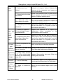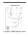
1
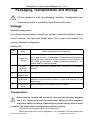
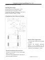
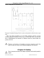
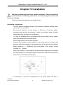
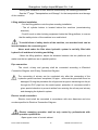
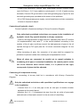
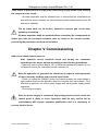
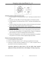
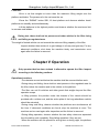
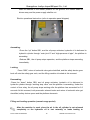
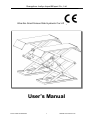
Guangzhou Junliye Import&Export Co., Ltd.
Ultra-thin Small Scissor Slab Hydraulic Car Lifting Machine
User ’s Manual
Phone: 0086-20-86394322
1
Website:www.431tool.com
Guangzhou Junliye Import&Export Co., Ltd.
Contents
Packaging, Transportation and Storage.................................................................3
Chapter Ⅰ: Description of Machine........................................................................4
Chapter Ⅱ: Specification Parameters.................................................................... 5
Chapter III Safety....................................................................................................... 7
Chapter IV Installation............................................................................................. 11
Chapter V Commissioning......................................................................................14
Chapter V Operation............................................................................................... 17
Chapter VI Care and Maintenance....................................................................... 19
Chapter VII Faults and Troubleshooting.............................................................. 21
Annex 1......................................................................................................................23
Warranty Certificate................................................................................................. 25
Phone: 0086-20-86394322
2
Website:www.431tool.com
Guangzhou Junliye Import&Export Co., Ltd.
Packaging, Transportation and Storage
All the operations such as packaging, handling, transportation and
dismounting shall be operated by specialized technicians.
Package
Standard Configuration:
One oil pipe and accessory; one primary platform, secondary platform, one of
control console, four approach bridge slabs, five oil pipe cover plates, five
kinds of standard configuration.
Packing List:
Carton
No.
1.
2.
3.
4.
5.
Name
Oil pipe and
fittings
Lifting
platform
(1P、2P)
Operation
cabinet (EX)
Approach
bridge slab
Name and Quantity of Accessories
12 sets of M16 ground screw; 1 set of φ6×4mm air pipe (contains
one air pipe tee joint); 4 foam pads; 1 Operation and Maintenance
Manual; 10 nylon cable ties; 10 short oil pipes; 3 long oil pipes; 20
sets of M8 ground screw; 1 angle guard board welding; 2 ¢ 8
bonded washer (customer spare)
One piece of primary platform and one piece of secondary
platform
4 approach bridge welding, 4 approach bridge connecting shaft, 8
approach bridge travelling wheels, 16 φ20 snap springs, 8 φ10
snap springs
Oil pipe cover One of 730MM, two of 630MM, three of 750MM
plate
Transportation
Goods shall be handled and moved by crane and fork lift truck weighing
over 1 ton. To prevent goods from falling down, during the lifting operation,
one person shall be in charge of observing the goods intently, so as to avoid
accidents. The goods shall be transported by vehicles or liners.
The goods are transported by truck or steamship.
When the goods arrive at the destination, it is necessary to check whether the
Phone: 0086-20-86394322
3
Website:www.431tool.com
Guangzhou Junliye Import&Export Co., Ltd.
goods are complete to prevent damage and loss during the transportation. If
there is any damage in the package, inspection to the damaged box shall be
conducted by the Encasement List to confirm the situation about the damage
and loss of goods. Meanwhile, it is necessary to notify the person that
undertakes the transportation immediately.
The machine is heavy goods! Manual loading, unloading and handling shall
be beyond the consideration, safety during the operation is of great
importance.
Storage:
The machinery and equipment shall be placed in indoor warehouse and
outdoor storage shall make good water-proof treatment.
Van truck shall be adopted during the transportation and goods shall be stored
in containers if they are shipped by liners.
The control panel shall be kept upright during the transportation; in addition,
extrusion of goods shall be avoided.
Environmental temperature for storage of machine: -25℃~55℃.
The manufacturer keeps the right of the minor modification of the manual
due to advancement of technology
Chapter Ⅰ: Description of Machine
Machinery Application
Ultra-thin small scissor slab hydraulic car lifting machine can lift various cars of
no more than 3000kg. It is suitable for car service, repair, tire removal and
maintenance for car maintenance enterprises, especially appropriate for being
used in basement or on the upper floor, there is no need for construction pit.
Structural Characteristics
- Adopt hidden scissor ultra-thin structure, there is no need for construction pit,
and it takes up small space.
-With independent control cabinet and low-voltage control, the safety
performance of the machine is excellent
-With hydraulic capacity synchronous oil cylinder, the operation of platform is
synchronous and stable
-With double safety devices of hydraulic lock and mechanical double-tooth safety
claw, it is safe and reliable.
Phone: 0086-20-86394322
4
Website:www.431tool.com
Guangzhou Junliye Import&Export Co., Ltd.
-The machine adopts good quality hydraulic and electric components from Italy,
Germany and Japan, etc.
The machine is configured according to the following assembly conditions:
-Foundation of machine (position for equipment installation and space)
-Frame of lifter (main structure of lifter and safety mechanism)
-Control cabinet (control part of the machine)
Basic structure
The foundation of machine is composed by concrete structure.
Frame of lifter
It is composed by solid steel connecting leveler, main lifting platform, pneumatic
double-tooth safety components and hydraulic oil cylinder components.
Control cabinet
At the bottom of the control panel, there is a hydraulic control system such as
hydraulic oil tank, hydraulic pump, hydraulic motor and hydraulic valve, etc.
While the upper part is electrical control system
Scissor Lifter is designed to lift vehicles. It is not suitable for other occasions,
especially for operation of washing and spraying. In addition, it shall not lift things
heavier than the rated load.
Chapter Ⅱ: Specification Parameters
Major technical parameters:
Model
8230CJ
Maximu
Maximum
m Lifting
Lifting
Capacity
Height
3000Kg
1850mm
Initial
Platfor
Platform
Platfor
m
Length
m Width
Height
110mm
1450mm
635mm
Liftin
g
Time
≦50S
Whole
Whole
Machin
Machin
e
e
Weight
Length
850Kg
1820mm
Whole
Machine
Width
2020mm
Electrical Parameters: Electrical Machine: 2.2Kw 2800r/Min
Supply Voltage: Standard Configuration: 380V 50Hz, different requirements of
voltage grade can be customized based on needs of clients.
Machinery Noise: ≦70db
Hydraulic Pump Station:
Air Supply Pressure: 6-8kg/cm2
Rated Flow: 2.1cc/r, Maximum Working Pressure: 30Mpa
Hydraulic oil: 14L; winter 20# antiwear hydraulic oil; summer 46# antiwear hydraulic oil;
Phone: 0086-20-86394322
5
Website:www.431tool.com
Guangzhou Junliye Import&Export Co., Ltd.
(hydraulic oil is provided by clients)
Operating Environment:
Working Environment Temperature: 5-40oC
Working Environment Humidity: 30-90%
Transportation/Storage Temperature: -25 oC-55 oC
Machine Installation Height:≦2000M
Lifting Machine Outline Dimension Drawing:
Attention: Basic requirements
- Concrete type is 425#, the dry period
is 15 days
-Remove
the
internally
generated
surface in the foundation pit, the
thickness of concrete at the pit bottom is
≥200mm, The levelness is ≤5mm
Provide the following at the same time:
-Connect to the power of the control panel
(400V or 230V 15 A)
-Connect to the compressed air inlet tube on
the control
panel (Ф8×6mm)
Phone:
0086-20-86394322
6
Website:www.431tool.com
Guangzhou Junliye Import&Export Co., Ltd.
Scissor Lifting Machine Installation Plan
Equipment Foundation Drawing (Control console can be placed on either left side or right
side)
Note: The bottom foundation of P1, P2 lifting platforms shall be concrete
structure. Where the thickness of indoor floor is no more than 20mm, concrete with
area of 2500×2500mm and thickness of ≥200mm should be poured under the
position of P1, P2.
Thickness and levelness of foundation concrete is extremely crucial. One
shall not expect too much of level adjusting capability of the machine.
Chapter III Safety
There is important content in this chapter. Operators shall carefully read this
chapter.
Phone: 0086-20-86394322
7
Website:www.431tool.com
Guangzhou Junliye Import&Export Co., Ltd.
The following content is explanation and description about danger and the
possible danger during the operation, the correct effect and description of
safety devices of equipment, other dangers, correct operating rules and
potential dangers, etc.
The designing and manufacturing of lifter is intended for hoisting and
maintenance of vehicles. It is inappropriate for the hoisting of other goods. It
is suitable especially for the following operation:
-Washing and cleaning of vehicles
-The hoisting operation where there are persons on the platform
-The hoisting operation of goods in bulk or broken goods
-It is applied as the elevator
-It is applied in vehicles with severely tilt frame or severe deformed tire
The manufacturer bears no liability for personal injury or loss of property
caused by incorrect operation or operation that violates the operating rules.
During the falling, operator shall operation within the safety area shown in the
diagram.
As is shown in the diagram, operations by operator or other irrelevant
personnel within this dangerous area are strictly forbidden.
Only when the vehicle is completely hoisted to the required position and the
operation platform becomes still and the safety devices of the machine is
completely prepared (such as the insurance gear is fully locked), can the
operator and maintenance personnel be permitted to conduct operation under
the vehicle.
Lifter shall never be used when there are no safety protection devices
The might be casualty of personnel, damage of machine and damage of the
vehicle that is to be hoisted if the operating rules mentioned above are not
observed.
Overall Prevention
Operator and maintenance personnel shall operate the machine according
to the ordinance on safety formulated by the country where the lifter is
located.
In addition, operator and maintenance personnel shall:
-Conduct operation in the safety area required in the manual.
-Make no alteration of the safety devices casually.
-Read carefully the safety warnings on the machine and the safety information
in the manual.
Phone: 0086-20-86394322
8
Website:www.431tool.com
Guangzhou Junliye Import&Export Co., Ltd.
Safety protection device
When the vehicle is on the hoisting platform, operator and maintenance personnel
shall check the possible danger, the manufacturer also shall adopt various protection
devices to avoid and reduce the occurrence of dangers as possible.
The safety of personnel and vehicle shall operate according to the following rules:
-When the vehicle-hoisting, operator and maintenance personnel shall never
enter the non-safe working area (in the lower part of the machine and the
vehicle)
-Make sure that the vehicle is at the correct position on the platform
-Make sure only vehicles with weight, height and length being within the
permitted scope of weight, maximum height and length can be hoisted.
During the vehicle-hoisting, personnel shall never stay on the platform
The potential dangers during vehicle-hoisting:
The following safety devices are intended for protecting overloading or
mechanical failure protection:
Under the situation of overloading, the overflow valve at the pump station will
open and return oil into the oil tank.
Safety rack and gear and rack set of host guarantees personnel under the
machine when other protection measures fail. It is necessary to make sure the
safety gear and rack set is of perfect occlusion and the integrality of safety gear
and rack set is good.
There shall not be any foreign body on the assurance component so that the
safety teeth can engage normally.
Danger of extrusion
Danger caused by personnel’s failure in leaving the area mentioned above
according to the rules when the lifter is hoisting or falling.
No personnel can work under the moving parts of the machine when the lifting
platform is hoisting or falling. Personnel shall stay in safety position.
Danger of impact
Operator can conduct hoisting and falling of the lifter when he/she has confirmed
that there are no personnel within the dangerous area. Meanwhile, when the lifter is at a
rather low height (less than 1.75 meter from the ground), since there is no color on the
machine, impact of collision of personnel due to no color on the machine, shall be
Phone: 0086-20-86394322
9
Website:www.431tool.com
Guangzhou Junliye Import&Export Co., Ltd.
avoided.
Danger of personnel falling down
There shall be no personnel on the lifting platform or inside the vehicle that is to be
hoisted when the lifter is hoisting or falling, so as to prevent them from falling.
Danger of vehicle-falling:
Danger caused when vehicle is placed at the incorrect position, the over-weight of
vehicle and the dimension of vehicle is not in accordance with standards.
Never start the engine of vehicle to conduct hoisting or falling and testing on
the
lifting platform.
Never lay articles at the falling area and moving parts of the lifter.
Danger of sliding:
Danger of personnel slipping due to oil pollutant on the ground in the surrounding
of the lifter, the lower part of the lifter or the surrounding area and platform shall be
clean. If there is oil pollutant, please remove it immediately.
Danger of electric-shock:
Danger of electric shock caused by damage of insulation of electrical equipment
Never use water and steam, etc. to clean the machine, never use solvent or paint,
etc. to approach the control panel of the lifter
Danger caused by insufficient lighting:
Operator and maintenance personnel shall install lighting required for working
area of lifter operation in the corresponding position to prevent loss of parts and
personal danger due to insufficient light.
Operator shall constantly observe the lifter and conduct operation within the
position of operator due to hoisting and falling.
A rubber gasket should be arranged on the lower part of the chassis while lifting
the vehicles
Never move the safety devices, Hoist weight shall not exceed the maximum
hoist capability required for the machine and make sure that the machine is not
over-loaded
Phone: 0086-20-86394322
10
Website:www.431tool.com
Guangzhou Junliye Import&Export Co., Ltd.
Chapter IV Installation
Only the specialized personnel can conduct installation. They shall carefully
read and follow the following instructions to avoid damage of machine and
personnel casualty.
Only the authorized technicians can install the lifter.
Installation requirements:
The lifter shall be installed according to the specified distance between walls,
columns and other facilities.
The minimum distance to wall surface is 1000 mm. To prevent against
emergency and provide convenience to work, the sufficient space of safety
channel shall also be taken into consideration.
The site for installation shall be equipped with power supply and air supply,
which are connected to the control panel.
Indoor height shall be no less than 4000mm.
However, the machine can be installed in any indoor ground, as long as the
ground is level and coincident to the requirements and the ground has sufficient
weight tolerance ( ≧ 250kg/cm2, and the thickness of the horizon cement
concrete is ≧ 200mm)
When the machine is to be installed, there shall be enough light to guarantee
the safe operation of commissioning and maintenance and avoid the eyestrain
of personnel caused by stimulated light.
It is necessary to check the completeness of the goods before the lifter is
installed.
Phone: 0086-20-86394322
11
Website:www.431tool.com
Guangzhou Junliye Import&Export Co., Ltd.
Moving and installation of lifter shall be conducted by the following processes.
See the 3rd page “Transportation and Storage” for the transportation and storage
of the machine
Lifting platform installation
- Put the lifting platform onto the place needing installation.
- The oil cylinder bottom is located behind the machine (commissioning
direction).
- Fork lift truck or other hoisting equipment hoists the lifting platform; to ensure
that the safety device of the machine is on and locked.
To avoid failure of safety device of the machine, one wooden block can be
inserted between the connecting rod.
Never work under the lifter when hydraulic system is not fully filled with
hydraulic oil and there is hoisting and falling.
- Move the lifting platform, adjust the distance between the two platforms and
make sure the two platforms are in parallel position.
Pipe connection:
The circuit, oil-way and gas-way shall be connected according to Electrical
Connection Diagram and Oil-way Connection Diagram.
The connecting of air-way can be conducted only after the connecting of the
hydraulic system has been completed, Oil pipe、wires and air pipe shall never be
damaged, During the procedure the oil pipe and air pipe is traversing into the pit
through the PVC pipe from the control panel, protection of connectors shall b
given special attention to prevent rarities from entering the oil-way and air-way
and damaging the hydraulic system.
Electric circuit connection:
Electric circuit shall be connected in accordance with wire diameters and wire
number specified in Electrical Connection Diagram.
Electric mounting operation shall be only carried by professionals with
electric operation qualification.
-Open upper cover of control cabinet
Phone: 0086-20-86394322
12
Website:www.431tool.com
Guangzhou Junliye Import&Export Co., Ltd.
- Power cord connection: connect 380V three-phase four-wire system power
cord (3×2.5mm2+2×1.5 mm2 cable) to control panel L1, L2,L3, N and incoming
terminals; Connect PE ground wire to stud with grounding sign (Figure 25) and
stud with grounding sign provided at the bottom of two platforms.
-If it is 230V three-phase power supply, control transformer and wire connection
of motor is required to adjust.
Connecting of hydraulic circuit
Connect hydraulic oil pipes according to Oil-way Connection Diagram.
Only authorized specialized technicians can engage in the installation of
hydraulic circuit, Pay special attention to oil pipe connector.
- Lead out the high-pressure oil pipe from the “operation stop valve G” and the
“oil supplementation stop valve F” in the control platform according to the
number of the oil pipe, and then connect the high-pressure oil pipe to the oil
cylinder through a PVC pipe (see the “oil circuit connection diagram” for the
details”)
- When traversing oil pipe, the connector of air pipe shall be wrapped for
protection to prevent rarities from entering the compressed air circuit.
When oil pipes are connected, be careful not to commit mistakes in
numbering of oil pipes. In standard installation, the control panel is at the
left of the direction when vehicle enters, if it is placed on the right,
correspond oil pipes shall be adjusted.
Connecting of compressed air-way:
The connecting of air-way shall be in accordance with Air-way Connection
Diagram.
Only the authorized technicians with specialized qualifications can engage
in the installation.
- Connect the Φ 8 × 6 air inlet pipe to the air inlet port of double oil-water
separator at the control panel
-Introduce the Φ 6 × 5 compressed air pipe from the air outlet of pneumatic
solenoid valve of host and connect it to the air valve of claw-lifting
Phone: 0086-20-86394322
13
Website:www.431tool.com
Guangzhou Junliye Import&Export Co., Ltd.
-Take notice of protection of air pipe joints, preventing foreign matter from entering
the compressed air circuit.
- Oil-water separator shall be installed prior to connecting the compressed air
pipe with the control console, so that extend pneumatic components service life
and action reliability.
The air pipes shall not be broken, knotted to prevent gas circuit from
impeding or blocking.
Oil-water separator shall be installed before connecting the compressed air
intake pipe with the pneumatic solenoid valve air intake in the control console,
preventing the pneumatic unit from action failure.
Chapter V Commissioning
Add oil and check phase sequence:
After hydraulic circuit, electrical circuit and air-way are connected
according to the annex, operate according to the following procedures:
- Open the control cabinet and fill 18L of 20# wear-resistance hydraulic oil into
oil tank with funnel (the user shall provide hydraulic oil)
When fill hydraulic oil, guarantee its cleanliness in order to avoid unsmooth
oil-way caused by sundries and solenoid valve failure
- Power on, press the “RISING” button and check whether the motor keeps a
right rotation direction (the direction shall be clockwise from up to down). If the
direction is opposite, cut off the power supply and adjust power supply phase
sequence
- Connecting air supply.
After the power supply is connected, high-voltage electric shock inside the
control panel is likely to occur. Operation shall be only carried out by
professionals with electric operation qualification and it is necessary to
prevent electric shock.
Phone: 0086-20-86394322
14
Website:www.431tool.com
Guangzhou Junliye Import&Export Co., Ltd.
Oil Refill and Exhaust Adjustment Procedure:
1. Pull the handles of “oil refill stop valves H” and “I” until they are vertical to the oil
pipe.
2. Press the “up” button SB1 to lift up the lifting platform to the highest position.
3. Pull the handles of “oil refill stop valves H” and “I” until they are paralleled to the
oil pipe.
4. Loosen the bleed screw above the master cylinder (the thicker one) to exhaust
the air in the master cylinder and then screw up the screw.
5. Switch off the “oil refill stop valves H” and “I” (pull the handles until they are
vertical to the oil pipe).
6. Press the “down” button SB3 to lower the lifting platform to the lowest position.
7. Then lift up the lifting platform to the highest position. Repeat 3-6 adjustment
steps until there is no air to be exhausted from the bleed screw.
8. Descend the lifting platform, and oil refill and exhaust adjustment is completed.
If the platform is not leveled, it shall be adjusted slightly as follows:
Platform Horizontal Adjustment Procedure:
A. Lift up the platform by about 500mm
B. Pull the “oil refill stop valves H” and “I” until they are paralleled to the oil pipe.
C. Press the “up” button and pull the handles of “H” or “I” until it is vertical to the oil
pipe when two levels are completely consistent.
Inspection: whether the safety device of the two safety claws operates
agilely and reliably and whether there exits leakage of oil-way and gas-way
Phone: 0086-20-86394322
15
Website:www.431tool.com
Guangzhou Junliye Import&Export Co., Ltd.
Installation of foundation bolt:
The construction of foundation bolt shall be undertaken after the expiration
of maintenance for concrete. Otherwise the strong quality shall be affected.
- Adjust the left and right platform in alignment and the distance of the two
platforms according to the requirements.
- Impact drill hammer ofΦ18 shall be drilled to the deep hole of 120mm from
ground through base hole of platform with electric hammer pinch and entrance
to hole shall be cleaned.
- Foundation bolt shall be installed in the holes with light hammer (without
installing the central expansion nail of foundation, it shall be installed after
leveling adjustment is completed.
Horizontal Adjustment:
- Use gradienter or horizontal pipe to detect levelness of the platform
-If it is caused by unevenness of foundation, iron blocks can be used to pad the
lower position
-After the horizontal adjustment is completed, insert ground screw central
expansion nail, heavily hammer down the expansion nail and screw up the ground bolt
and nut.
When the guarantee period of concrete is not expired and central
expansion nail of foundation bolt shall not be installed.
After leveling, the space between base plate and ground shall be filled
with cement mortar.
No-load Test:
-Press the “up” button SB1, and observe whether two platforms ascend steadily
and synchronously.
-Observe whether safety claw is able to accurately fall down to the correct
position, if there is air leakage and oil spilling in the gas circuit and the oil circuit
respectively.
During test, there shall not be persons and other articles in the lifter rising
and falling or regulated area. For any abnormal conditions, shut power
supply general switch and commission once again after the failure is removed
Phone: 0086-20-86394322
16
Website:www.431tool.com
Guangzhou Junliye Import&Export Co., Ltd.
Load test:
-Drive a car that weighs not more than the maximum lifting weight onto the
platform and brake. The personnel in the car leave the car.
-Press the “RISING” button SB1, lift host platform and observe whether hosts’
platforms rise steadily and simultaneously.
-Lift the platforms to the highest position and observe whether the maximum limit
is accurate and reliable.
During test, there shall not be persons and other articles in the lifter rising
and falling or regulated area.
The weight of tested vehicle can not exceed the minimum lifting capacity of the lifter
Inspect whether there exists oil or gas leakage in oil-way and gas-way. For any
abnormal conditions, shut down the machine timely and commission once
again after the failure is removed.
Chapter V Operation
Only operator that has been trained is allowed to operate the lifter. Inspect
according to the following cautions.
Operational cautions
-The obstacle around and below the machine shall be removed before work.
-During rising and falling, there shall not exist persons in the regulated area for
the lifter, below the machine and in the vehicle on the platform.
-The lifter can not lift vehicles and other goods that weighs beyond the lifter
operation scope.
-In lifting process, the position under the chassis of the vehicle should be
provided with a rubber mat, and the active plate of the long wheelbase vehicle
should be extracted.
-During rising and lifting, observe whether the platforms are simultaneous all
the time. If abnormal conditions are found, stop the machine at once. The
machine can be used again after inspection and the failure is removed.
-During falling operation, observe whether the two safety claws are separated
form the safety rack completely. Stop falling operation if they are not.
-When the machine will not operate for a long time or during night, the platform
Phone: 0086-20-86394322
17
Website:www.431tool.com
Guangzhou Junliye Import&Export Co., Ltd.
shall be lowered to the lowest position on the ground, the vehicle shall be
driven away and the power supply shall be cut.
Electric operational instruction: (refer to operation panel diagram)
Ascending:
-Press the “up" button SB1, and the oil pump activates, hydraulic oil is delivered to
hydraulic cylinder through “main joint G” and “high-pressure oil pipe”, the platform is
ascending.
-Release SB1, the oil pump stops operation, and the platform stops ascending
immediately.
Locking:
Press “SB2”, return oil solenoid valve gets electrified, and the safety device goes
back off onto the safety gear rack; and the lifting machine is locked at this moment.
Descending:
-Press the “down" button SB3, and oil pump activates, hydraulic oil is delivered to
hydraulic cylinder through “working stop valve” and the platform is ascending. Under the
control of time relay, the oil pump stops working after the platform has ascended for 2-3
seconds. At this moment, both pneumatic solenoid valve and return oil solenoid valve get
electrified, safety device opens and the platform descends.
Filling and leveling operation (normal usage period)
After the machine is used, since the air in the oil cylinder is not released
completely or the hydraulic oil is lost naturally or leaks leading to
Phone: 0086-20-86394322
18
Website:www.431tool.com
Guangzhou Junliye Import&Export Co., Ltd.
unevenness of the two platforms, filling adjustment shall be conducted.
There shall not be any load on the platform during filling and leveling
Adjustment Procedure:
A.
Lift up the platform by about 500mm
B. Switch on the oil refill valve of the platform whichever is at lower position
(pull the oil refill stop valve until it is paralleled to the oil pipe). Press the
ascending button until two platforms are at equal altitude and then switch off
stop valve (pull the stop valve until it is vertical to the oil pipe), the oil refill
adjustment procedure is completed.
Chapter VI Care and Maintenance
Lifting machine maintenance shall be performed by trained operating
personnel
Ⅰ. Daily: A: Often wipe and clear the machine to keep it clean.
B: Keep working environment clean and clear away obstacles and oil stain on
the floor.
C: Check the integrity of various safety devices, ensuring the action is flexible
and reliable.
D: Check the machine for air and oil leakage.
Ⅱ. Weekly:
All twisted axis areas of the machine shall be lubricated with engine oil by
using engine oil pot once a week.
Ⅲ. Monthly:
A: The safety gear-rack and moving parts of top-and-bottom slideway shall
be lubricated with lubricating grease once a month.
B: Check the ground bolt for any looseness and screw it up if any.
C: Check all pipelines for wear condition and leakage condition.
Ⅳ. Yearly:
A: Change hydraulic oil one a year and ensure upper limit of oil level all the
time.
B: Fully check all components for possible wear, interference and damage
Phone: 0086-20-86394322
19
Website:www.431tool.com
Guangzhou Junliye Import&Export Co., Ltd.
thoroughly.
C: Check slide blocks for wear condition, lubricating grease shall be applied
in time if the wear of blocks occurs.
D: Check oilless bearings of various nodes for intactness.
While changing hydraulic oil, the machine shall be descended to the
lowest position, and the old oil in the oil tank shall be fully discharged
and filter shall be used when filling new oil.
The Storage after usage
When the machine is shut down or not being used for a long time:
A: Cut off the power and air supply.
B: Lubricate contact parts of all components
C: Fully discharge hydraulic oil in the oil cylinder, oil pipe and oil
tank.
D: The machine shall be shielded with dust cover.
Phone: 0086-20-86394322
20
Website:www.431tool.com
Guangzhou Junliye Import&Export Co., Ltd.
Chapter VII Faults and Troubleshooting
Machine faults solving shall be undertaken by operators having been
trained with professional experience.
Fault phenomenon and troubleshooting:
Fault
phenome
non
Phenomenon and
reasons
① Abnormal power
supply or zero line
② AC connector of main
Motor fails circuit for motor of pump is
not connected
to rotate
upon
pressing
rising
Troubleshooting
After inspecting and eliminating, wires are
connected
If motor shall operate after pressing motor by
insulating rod, inspect control circuit. If the
voltage of coil end for contactor is normal,
contactor is replaced.
③Fault in limit switch
occurs
If the faults are eliminated after the terminals
connecting limit switch of 102# and 100# is
short connected via wire, such limit switch
and shall be inspected. Meanwhile, limit
switch shall be adjusted or replaced.
④ Button switch is
damaged
Inspect contact point of button and wire for
eliminating.
① Motor rotates in
reverse
Change incoming sequence of power supply
Heighten the safety pressure setting of
Motor can ②Motor shall rise with
overflow valve by slightly screwing right. If
rotate but light load and it fails to rise there is dirt in the falling solenoid valve plug,
with heavy load
clean the plug.
fail to rise
upon
pressing
rising
②Hydraulic oil is not
sufficient
Fill hydraulic oil.
④ The releasing screw of
solenoid valve for falling is
not be screwed down
Screw down the releasing screw of solenoid
valve for falling
Lifter fails ① Safety claw is not
The platform shall be lifted a little , then lower
to fall after separated from safety rack the platform.
Phone: 0086-20-86394322
21
Website:www.431tool.com
Guangzhou Junliye Import&Export Co., Ltd.
pressing
down
button
② Safety claw is not
hoisted
Air pressure is insufficient, safety claw is
blocked, or air pipe is broken. Regulate the
pressure of air compressor and inspect air
pipe for eliminating
Where since solenoid valve is power on but
③ Solenoid air valve does
fails to operate, air circuit is not connected.
not operate
Inspect or replace solenoid valve
Inspect the plug of solenoid valve in falling
④
Solenoid valve in
and coil and inspect whether the copper nut
falling does not operate
on the end is screwed or not
Remove the “explosion-proof valve” in oil inlet
⑤ Explosion-proof valve
hole at the bottom of oil cylinder of host or
is blocked
sub-machine and clean it
① Viscosity of hydraulic
Lifter falls oil is too strong or frozen,
goes bad(winter)
slowly
under
normal
load
Left and
right
platform
are out of
Replace with hydraulic oil or improve the
temperature indoor according to the
requirement of user’s manual
Remove or close air inlet pipe to make the
② “Explosion-proof valve” safety claw of lifter is locked without hoisting.
preventing oil pipe from
Remove the “explosion-proof valve” in oil inlet
crack is blocked off
hole at the bottom of oil cylinder of host or
sub-machine and clean it
① Air in oil cylinder is not
Refer to the filling and leveling operation
exhausted
② There is oil leak in oil Screw on the connector or replace oil seal.
pipe or connector
Then filling and leveling are conducted
③ “Filling-ending valve G
or H” is not closed tightly Replace filling-ending valve and filling and
unequal in
and filling is needed nearly leveling are conducted
height
every day
sync and
Sound is
① Lack of lubricating
generated
when
lifting and
Oil machine is applied to all hinged place and
moving part(including piston) for lubricating
② Base or machine is Adjust and level machine again and fill (pad)
distorted
the base
falling
Phone: 0086-20-86394322
22
Website:www.431tool.com
Guangzhou Junliye Import&Export Co., Ltd.
Annex 1
Oil circuit Connection Diagram
A.
Descending solenoid valve, B. Manually descending knob, C. Solenoid valve
coil, D. Pump motor, E. Overflow valve, F. Motor junction box, G. Main joint , I. oil
refill stop valve, H. oil refill stop valve, 1~9. high-pressure oil pipes
Phone: 0086-20-86394322
23
Website:www.431tool.com
Guangzhou Junliye Import&Export Co., Ltd.
Annex 2
Electrical Equipment Schematic Diagram
Gas circuit Connection Diagram
Phone: 0086-20-86394322
24
Website:www.431tool.com
Guangzhou Junliye Import&Export Co., Ltd.
Warranty Certificate
Product Warranty Card
Dear Customers:
From the date of purchase of this product, you will enjoy our all-round services, and
we also expect to receive your precious opinions on our quality of products and services.
After-sales service commitments:
1. Warranty period for our product shall last for 1 year from the date of installation for
use under normal application.
2. After-sales services within warranty period are absolutely free (expect for
consumptive parts).
3. Provide lifelong services beyond warranty period (it is charged at cost price).
4. Following circumstances are not within the warranty scope:
A: Unable to provide the warranty card or the warranty card is provided without
manufacturer’s or dealer’s seal.
B: Abnormal use of the product, without following the operating procedure.
C: Discretionally change the structure of the machine.
D: The product’s spraying surface being scratched.
E: Service life is beyond warranty period.
Please fill out the warranty card and keep it properly
Warranty Card Copy
Product Model
Product Name
Ex-factory Date
Ex-factory No.
Installation
Installation Time
Personnel
Place of
Telephone No.
Purchase
User
Telephone No.
Dealer
Manufacturer
Phone: 0086-20-86394322
25
Website:www.431tool.com