1
Section 2
DP2000T SETUP
Installation
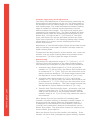
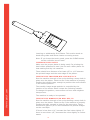
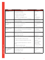
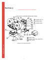
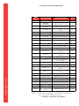
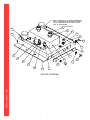
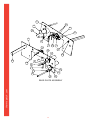
SEE PAGE 25 Loosen the two screws on the top of the case
in the back and install control box bracket,
Item 5.
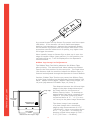
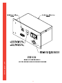
Insert the control box, Item 6, with the LCD up
and pointing to the front of the machine.
Plug one side of the coil cable, Item 20, into the
control box, Item 6, connector.
Plug the other end of the coil cable, Item 20, into
the connector on the side of the machine.
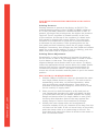
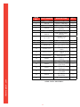
SEE PAGE 45 Turn “Emergency Stop” switch, Item 4, in the
direction of the arrow to make sure it is out.
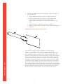
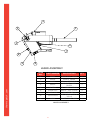
SEE PAGE 48 - 49 Attach air filter/regulator, with fittings to
the bulkhead fitting, Item 5, on the back of the
machine. Orient as shown with the gauge facing
forward.
Connect air supply to the male hose adaptor,
Item 4.
SEE PAGE 52 Connect the foot pedal plug into the
connector, Item 3 on right side of machine.
Connect power line cord to the machine power
entry module, Item 4, and to power outlet.
Turn on the machine by pressing the rocker
switch on the power entry module, Item 4, on
the right side of the machine as viewed from the
front.
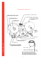
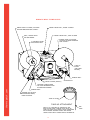
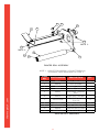
SEE PAGE 35 - 36 Place flange assemblies on supply and
take-up shafts.
thermopatch.com
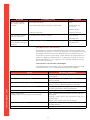
Refer to pages 12 and 13 to set-up for transfer
roll or ribbon (c-tape) roll
DP2000T SHIPMENT
Reverse setup procedure shown above.
A check valve between air supply and air cylinder will prevent
head from lowering. To lower head, Remove Cover, top rear,
Item 3, see page 25. With a pen or other tool, push button on
air solenoid to relieve pressure to air cylinder. The air solenoid
is located on the left side at the rear of the machine, slightly
forward of the cover opening. See page 48-49.
The machine should be shipped in a suitable shipping
container, preferably, the one it was received in.
11