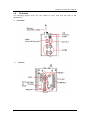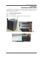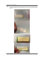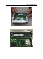
1
rBOX310-FL Series Robust Din-rail Fanless Embedded System User’s Manual Disclaimers This manual has been carefully checked and believed to contain accurate information. Axiomtek Co., Ltd. assumes no responsibility for any infringements of patents or any third party’s rights, and any liability arising from such use. Axiomtek does not warrant or assume any legal liability or responsibility for the accuracy, completeness or usefulness of any information in this document. Axiomtek does not make any commitment to update the information in this manual. Axiomtek reserves the right to change or revise this document and/or product at any time without notice. No part of this document m ay be reproduced, stored in a retrieval system, or transmitted, in any form or by any means, electronic, mechanical, photocopying, recording, or otherwise, without the prior written permission of Axiomtek Co., Ltd. Copyright 2013 Axiomtek Co., Ltd. All Rights Reserved December 2013, Version A1 Printed in Taiwan ii Safety Precautions Before getting started, please read the following important safety precautions. 1. The rBOX310-FL does not come equipped with an operating system. An operating system must be loaded first before installing any software into the computer. 2. Be sure to ground yourself to prevent static charge when installing the internal components. Use a grounding wrist strap and place all electronic comp onents in any static-shielded devices. Most electronic components are sensitive to static electrical charge. 3. Disconnect the power cord from the rBOX310-FL before making any installation. Be sure both the system and the external devices are turned OFF. Sudd en surge of power could ruin sensitive components. Make sure the rBOX310-FL is properly grounded. 4. Make sure the voltage of the power source is correct before connecting the equipment to the power outlet. 5. Turn OFF the system power before cleaning. Clean the system using a cloth only. Do not spray any liquid cleaner directly onto the screen. 6. Do not leave this equipment in an uncontrolled environment where the storage temperature is below -45℃ or above 85℃. It may damage the equipment. 7. Do not open the system ’s back cover. If opening the cover for maintenance is a must, only a trained technician is allowed to do so. Integrated circuits on computer boards are sensitive to static electricity. To avoid damaging chips from electrostatic discharge, observe the follo wing precautions: Before handling a board or integrated circuit, touch an unpainted portion of the system unit chassis for a few seconds. This will help to discharge any static electricity on your body. W hen handling boards and components, wear a wrist -grounding strap, available from most electronic component stores . iii Classification 1. Degree of production against electric shock: not classified 2. Degree of protection against the ingress of water: IP30 3. Equipment not suitable for use in the presence of a flammable anesthetic mixture with air or with oxygen or nitrous oxide. 4. Mode of operation: Continuous 5. Type of protection against electric shock: Class I equipment General Cleaning Tips You may need the following precautions before you begin to clean the computer . W hen you clean any single part or component for the com puter, please read and understand the details below fully. W hen you need to clean the device, please rub it with a pi ece of dry cloth. 1. Be cautious of the tiny removable components when you use a vacuum cleaner to absorb the dirt on the floor. 2. Turn the system off before you start to clean up the component or computer. 3. Never drop the components inside the computer or get cir cuit board damp or wet. 4. Be cautious of all kinds of cleaning solvents or chemicals when you use it for the sake of cleaning. Some individuals may be allergic to the ingredients. 5. Try not to put any food, drink or cigarette around the computer. iv Cleaning Tools Although many companies have created products to help improve the process of cleaning your computer and peripherals users can also use household items to clean their computers and peripherals. Below is a listing of items you may need or want to use while cleaning your computer or computer peripherals. Keep in mind that some components in your computer may only be able to be cleaned using a product designed for cleaning that component, if this is the case it will be mentioned in the cleaning. Cloth: A piece of cloth is the best tool to use when rubbing up a component. Although paper towels or tissues can be used on most hardware as well, we still recommend you to rub it with a piece of cloth. W ater or rubbing alcohol: You may moisten a piece of cloth a bit with some water or rubbing alcohol and rub it on the computer. Unknown solvents may be harmful to the plastics parts. Vacuum cleaner: Absorb the dust, dirt, hair, cigarette particles, and other particles out of a computer can be one of the best meth ods of cleaning a computer. Over time these items can restrict the airflow in a computer and cause circuitry to corrode. Cotton swabs: Cotton swaps moistened with rubbing alcohol or water are excellent tools for wiping hard to reach areas in your keyboard, mouse, and other locations. Foam swabs: W henever possible it is better to use lint free swabs such as foam swabs. Note: We strongly recommended that you should shut down the system before you start to clean any single components. Please follow the steps below: 1. Close all application programs 2. Close operating software 3. Turn off power 4. Remove all device 5. Pull out power cable v Scrap Computer Recycling If the computer equipments need the maintenance or are beyond repair, we strongly recommended that you should inform your Axiomtek distributor as soon as possible for the suitable solution. For the computers that are no longer useful or no longer working well, please contact your Axiomtek distributor for recycling and we will make the proper arrangement. Trademarks Acknowledgments Axiomtek is a trademark of Axiomtek Co., Ltd. IBM, PC/AT, PS/2, VGA are trademarks of International Business Machines Corporation. ® ® Intel and Pentium are registered trademarks of Intel Corporation. MS-DOS, Microsoft C and QuickBASIC are trademarks of Microsoft Corporation. VIA is a trademark of VIA Technologies, Inc. SST is a trademark of Silicon Storage Technology, Inc. UMC is a trademark of United Microelectronics Corporation. Other brand names and trademarks are the properties and registered brands of their respective owners . vi Table of Contents Safety Precautions ............................................................................................ iii Classification ..................................................................................................... iv General Cleaning Tips ....................................................................................... iv Scrap Computer Recycling ............................................................................... vi CHAPTER 1 INTRODUCTION ................................................................................. 1 1.1 1.2 1.2.1 1.2.2 1.2.3 1.2.4 1.2.5 1.2.6 1.2.7 1.2.8 1.2.9 1.2.10 1.2.11 1.2.12 1.2.13 1.2.14 1.2.15 1.2.16 1.2.17 1.2.18 1.2.19 1.2.20 1.2.21 1.2.22 1.3 1.4 General Description ............................................................................ 1 System Specifications ........................................................................ 3 CPU .................................................................................................................... 3 Chipset ............................................................................................................... 3 BIOS ................................................................................................................... 3 System Memory ................................................................................................ 3 Display ............................................................................................................... 3 Ethernet Ports ................................................................................................... 4 Storages ............................................................................................................. 4 USB .................................................................................................................... 4 COM .................................................................................................................... 5 Two power paths .............................................................................................. 6 WatchDog Timer (WDT).................................................................................... 6 Audio .................................................................................................................. 7 System LED ....................................................................................................... 7 Alarm Contact.................................................................................................... 9 Mini Card.......................................................................................................... 12 Reset Bottom................................................................................................... 12 Operation Temperature .................................................................................. 12 Storage Temperature ...................................................................................... 12 Humidity........................................................................................................... 12 Weight .............................................................................................................. 12 Dimensions...................................................................................................... 12 System I/O Outlets .......................................................................................... 13 Dimensions ....................................................................................... 14 I/O Outlets ......................................................................................... 15 CHAPTER 2 HARDWARE INSTALLATION ........................................................ 17 2.1 2.2 2.3 2.4 Installing the Memory Module .......................................................... 17 Installing the Hard Disk Drive .......................................................... 22 Installing Din-rail Mounting .............................................................. 26 Installing Wall Mounting (optional).................................................. 34 CHAPTER 3 AMI UEFI BIOS UTILITY ................................................................. 37 3.1 3.2 3.3 3.4 3.5 3.6 Entering Setup .................................................................................. 37 The Main Menu .................................................................................. 37 Advanced Features ........................................................................... 39 Chipset Feature ................................................................................. 54 Boot Type .......................................................................................... 55 Security.............................................................................................. 60 vii 3.7 viii Save & Exit ........................................................................................ 63 rBOX310-FL Series User’s Manual CHAPTER 1 INTRODUCTION This chapter contains general information and detailed specifications of the rBOX310-FL. The Chapter 1 includes the following sections: General Description System Specification Dimensions I/O Outlets 1.1 General Description The rBOX310-FL Din-rail fanless embedded systems are suitable for communications control and for protocol converter applications in critical environments. Built for rugged work environments, the rBOX 310-FL series features ® an extra low power consumption Intel ATOM ™ N2800 (1.86 GHz) processors supporting industrial temperature range of -40℃ to +70℃. Their front accessible I/O cabling is very convenient for wiring and maintenance. The rBOX310-FL series offers a VGA output, making it particularly well-suited for communication control, SCADA and industrial automation. Its compact size with D in-rail mounting allows for easy ® installation into control cabinet. Pre-installed with Linux, W indows 7 embedded, the rBOX310-FL series provides programmers with a friendly environment for developing application software at a lower cost. The rBOX310-FL is robust industrial-grade hardware design and adopts the advanced cooling system , besides, supporting the CompactFlash™, which makes it especially suitable for field control & monitoring system solution for following markets: Utility Industries (Water; Energy; Chemical Plant; Mining…) Public Transportation Industries (Traffic/ Highway Control; Train/Bus Control…) Homeland Security (Weather Monitoring/Alarm System…) Features Fanless and no internal cabling design Wide temperature operation of -40℃ - +70℃ Supports 2 10/100/1000 Ethernets with Magnetic Isolation Protection 4 COM Ports 2 Watchdog Timers LED Indicators (Power, Alarm, Ready/Active, COM …) Mini Card (3G/GPRS or Wifi) Audio(Line in & Line out) SNMP V1/V2c Support one 2.5” SATA SSD (or HDD) and one CompactFlash™ 2 power paths with terminal block and 12–48VDC Din-rail mounting Introduction 1 rBO310-FL Series User’s Manual Wall mounting (optional) Passed heavy industrial CE with FCC Part 18 testing Embedded O.S. Supported ® The rBOX310-FL not only supports W indows 7, but also supports embedded OS, ® such as W indows 7 embedded and Linux package support. For storage device, the rBOX310-FL supports one SATA SSD or HDD and one type II CompactFlash ™ slot. Intelligent AXView & SNMP V1/V2c The rBOX310 features SNMP V1/V2c support for secured network management. To streamline implementation of management applications, Axiomtek has launched exclusive “AXView” monitoring software package for customers to build their own management systems easily and quickly. Axiomtek AXView also contains a variety of easy-to-use management utilities, agent services and libraries. For more product information, please visit our global website on Axiomtek AXView http://axiomtek.com/products/ViewProduct.asp?view=1001 2 Introduction rBOX310-FL Series User’s Manual 1.2 System Specifications 1.2.1 ® Onboard Intel ATOM™ dual core N2800 (1.86 GHz) processors. 1.2.2 Chipset Intel® System Controller NM10. 1.2.3 CPU BIOS AMI (American Megatrends Inc.) UEFI (Unified Extensible Firmware Interface) BIOS. 1.2.4 System Memory One 204-pin SO-DIMM supports up to 4GB DDR3 800/1066MHz. The composition of Memory can’t support 4Gb and 8Gb by Intel Atom Cedar Trail specification limitation. 1.2.5 Display Intel GMA3600 graphics Core integrate in CPU A slim type 15-pin D-Sub connector as VGA connector VGA IO Pin Define : Pin Signal Pin Signal Pin Signal 1 Red 2 Green 3 Blue 4 N.C. 5 GND 6 GND 7 GND 8 GND 9 VCC 10 GND 11 N.C. 12 DDC DATA 13 Horizontal Sync 14 Vertical Sync 15 DDC CLK Introduction 3 rBO310-FL Series User’s Manual 1.2.6 Ethernet Ports LAN 1 and LAN 2 The board has dual RJ-45 ethernet connector which using Intel i210-IT ethernet controllers, support 1000/100/10-Base transmit rate and with 1.5KV magnetic isolation protection. Pin L1 L2 L3 L4 L5 L6 L7 L8 A B 1.2.7 Signal MDI0+ MDI0MDI1+ MDI1MDI2+ MDI2MDI3+ MDI3Active LED Speed LED 1000-Base-T 100-Base-T 10-Base-T (Yellow) (Amber) (Green) (Dark) Storages 1 x 2.5” SATA SSD (or HDD) drive bay 1 x CompactFlash TypeII slot (easy-to- access) 1.2.8 USB 2 x USB2.0 W ith power distribution control and over current protection USB Pin Define : Pin Signal USB Port 0 Pin Signal USB Port 1 1 2 3 4 VCC DD+ GND 5 6 7 8 VCC DD+ GND 5 6 7 8 1 2 3 4 USB power (5V) distribution control. Some program and sample code for USB power distribution control are offered in Windows and Linux. - W indows: Please refer it from our Axiomtek AXView which on Axiomtek’s website directly. - Linux : Please refer it from our Axiomtek’s website directly. 4 Introduction rBOX310-FL Series User’s Manual 1.2.9 COM 4 ports DB9 Pin support RS-232/422/485 W ith ESD Protection 15KV COM1,COM2 speed up to 115.2kbps COM3,COM4 speed up to 921.6kbps rBOX support jumper less design. All of the COM port interface RS232/422/485 can be selected by BIOS menu or software program. It also supports Auto Flow Control in RS485 mode Serial Port Pin Define : (DB9 Male) COM1/COM2 Pin RS-232 RS-422 RS-485 1 DCD TX- Data- 2 RXD TX+ Data+ 3 TXD RX+ -- 4 DTR RX- -- 5 GND GND GND 6 DSR -- -- 7 RTS -- -- 8 CTS -- -- 9 RI -- -- COM3/COM4 Doesn’t support RI signal Pin RS-232 RS-422 RS-485 1 DCD TX- Data- 2 RXD TX+ Data+ 3 TXD RX+ -- 4 DTR RX- -- 5 GND GND GND 6 DSR -- -- 7 RTS -- -- 8 CTS -- -- 9 N/A -- -- Introduction 5 rBO310-FL Series User’s Manual Some program and sample code for COM port interface type are offered in W indows and Linux. - W indows: Please refer it from our Axiomtek AXView which on Axiomtek’s website directly. - Linux : Please refer it from our Axiomtek’s website directly. 1.2.10 Two power paths Two DC input power sources must be same and range between 12-48V. Main power source is PWR1, Backup power source is PWR2. W hen only one power source must connect to PW R1. DC Inputs have UVP,OVP and Reverse protection. DC Terminal Block Pin Signal 1 Alarm- 2 Alarm+ 3 Shield Ground 4 Shield Ground 5 - 6 + PW R2 7 - 8 + PW R1 Note: 1.2.11 If 2 power sources aren’t same voltage and the system will be possible damage. WatchDog Timer (WDT) rBOX310 support two W atchdog timers. Those can cause system reset when timer expired. W DT 1 : one step is 1sec or 1min, 255 levels W DT 2 : one step is 250ms, 255 levels Some program and sample code for two W atchdog timers are offered in W indows and Linux. - W indows: Please refer it from our Axiomtek AXView which on Axiomtek’s website directly. - Linux : Please refer it from our Axiomtek’s website directly. 6 Introduction rBOX310-FL Series User’s Manual 1.2.12 Audio There are two audio jacks for Line in and Line out Signal Line out (Green) Line in (Blue) 1.2.13 System LED There are showed the LED’s indicators and functional descriptions. LED Name Description Color PWR1 Indicate the PWR1 input status. When the DC input is acceptable, the LED will ON. Green PWR2 Indicate the PWR2 input status. When the DC input is acceptable, the LED will ON. Green Alarm ACT/RDY The LED will ON if having below condition. 1. DC PWR1 or PWR2 is lost. (default) 2. User define event. Notice: The behavior of Alarm and Relay are the same. When the LED of Alarm is ON and the Relay will be turn on at the same time. The LED for RDY/ACT can help users to judge BIOS finish or not and the OS can normal work or not. When the BIOS finish the configuration of system, the LED will ON. After this the LED will flash when the storage is accessed. - The LED will flash when the storage i s accessed. - The LED isn’t ON for a long time, it means the system is on shutdown status. Red Yellow ANT ACT When ANT accessed data the LED will flash. Green Storages Accessed When storages accessed data the LED will flash. Green Introduction 7 rBO310-FL Series User’s Manual LED Name 8 Description Color COM1 TX When COM1 transmit data the LED will on. Green COM1 RX When COM1 receive data the LED will on. Green COM2 TX When COM2 transmit data the LED will on. Green COM2 RX When COM2 receive data the LED will on. Green COM3 TX When COM3 transmit data the LED will on. Green COM3 RX When COM3 receive data the LED will on. Green COM4 TX When COM4 transmit data the LED will on. Green COM4 RX When COM4 receive data the LED will on. Green Some program and sample code for Alarm LED and Relay Output are offered in W indows and Linux - W inodws: Please refer it from our Axiomtek AXView which on Axiomtek’s website directly. - Linux : Please refer it from our Axiomtek’s website directly. Introduction rBOX310-FL Series User’s Manual 1.2.14 Alarm Contact rBOX310 support two DC power path. W hen lost one of them will cause Alarm LED on and trigger Relay out to remote notice. W e also provide the register for user to define their event for trigger the Alarm LED and Relay. Alarm LED and Relay output have the same activity depend on DC status and register control. 1 relay output. Event : Power Fail or User define. Some program and sample code for Alarm LED and Relay Output are offered in W indows and Linux. - W indows: Please refer it from our Axiomtek AXView which on Axiomtek’s website directly. - Linux : Please refer it from our Axiomtek’s website directly. rBOX Alarm Application: Troubleshooting is very important in many applications. In the rBOX series we can provide three kinds of way for troubleshooting. Alarm LED Relay out SNMP through AXView 1. Maintenance Staff can check the Alarm LED for basic troubleshooting . Introduction 9 rBO310-FL Series User’s Manual 2. Relay output Below is a very simple application for remote notice use relay and lamp. a) Normal b) W arning 10 Introduction rBOX310-FL Series User’s Manual c) Relay wiring of rBOX Introduction 11 rBO310-FL Series User’s Manual 3. SNMP 1.2.15 Mini Card 1 x Mini Card (3G/GPRS or Wifi) 1 x SIM Card Socket under CF slot for easy to access. 1.2.16 1 x Reset bottom 1.2.17 12 Weight 1.38 kg (3 lb) 1.2.21 Humidity 5% ~ 95% (non-condensation) 1.2.20 Storage Temperature -45℃ ~ +85℃ (-49 ºF ~ +185ºF) 1.2.19 Operation Temperature -40℃ ~ +70℃ (-40 ºF ~ +158ºF), with W.T. (Memory & CF) 1.2.18 Reset Bottom Dimensions 100.6mm(3.18”) (W) x110mm(4.33”) (D) x135mm(5.31”) (H) Introduction rBOX310-FL Series User’s Manual 1.2.22 System I/O Outlets Four 9-pin D-Sub male connectors, COM1~COM4. One 15-pin D-Sub female connector for VGA. Two 1000/100/10-Base-T Ethernets with magnetic isolation protection. Two USB 2.0 connectors. Two DC Power Inputs with terminal block. Alarm Contact. One Mini Card slot (3G/GPRS or Wifi). Two Audio jackers (Line in & Line out). Note: Introduction All specifications and images are subject to change without notice. 13 rBO310-FL Series User’s Manual 1.3 Dimensions The following diagrams show you dimensions and outlines of the rBOX310-FL 14 Introduction rBOX310-FL Series User’s Manual 1.4 I/O Outlets The following figures show you I/O outlets on front view and top view of the rBOX310-FL. Front View Top View Introduction 15 rBO310-FL Series User’s Manual This page is intentionally left blank. 16 Introduction rBOX310-FL Series User’s Manual CHAPTER 2 HARDWARE INSTALLATION The rBOX310-FL is convenient for your various hardware configurati ons, such as TM Memory Module and CompactFlash card. The chapter 2 will show you how to install the hardware. It includes: 2.1 Installing the Memory Module Step 1 Turn off the system. Step 2 Loosen these screws, and remove the top cover from the system. Hardware Installation 17 rBO310-FL Series User’s Manual Step 3 18 Take the thermal pad from the package, take off the masks of the thermal pad from two sides and paste thermal pad to the buttom side of the memory module as bellow figures. Hardware Installation rBOX310-FL Series User’s Manual Step 4 Using two fingers to hold the memory module, and insert the gold colored contact into the socket. Push the module down. Step 5 The memory module is locked by two latches on the sides. We strongly recommend using “LDC737” silicone on the two sides of the memory for good ability of vibration. Hardware Installation 19 rBO310-FL Series User’s Manual Step 6 Take off the memory thermal mask from the cover back. 20 Hardware Installation rBOX310-FL Series User’s Manual Step 7 Put the cover back to the system, and fasten screws tight close the chassis. Hardware Installation 21 rBO310-FL Series User’s Manual 2.2 Installing the Hard Disk Drive Step 1 Turn off the system. Step 2 Loosen these screws, and remove the cover from the system. 22 Hardware Installation rBOX310-FL Series User’s Manual Step 3 Locate the Hard Disk Drive socket. Step 4 Loosen these screws and remove the Hard Disk Drive bracket. Hardware Installation 23 rBO310-FL Series User’s Manual Step 5 Insert the HDD into the socket until it is firmly seated. Step 6 Put the CompactFlash fixing bracket back to the system, and fasten screws TM tight close the CompactFlash fixing bracket. Step 7 Put the cover back to the system, and fasten screws tight close the chassis. 24 TM Hardware Installation rBOX310-FL Series User’s Manual Hardware Installation 25 rBO310-FL Series User’s Manual 2.3 Installing Din-rail Mounting The rBOX provides Din-rail Mount that customers can install as below: Step 1 Prepare Din-rail Mount assembling components (screws and bracket) ready. Step 2 Assembly the bracket to the system, and fasten screws tight. 26 Hardware Installation rBOX310-FL Series User’s Manual Note: Please notice the Din-rail holes with Wall-mounting holes while assembly the bracket to system. Hardware Installation 27 rBO310-FL Series User’s Manual Note: 28 The Din-rail hole drawing for rBOX310 is listed below: Hardware Installation rBOX310-FL Series User’s Manual Note: The Din-rail kit drawing is listed below: Hardware Installation 29 rBO310-FL Series User’s Manual 30 Hardware Installation rBOX310-FL Series User’s Manual Setting up rBOX by Din-rail mounting The rBOX set up by Din-rail mounting as below: Step 1 Fixing the rail firstly. Hardware Installation 31 rBO310-FL Series User’s Manual Step 2 32 Set up the rBOX on the rail by Din-rail mounting Hardware Installation rBOX310-FL Series User’s Manual \ Hardware Installation 33 rBO310-FL Series User’s Manual 2.4 Installing Wall Mounting (optional) The rBOX provides W all Mounting that customers can install as below: Step 1 Prepare Wall Mount assembling components (screws and bracket) ready. Step 2 Assembly the bracket to the system, and fasten screws tight. 34 Hardware Installation rBOX310-FL Series User’s Manual NOTE Please notice the Din-rail holes with Wall-mounting holes while assembly the bracket to system. Hardware Installation 35 rBO310-FL Series User’s Manual This page is intentionally left blank. 36 Hardware Installation rBOX310-FL Series User’s Manual CHAPTER 3 AMI UEFI BIOS UTILITY The AMI UEFI BIOS provides users with a built-in Setup program to modify basic system configuration. All configured parameters are stored in a flash-backed-up to save the Setup information whenever the power is turned off . 3.1 Entering Setup To enter the setup screens, follow the steps below: 1. Turn on the computer and press the <Del> key immediately. 2. After you press the <Del> key, the main BIOS setup menu displays. You can access the other setup screens from the main BIOS setup menu, such as the Advanced and Chipset menus. 3.2 The Main Menu Once you enter the AMI BIOS Aptio Setup Utility, the Main Menu appears on the screen. In the Main Menu, there are several Setup functions and a couple of Exit options for your selection. Use Select Screen Keys (or Move Keys) to select the Setup Page you intend to configure then press <Enter> to accept or enter its sub -menu. AMI UEFI BIOS Utility 37 rBO310-FL Series User’s Manual System Date The date format is <day> <month> <date> <year>. System Time This item shows current time of your system with the format <hour> <minute> <second>. The time is calculated based on the 24-hour military-time clock. For example, 1 p.m. is 13:00:00. Note: If system is power failure, the date and time will come back to previous setup. Note: If your computer can not boot after making and saving system changes with Setup, the AMI BIOS will reset your system to the default settings via its built-in override feature. Note: It is strongly recommended that you should avoid changing the chipset’s defaults. Both AMI and your system manufacturer have carefully set up these defaults that provide the best performance and reliability. 38 AMI UEFI BIOS Utility rBOX310-FL Series User’s Manual 3.3 Advanced Features This Advanced section allows users to configure and improve your system, to set up some system features according to your preference. You can select any of the items in the left frame of the screen to go to the sub menus: S5 RTC Wake Settings The default setting is “disable”. If the default setting is chaned for “enable”, you can set up the automatic boot time. (Please refer below graphics.) AMI UEFI BIOS Utility 39 rBO310-FL Series User’s Manual 40 AMI UEFI BIOS Utility rBOX310-FL Series User’s Manual AMI UEFI BIOS Utility 41 rBO310-FL Series User’s Manual CPU Configuration Scroll to this item and press <Enter> to view the CPU Configuration informations. (Please refer below graphics.) 42 AMI UEFI BIOS Utility rBOX310-FL Series User’s Manual Serial Port Configuration The default setting for all COM Ports are RS232. You can change the default setting by selecting the value you want in each COM Port Type. (Please refer below graphics.) AMI UEFI BIOS Utility 43 rBO310-FL Series User’s Manual H/W Monitor Scroll to this item and press <Enter> to view the monitor hardware status. (Please refer below graphics.) 44 AMI UEFI BIOS Utility rBOX310-FL Series User’s Manual Serial Port Console Redirection Only COM1 has the console redirection function. (Please refer below graphics.) AMI UEFI BIOS Utility 45 rBO310-FL Series User’s Manual If the default setting for the console redirection function is changed for [Enabled], the settings specify how the host computer and the remote computer (which the user is using) will exchange data. Both computers should have the same or compatible settings. And you can further change the setting by selecting or setting the value you want in each function as the following pictures. 46 AMI UEFI BIOS Utility rBOX310-FL Series User’s Manual AMI UEFI BIOS Utility 47 rBO310-FL Series User’s Manual 48 AMI UEFI BIOS Utility rBOX310-FL Series User’s Manual AMI UEFI BIOS Utility 49 rBO310-FL Series User’s Manual 50 AMI UEFI BIOS Utility rBOX310-FL Series User’s Manual AMI UEFI BIOS Utility 51 rBO310-FL Series User’s Manual 52 AMI UEFI BIOS Utility rBOX310-FL Series User’s Manual AMI UEFI BIOS Utility 53 rBO310-FL Series User’s Manual 3.4 Chipset Feature This section contains completely optimized chipset ’s features in the system 54 AMI UEFI BIOS Utility rBOX310-FL Series User’s Manual 3.5 Boot Type The Boot Option #1 is SSD (or HDD). The Boot Option #2 is CF. The Boot Option Priorities for the default setting is SSD (or HDD). (Please refer below graphics.) AMI UEFI BIOS Utility 55 rBO310-FL Series User’s Manual 56 AMI UEFI BIOS Utility rBOX310-FL Series User’s Manual AMI UEFI BIOS Utility 57 rBO310-FL Series User’s Manual The default setting boot from onboard LAN PxE Rom is [Disabled] (Please refer below graphics.) 58 AMI UEFI BIOS Utility rBOX310-FL Series User’s Manual Note: If system is power failure, the date and time will come back to previous setup. AMI UEFI BIOS Utility 59 rBO310-FL Series User’s Manual 3.6 Security The default setting for Administrator Password is “Not setting passwords”. The Security menu allows users to change the security settings for the system. You can set the password for both Administrator Password and User Password. W hen you select this function, the following message will appear at the center of the screen to assist you in creating a password. Administrator Password This item indicates whether an administrator password has been set (installed or uninstalled). User Password This item indicates whether an user password has been set (installed or uninstalled). ENTER PASSWORD Type a password according to the password length range between the minimum length for 3-character and the maximum length for 20-character, and press <Enter>. This typed password will clear previously entered password from the Aptio Setup Utility memory. You will be asked to confirm this password. Type this password again and press <Enter>. You may also press <Esc> to abort this selection and not enter a password. To disable the password, just press <Enter> when you are prompted to enter a password. A message will confirm the password is getting disabled. Once the password is disabled, the system will boot and you can enter Setup freely. PASSWORD ENABLED / DISABLED W hen a password is enabled, you have to type it every time you enter the Setup. It prevents any unauthorized persons from changing your system configuration. Additionally, when a password is enabled, you can also require the BIOS to request a password every time the system reboots. This would prevent unauthorized use of your computer. You decide when the password is required for the BIOS Features Setup Menu a nd its Security option. If the Security option is set to “System”, the password is required during booting up and entry into the Setup; if it is set as “Setup”, a prompt will only appear before entering the Setup. (Please refer below graphics.) 60 AMI UEFI BIOS Utility rBOX310-FL Series User’s Manual AMI UEFI BIOS Utility 61 rBO310-FL Series User’s Manual 62 AMI UEFI BIOS Utility rBOX310-FL Series User’s Manual Note: The BIOS default has no password, when user created the password, please remember the password number, if users forget password the RMA is the only solution. 3.7 Save & Exit This section allows you to determine whether or not to accept your modifications. Type “Y” to quit the setup utility and save all changes. Type “N” to bring you back to the Previous Setup utility. Save Changes and Exit W hen you have completed the system configuration changes, select this option to leave Setup and return to Main Menu. Select Save Changes and Exi t from the Save & Exit menu and press <Enter>. Select Yes to save changes and exit . Discard Changes and Exit Select this option to quit Setup without making any permanent changes to the system configuration and return to Main Menu. Select Discard Changes and Exit from the Save & Exit menu and press <Enter>. Select Yes to discard changes and exit. AMI UEFI BIOS Utility 63 rBO310-FL Series User’s Manual Save Changes and Reset W hen you have completed the system configuration changes, select this option to leave Setup and reboot the computer so the new system con figuration parameters can take effect. Select Save Changes and Reset from the Save & Exit menu and press <Enter>. Select Yes to save changes and reset. Discard Changes and Reset Select this option to quit Setup without making any permanent changes to the system configuration and reboot the computer. Select Discard Changes and Reset from the Save & Exit menu and press <Enter>. Select Yes to discard changes and reset. Save Changes W hen you have completed the system configuration changes, select this option to save changes. Select Save Changes from the Save & Exit menu and press <Enter>. Select Yes to save changes. Discard Changes Select this option to quit Setup without making any permanent changes to the system configuration. Select Discard Changes from the Save & Exit menu and press <Enter>. Select Yes to discard changes. Restore Defaults It automatically sets all Setup options to a complete set of default settings when you select this option. Select Restore Defaults from the Save & Exit menu and press <Enter>. Save as User Defaults Select this option to save system configuration changes done so far as User Defaults. Select Save as User Defaults from the Save & Exit menu and press <Enter>. Restore User Defaults It automatically sets all Setup options to a complete set of User Defaults when you select this option. Select Restore User Defaults from the Save & Exit menu and press <Enter>. Boot Override Select a drive to immediately boot that device regardless of the current boot order. (Please refer below graphics.) 64 AMI UEFI BIOS Utility rBOX310-FL Series User’s Manual AMI UEFI BIOS Utility 65