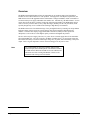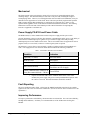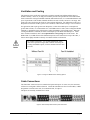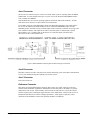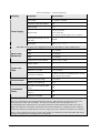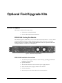
1
Ross Video Limited DFR-8104A(-C) Digital Products Frame & Power Supply (PS-8102) User Manual Ross Part Number: 8104ADR-004 Issue: 01A DFR-8104A(-C) • Digital Products Frame & Power Supply (PS-8102) User Manual • • • Ross Part Number: 8104ADR-004 Document Issue: 01A Release Date: November 30, 2005. Printed in Canada. The information contained in this User Manual is subject to change without notice or obligation. Copyright © 2005 Ross Video Limited. All rights reserved. Contents of this publication may not be reproduced in any form without the written permission of Ross Video Limited. Reproduction or reverse engineering of copyrighted software is prohibited. Notice The material in this manual is furnished for informational use only. It is subject to change without notice and should not be construed as a commitment by Ross Video Limited. Ross Video Limited assumes no responsibility or liability for errors or inaccuracies that may appear in this manual. Trademarks • • • is a registered trademark of Ross Video Limited. and MLE are registered trademarks of Ross Video Limited. Ross, ROSS, All other product names and any registered and unregistered trademarks mentioned in this manual are used for identification purposes only and remain the exclusive property of their respective owners. ROSS , Important Regulatory and Safety Notices Before using this product and any associated equipment, refer to the “Important Safety Instructions” listed below so as to avoid personnel injury and to prevent product damage. Products may require specific equipment, and /or installation procedures be carried out to satisfy certain regulatory compliance requirements. Notices have been included in this publication to call attention to these Specific requirements. Symbol Meanings This symbol on the equipment refers you to important operating and maintenance (servicing) instructions within the Product Manual Documentation. Failure to heed this information may present a major risk of damage or injury to persons or equipment. Warning Caution Notice The symbol with the word “Warning” within the equipment manual indicates a potentially hazardous situation, which if not avoided, could result in death or serious injury. The symbol with the word “Caution” within the equipment manual indicates a potentially hazardous situation, which if not avoided, may result in minor or moderate injury. It may also be used to alert against unsafe practices. The symbol with the word “Notice” within the equipment manual indicates a situation, which if not avoided, may result in major or minor equipment damage or a situation which could place the equipment in a non-compliant operating state. This symbol is intended to alert the user to the presence of uninsulated "dangerous voltage" within the product enclosure that may be of sufficient magnitude to constitute a risk of shock to persons. Warning Hazardous Voltages This symbol is used to alert the user that an electrical or electronic device or assembly is susceptible to damage from an ESD event. ESD Susceptibility Important Safety Instructions Warning Warning Warning Warning Read these instructions. Keep these instructions. Heed all warnings. Follow all instructions. The safe operation of this product requires that a protective earth connection be provided. A grounding conductor in the equipment's supply cord provides this protective earth. To reduce the risk of electrical shock to the operator and service personnel, this ground conductor must be connected to an earthed ground. Use only power cords specified for this product and certified for the country of use. Refer to the Product Power Cord Requirement Section that follows. Do not defeat the safety purpose of the grounding-type plug. A grounding type plug has two blades and a third grounding prong. The third prong is provided for your safety. If the provided plug does not fit in to your outlet, consult an electrician for replacement of the obsolete outlet. Protect the power cord from being walked on or pinching particularly at plugs, convenience receptacles, and point where they exit from the apparatus. Indoor Use: “WARNING – TO REDUCE THE RISK OF FIRE OR ELECTRIC SHOCK, DO NOT EXPOSE THIS APPERATUS TO RAIN OR MOISTURE” Do not use this apparatus near water. Do not block any ventilation openings. Install in accordance with manufacturer’s instructions. Do not install near heat sources such as radiators, heat registers, stoves, or other apparatus (including amplifiers) that produce heat. Only use attachments/accessories specified by the manufacturer. Unplug this apparatus during lightning storms or when unused for long periods of time. Clean only with a dry cloth. Refer all servicing to qualified personnel. Servicing is required when the apparatus has been damaged in any way, such as power-supply cord or plug damage, liquid has been spilled or objects have fallen into the apparatus, the apparatus has been exposed to rain or moisture, does not operate normally, or has been dropped. Certain parts of this equipment still present a safety hazard, with the power switch in the OFF position. To avoid electrical shock, disconnect all A/C power cords from the chassis' rear appliance connectors before servicing. To reduce the risk of fire, replacement fuses must be the same type and rating. Caution Caution Warning Service barriers within this product are intended to protect the operator and service personnel from hazardous voltages. For continued safety, replace all barriers after servicing. This product contains safety critical parts, which if incorrectly replaced may present a risk of fire or electrical shock. Components contained within the product’s power supplies and power supply area, are not intended to be customer serviced and should be returned to the factory for repair. Product Power Cord Requirements Warning Warning North American Line Voltages 100 - 120 Volts This product is supplied with certified 10A/125V SVT type supply cords. Conductors are color coded white (neutral), black (line) and green or green/yellow (ground). Operation of this equipment at line voltages exceeding 130V requires that alternative supply cords with appropriate voltage and current ratings be used International Line Voltages 200 - 240 Volts This product has been designed for use with certified IEC 320- C13 10A/250V H03 VV-F3G 1.00mm2 type line cord. International product orders are supplied with a certified 10A/250V line cords, utilizing a molded 3-pin IEC 320-C13 type connector at one end and stripped conductors on the other. One line cord is provided. Conductors are CEE color coded; blue (neutral), brown (line), and green/yellow (ground). Installation by a qualified Electrician, of an appropriately approved A/C wall plug certified for the country of use, is required. Alternatively, other IEC 320 C-13 type power cords may be used, provided that they meet the necessary safety certification requirements for the country in which they are to be used. Refer to the correctly specified line cord above. EMC Notices US FCC Part 15 This equipment has been tested and found to comply with the limits for a class A Digital device, pursuant to part 15 of the FCC Rules. These limits are designed to provide reasonable protection against harmful interference when the equipment is operated in a commercial environment. This equipment generates, uses, and can radiate radio frequency energy and, if not installed and used in accordance with the instruction manual, may cause harmful interference to radio communications. Operation of this equipment in a residential area is likely to cause harmful interference in which case users will be required to correct the interference at their own expense. Changes or modifications to this equipment not expressly approved by Ross Video Ltd. could void the user’s authority to operate this equipment. Notice CANADA This Class “A” digital apparatus complies with Canadian ICES-003. Cet appareil numerique de classe “A” est conforme à la norme NMB-003 du Canada. EUROPE This equipment is in compliance with the essential requirements and other relevant provisions of CE Directive 93/68/EEC. INTERNATIONAL This equipment has been tested to CISPR 22:1997 along with amendments A1:2000 and A2:2002 and found to comply with the limits for a Class A Digital device. This is a Class A product. In domestic environments this product may cause radio interference in which case the user may have to take adequate measures. Notice Maintenance/User Serviceable Parts Routine maintenance to this RossGear product is not required. This product contains no user serviceable parts. If the module does not appear to be working properly, please contact Technical Support using the numbers listed under the “Contact Us” section on the last page of this manual. All RossGear products are covered by a generous 5-year warranty and will be repaired without charge for materials or labor within this period. See the “Warranty and Repair Policy” section in this manual for details. Environmental Information The equipment that you purchased required the extraction and use of natural resources for its production. It may contain hazardous substances that could impact health and the environment. To avoid the potential release of those substances into the environment and to diminish the need for the extraction of natural resources, Ross Video encourages you to use the appropriate take-back systems. These systems will reuse or recycle most of the materials from your end-of-life equipment in an environmentally friendly and health conscious manner. The crossed-out wheeled bin symbol invites you to use these systems. If you need more information on the collection, reuse, and recycling systems, please contact your local or regional waste administration. You can also contact Ross Video for more information on the environmental performances of our products. Contents Introduction 1-1 In This Chapter .......................................................................................................................1-1 A Word of Thanks....................................................................................................1-1 Overview ..................................................................................................................1-2 Features ....................................................................................................................1-3 Documentation Terms ..............................................................................................1-3 Installation and Setup 2-1 In This Chapter .......................................................................................................................2-1 Static Discharge........................................................................................................2-1 Unpacking ................................................................................................................2-1 Mechanical ...............................................................................................................2-2 Power Supply PS-8102 and Power Cable ................................................................2-2 Fault Reporting.........................................................................................................2-2 Improving Performance............................................................................................2-2 Ventilation and Cooling ...........................................................................................2-3 Cable Connections....................................................................................................2-3 Specifications 3-1 In This Chapter .......................................................................................................................3-1 Technical Specifications...........................................................................................3-1 Optional Field Upgrade Kits 4-1 In this Chapter ........................................................................................................................4-1 CFM-8104A Cooling Fan Module ...........................................................................4-1 FSB-7110 Rear Support Bars and Brackets .............................................................4-2 Service Information 5-1 In This Chapter .......................................................................................................................5-1 Troubleshooting Checklist .......................................................................................5-1 Warranty and Repair Policy .....................................................................................5-2 Ordering Information 6-1 In This Chapter .......................................................................................................................6-1 DFR-8104A(-C) and Related Products ....................................................................6-1 DFR-8104A User Manual (Iss. 01A) Contents • i Introduction In This Chapter This chapter contains the following information sections: • A Word of Thanks • Overview • Features • Documentation Terms A Word of Thanks Congratulations on choosing the Ross Video DFR-8104A(-C) Digital Products Frame & Power Supply (PS-8102). The DFR-8104A(-C) is part of a full line of Digital Products within the RossGear Terminal Equipment family of products, backed by Ross Video’s experience in engineering and design expertise since 1974. You will be pleased at how easily your new DFR-8104A(-C) fits into your overall working environment. Equally pleasing is the product quality, reliability and functionality. Thank you for joining the group of worldwide satisfied Ross Video customers! Should you have a question pertaining to the installation or operation of your DFR-8104A(-C), please contact us at the numbers listed on the back cover of this manual. Our technical support staff is always available for consultation, training, or service. DFR-8104A User Manual (Iss. 01A) Introduction • 1-1 Overview The DFR-8104A Digital Products Frame accommodates up to four Ross 8000 series Distribution Products or four Leitch* 6800 series video products. For high power consumption requirements, the DFR-8104A can be field upgraded with the CFM-8104A Cooling Fan Module, which is mounted in a slot between the power supply and module slot number four. Alternatively, the DFR-8104A-C version comes direct from the factory with the cooling fan option already installed. The DFR-8104A design offers several key features such as; heavy-duty door hinges, durable powder-coat paint finish, and a specially designed top cover to enable frame stacking in high density environments. The DFR-8104A carries forward the heritage of our past digital frames by featuring our unique Master Reference Input, which accepts one external analog color black signal that is distributed to all modules. The frame also employs rugged aluminum construction, which provides superb heat dissipation, as well as the use of the highest quality connectors throughout the product. The new universal power supply, PS-8102, is a power factor corrected supply that will accommodate all world standards (85 - 250 volts) with up to 80 Watts of module power. Of special note is that the PS-8102 has the ability to sustain a 100ms input voltage loss, or glitch, while maintaining a full power output. This is of great importance in areas where incoming power may not be clean. Note It is recommended, for long-term reliability and increased product lifespan, that total dissipation of all modules installed in a DFR-8104A 1RU frame should not exceed 16 Watts total without the use of the Cooling Fan Module. Please see the Ventilation and Cooling section for details. * Leitch is a trademark of Leitch Technology Corporation 1-2 • Introduction DFR-8104A User Manual (Iss. 01A) Features The following features make the DFR-8104A(-C) one of the finest digital products frames on the market today:: • DFR-8104A (& DFR-8104A-C) accommodates 4 modules in 1 rack unit • Heavy duty door hinges • Durable powder-coat paint finish • Aluminum construction for increased heat dissipation and weight reduction • Master Reference Input feeds all module slots • Power Switch is accessible from front of the rack frame • Universal Power Supply (PS-8102) for all world standards (85 - 264 volts) • PS-8102 sustains a 100ms incoming power glitch while maintaining full output power • Power factor corrected supply with power fail detection circuit • PowerLock cord retainer mechanism guards against accidental power loss • Optional Cooling Fan Module for increased ventilation • Fan Fail and Error Indicator LED's on front of the frame (available with optional Cooling Fan Module) • Optional Extender Board Module for servicing • Optional Cable Support Bracket • Optional Frame Support Brackets • 5-year transferable warranty • Also accepts Leitch 6800 series video products Documentation Terms The following terms are used throughout this guide: • “Frame” refers to the DFR-8104A(-C) frames that house the cards. • All references to the DFR-8104A also include the DFR-8104A-C version with the cooling fan option. See the appropriate section in this User Manual for details. • “Operator” and “User” both refer to the person who uses the DFR-8104A. • “Board”, “Card”, and “Module” all refer to the RossGear card(s) installed in the frame, including all components and switches. • “System” and “Video system” refers to the mix of interconnected digital and analog production and terminal equipment in which the DFR-8104A operates. DFR-8104A User Manual (Iss. 01A) Introduction • 1-3 1-4 • Introduction DFR-8104A User Manual (Iss. 01A) Installation and Setup In This Chapter This chapter contains the following information sections: • Static Discharge • Unpacking • Mechanical • Power Supply PS-8102 and Power Cable • Fault Reporting • Improving Performance • Ventilation and Cooling • Cable Connections • Module Slot Reference Chart Static Discharge Whenever handling the DFR-8104A(-C) and other related equipment, please observe all static discharge precautions as described in the following note: ESD Susceptibility Static discharge can cause serious damage to sensitive semiconductor devices. Avoid handling circuit boards in high static environments such as carpeted areas, and when wearing synthetic fiber clothing. Always exercise proper grounding precautions when working on circuit boards and related equipment. Unpacking Unpack each DFR-8104A(-C) you received from the shipping container, and check the contents against the packing list to ensure that all items are included. If any items are missing or damaged, contact your sales representative or Ross Video directly. DFR-8104A User Manual (Iss. 01A) Installation and Setup • 2-1 Mechanical The frame mounts in the rack cabinet by means of four rack screws fastened through the front mounting flanges. This should normally be sufficient to carry the load, including the weight of accompanying cables. However, in certain applications such as mobile truck installations, it may be desirable to also support the rear of the frame. Ross Video has specifically engineered the optional FSB-7110 Rear Support Bars and Brackets to compensate for extra load stress. Please see the Optional Field Upgrades section of this manual for detailed installation instructions. The Ordering Information section at the end of this manual provides contact information for acquiring this innovative equipment at a nominal cost. Power Supply PS-8102 and Power Cable The DFR-8104A(-C) comes standard with one PS-8102 power supply and one power cable. Of great importance to the user who may have unstable or unpredictable facility power, is the ability of the PS-8102 to withstand input power glitches of up to 100ms in length, while still providing uninterrupted power to the modules in the frame. This is an essential feature for applications such as program feeds, live event feeds, or wherever a robust signal system is required. The PS-8102 is a power factor corrected supply, capable of working with all world standards (85 250V). The supply has an error detection circuit that will indicate the following conditions: Table 1. PS-8102 Error Detection Circuit Conditions Condition Indication Light load (< 2 Watts) Red LED flashes Blown O/P fuse Red LED lit Short circuit (internal)* Red LED flashes Short circuit (external) Red LED lit Fuse blows on O/P of supply Normal conditions load: 2 Watts to 40 Watts (Recommended load > 2 Watts) Green LED lit * If power is turned on with a "short" condition in the frame or one of the modules, the power supply will go into a startup and shutdown sequence until the "short" is removed. The Red LED flashes under this condition. Fault Reporting The error conditions listed in Table 1 will trigger the SMPTE 269M fault reporting circuit, and the signal will be sent to Aux A on the back of the frame. (See the section on Aux A Connector for a full explanation.) Improving Performance To improve performance and reliability, the PS-8102 has an on-board fan. For even better reliability, and high load conditions (>16 Watts), we recommend the use of the CFM-8104A Cooling Fan Module. 2-2 • Installation and Setup DFR-8104A User Manual (Iss. 01A) Ventilation and Cooling This frame has been specifically engineered to minimize internal heat buildup and thus improve module reliability. However, for long-term reliability and increased product life of the DFR-8104A frame (without the Cooling Fan Module installed) and installed cards, it is recommended that the total power requirements of all modules installed should not exceed 16 Watts, and to leave an empty 1RU panel space above and below the frame for improved heat dissipation. For information on the power dissipation of RossGear modules, please refer to the Ross Video Product Catalog or visit our website. For applications that require greater heat dissipation, or where the module power consumption is greater than 16 Watts, we recommend the use of the DFR-8104A-C frame (with Cooling Fan Module installed), or installation of the CFM-8104A Cooling Fan Module, field upgrade option. When the Cooling Fan Module is installed, the frame can dissipate up to 40 Watts of module power. Under these ventilated conditions, there is no requirement for extra spacing between the frames. The DFR-8104A-C (or DFR-8104A with CFM-8104A option) can be stacked one on top of the other, a feature that is highly desirable in densely crowded rack frame environments. Notice For reliable performance, it is recommended that the frame door not be opened for longer than 5 minutes when using the Cooling Fan Module option, on frames loaded with more than 16 watts. Figure 1. Cooling Fan Module Frame Stacking Options Cable Connections The frame BNC connectors have been marked as inputs and outputs. In some cases, the connectors will have been assigned a different function. Consult the installation section of each module, or BNC designations screened on the card, for a translation table, if required. The inputs are internally terminated in 75 ohms. Figure 2. DFR-8104A (& DFR-8104A-C) Rear Panel View DFR-8104A User Manual (Iss. 01A) Installation and Setup • 2-3 Aux A Connector The Aux A telco connector may be wired to an external alarm system for reporting alarms in SMPTE 269M format. For more details on this type of system, refer to the document ANSI/SMPTE 269M 1994, available from SMPTE. Some modules have provision for reporting signal loss and certain other fault conditions. All such cards in the frame connect to an opto-isolator circuit in the frame. For example, in the case of the SRA-8001A Serial Auto-Reclocking Amplifier, if the input signal is lost or low, the INPUT STATUS Red LED will be lit. If the FAULT REPORT jumper is in the ENABLE position, then there will be a pulsed contact closure on the telco connector for as long as the error condition continues. The output circuit will be closed for about 1-2 milliseconds, repeated approximately every 17 milliseconds. In the absence of a fault, the output will remain open. The circuit can drive a 20mA alarm load. Figure 3. SMPTE 269M Alarm Reporting Internal interface and typical connections Aux B Connector This BNC connector is used to relay data to an external monitoring system. Serial data communication is used. Only modules having this capability will use this system. Aux C Connector Reserved for future use. Reference Connector This feature, developed and brought to market by Ross Video, uses a BNC connector to input an external master frame REF signal that is distributed across the back plane to all modules. Typically analog black video is used. Some modules, which need an external reference, can use this "master" reference signal in place of taking the signal from one of the module BNC. This provides for ease of installation and reduction in reference cabling requirements. If this signal is required, it will be mentioned in the Installation section of the particular module's User Manual. 2-4 • Installation and Setup DFR-8104A User Manual (Iss. 01A) Specifications In This Chapter This chapter contains the Technical Specifications table. Technical Specifications DFR-8104A User Manual (Iss. 01A) Specifications • 3-1 Table 2. DFR-8104A(-C) - Technical Specifications Category Power Supply Parameter Specification Input Voltage 85 - 250VAC 50/60 Hz Input Power (1RU DFR-8104A) 75W Output Voltage 6.7V Output Current +6.7V @ 13A max -6.7V @ 4A max Note: the sum of both outputs not to exceed 9A. Line Regulation change over full input range <250mV Output ripple <60mV p-p (1.8%) For safety reasons, Ross power supplies do not fit into rack frames of other manufacturers. Rack Frame Mechanical Frame Card Slots Environmental Total Module Power Height 1.75" (45mm) Width 19" (483mm) Depth 13" (330mm) Weight, with 10 cards installed: approx. 7.9lbs. (3.58kg) Number of Slots 10 Max Power: +12V Rail 1.0A (12 Watts) Max Power: -7.5V Rail 0.2A (1.5 Watts) Total Frame Card Power 120 Watts, total power consumption not to exceed 12W maximum per card slot. Ambient temperature range 0 ºC to 40 ºC Humidity, non condensing <95% 1RU Frame non-ventilated (DFR8104A) 16W 1RU Frame ventilated (DFR8104A-C) 40W Output power available 80W Important Notes: The power requirement of each product installed in this frame is indicated in the Specifications section of the documentation provided with each module. For long-term reliability and increased product life, it is recommended that the total dissipation of all modules installed in a DFR-8104A frame should not exceed 16 Watts total without the CFM-8104A, and 40 Watts total with the CFM-8104A. In addition, frames without the CFM-8104A should be provided with one rack unit of empty space above and below each frame for ventilation. Please see the Ventilation and Cooling section in this product's User Manual for further information and options for higher load applications requiring greater heat dissipation. 3-2 • Specifications DFR-8104A User Manual (Iss. 01A) Optional Field Upgrade Kits In this Chapter This chapter contains the following sections: • CFM-8104A Cooling Fan Module • FSB-7110 Rear Support Bars and Brackets CFM-8104A Cooling Fan Module The standard equipment, DFR-8104A, can be also be ordered as the DFR-8104A-C version, with the Cooling Fan Module installed as original equipment from the factory. However, for customers wishing to increase the ventilation on their standard DFR-8104A frames, the optional CFM-8104A Cooling Fan Module is available as a field upgrade kit. Figure 4. CFM-8104A Cooling Fan Module CFM-8104A Installation Instructions 1. Turn off the power supply and observe static electricity grounding precautions for handling electronic devices. 2. Open the frame door. 3. Slide the fan board into the slot between the power supply and slot 4. 4. Ensure that the board is properly seated into the connector. 5. Close the frame door. 6. Reconnect power to the frame and check for normal operation. DFR-8104A User Manual (Iss. 01A) Optional Field Upgrade Kits • 4-1 FSB-7110 Rear Support Bars and Brackets† Under normal conditions, mounting the frame to the front of the rack with the four rack screws provided, should be sufficient to carry the load, including the weight of accompanying cables. However, Ross Video has specifically engineered the optional FSB-7110 Rear Support Bars and Brackets to compensate for extra load stress associated with certain applications, such as mobile truck installations, to also support the rear of the frame. Figure 5. FSB-7110 Rear Support Bars and Brackets Diagram FSB-7110 Installation Instructions 1. The rear support bars can be attached to the Ross frame in six possible positions; see Figure 5. Choose the position that suits the cabinet depth and will give approximately ½ inch projection beyond the rear vertical mounting rails. Using four screws per bar, as shown in Figure 5, fasten one bar to each side of the Ross frame. 2. Mount the Ross frame to the front rails of the rack cabinet using four rack screws fastened through the front mounting flanges. 3. At the rear of the cabinet, slide the bracket slots over the rear of the support bars and secure to the cabinet rear rails with two rack screws each. † Please note that the FSB-7110 and CSB-8100 can not be installed on the same frame unit. 4-2 • Optional Field Upgrade Kits DFR-8104A User Manual (Iss. 01A) Service Information In This Chapter This chapter contains the following sections: • Troubleshooting Checklist • Warranty and Repair Policy Troubleshooting Checklist Routine maintenance to this RossGear product is not required. In the event of problems with your DFR-8104A(-C), the following basic troubleshooting checklist may help identify the source of the problem. If the module still does not appear to be working properly after checking all possible causes, please contact your Ross Video products distributor, or the Ross Video Technical Support department at the numbers listed under the “Contact Us” section at the end of this manual. 1. Visual Review – Performing a quick visual check may reveal many problems, such as connectors not properly seated or loose cables. Check the module, the frame, and any associated peripheral equipment for signs of trouble. 2. Power Check – Check the power indicator LED on the distribution frame front panel for the presence of power. If the power LED is not illuminated, verify that the power cable is connected to a power source and that power is available at the power main. Confirm that the power supplies are fully seated in their slots. If the power LED is still not illuminated, replace the power supply with one that is verified to work. 3. Input Signal Status – Verify that source equipment is operating correctly and that a valid signal is being supplied. 4. Output Signal Path – Verify that destination equipment is operating correctly and receiving a valid signal. 5. Unit Exchange – Exchanging a suspect unit with a unit that is known to be working correctly is an efficient method for localizing problems to individual units. DFR-8104A User Manual (Iss. 01A) Service Information • 5-1 Warranty and Repair Policy The RossGear DFR-8104A(-C) is warranted to be free of any defect with respect to performance, quality, reliability, and workmanship for a period of FIVE (5) years from the date of shipment from our factory. In the event that your RossGear DFR-8104A(-C) proves to be defective in any way during this warranty period, Ross Video Limited reserves the right to repair or replace this piece of equipment with a unit of equal or superior performance characteristics. Should you find that this RossGear DFR-8104A(-C) has failed after your warranty period has expired, we will repair your defective product should suitable replacement components be available. You, the owner, will bear any labor and/or part costs incurred in the repair or refurbishment of said equipment beyond the FIVE (5) year warranty period. In no event shall Ross Video Limited be liable for direct, indirect, special, incidental, or consequential damages (including loss of profits) incurred by the use of this product. Implied warranties are expressly limited to the duration of this warranty. This RossGear DFR-8104A(-C) User Manual provides all pertinent information for the safe installation and operation of your RossGear Product. Ross Video policy dictates that all repairs to the RossGear DFR-8104A(-C) are to be conducted only by an authorized Ross Video Limited factory representative. Therefore, any unauthorized attempt to repair this product, by anyone other than an authorized Ross Video Limited factory representative, will automatically void the warranty. Please contact Ross Video Technical Support for more information. In Case of Problems Should any problem arise with your RossGear DFR-8104A(-C), please contact the Ross Video Technical Support Department. (Contact information is supplied at the end of this publication.) A Return Material Authorization number (RMA) will be issued to you, as well as specific shipping instructions, should you wish our factory to repair your RossGear DFR-8104A(-C). If required, a temporary replacement module will be made available at a nominal charge. Any shipping costs incurred will be the responsibility of you, the customer. All products shipped to you from Ross Video Limited will be shipped collect. The Ross Video Technical Support Department will continue to provide advice on any product manufactured by Ross Video Limited, beyond the warranty period without charge, for the life of the equipment. 5-2 • Service Information DFR-8104A User Manual (Iss. 01A) Ordering Information In This Chapter This chapter contains ordering information for the DFR-8104A(-C) and related products. DFR-8104A(-C) and Related Products Standard Equipment • DFR-8104A Digital Products Frame and Power Supply (PS-8102) (1RU, holds 4 modules, includes 1 power supply) • 8104ADR-004 Digital Products Frame & Power Supply (PS-8102) User Manual Optional Equipment • 8104ADR-004 Digital Products Frame & Power Supply (PS-8102) User Manual (additional User Manual) • DFR-8104A-C Digital Products Frame with Cooling Fan Module and Power Supply (PS-8102) (1RU, holds 4 modules, includes 1 power supply) • CFM-8104A Cooling Fan Module (upgrade cooling kit for standard DFR-8104A(-C)) • PS-8102 Power Supply (85-264 Volts) (redundancy option power supply for Ross 8000 series 2RU digital product frames) • FSB-7110 Rear Support Bars and Brackets (additional support for rear frame-to-rack mounting) • EXT-8100 Extender Board (module servicing extension) Your DFR-8104A(-C) Digital Products Frame & Power Supply (PS-8102) is a part of the RossGear family of products. Ross Video offers a full line of RossGear terminal equipment including distribution, conversion, monitoring, synchronizers, encoders, decoders, keyers, switches, as well as analog audio and video products. DFR-8104A User Manual (Iss. 01A) Ordering Information • 6-1 Contact Us Contact our friendly and professional support representatives for the following: • Name and address of your local dealer • Product information and pricing • Technical support • Upcoming trade show information PHONE E-MAIL POSTAL SERVICE General Business Office and Technical Support 613 • 652 • 4886 After-hours Emergency 613 • 652 • 4886 ext. 333 Fax 613 • 652 • 4425 General Information [email protected] Technical Support [email protected] Ross Video Limited 8 John Street, Iroquois, Ontario, Canada K0E 1K0 Ross Video Incorporated P.O. Box 880, Ogdensburg, New York, USA 13669-0880 Visit Us Please visit us at our website for: • Company information • Related products and full product lines • On-line catalog • Trade show information • News • Testimonials