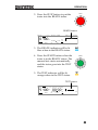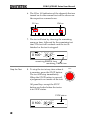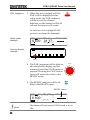
1
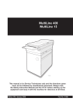
Multiplex Scanner Box GSB-01/GSB-02 USER MANUAL GW INSTEK PART NO. 82SB-02000EA1 ISO-9001 CERTIFIED MANUFACTURER This manual contains proprietary information, which is protected by copyright. All rights are reserved. No part of this manual may be photocopied, reproduced or translated to another language without prior written consent of Good Will company. The information in this manual was correct at the time of printing. However, Good Will continues to improve products and reserves the rights to change specification, equipment, and maintenance procedures at any time without notice. Good Will Instrument Co., Ltd. No. 7-1, Jhongsing Rd., Tucheng Dist., New Taipei City 236, Taiwan. Table of Contents Table of Contents SAFETY INSTRUCTIONS ................................................... 4 GETTING STARTED ........................................................... 9 GSB-01 and GSB-02 Overview .............. 10 Appearance .......................................... 13 Safety Considerations .......................... 18 OPERATION .................................................................... 23 Menu Tree Additions ............................ 24 Test Lead Connection ........................... 25 Start Up Procedure .............................. 35 Creating a Test Setup ........................... 37 Automatic Tests ................................... 51 Common Utility Settings ...................... 63 REMOTE CONTROL ........................................................ 65 FAQ ................................................................................ 71 APPENDIX ...................................................................... 73 Fuse Replacement ................................ 73 Error Messages .................................... 74 Specifications ...................................... 75 Dimensions ......................................... 76 Declaration of Conformity .................... 78 INDEX............................................................................. 79 3 SAFETY INSTRUCTIONS SAFETY INSTRUCTIONS This chapter contains important safety instructions that you must follow during operation and storage. Read the following before any operation to ensure your safety and to keep the instrument in the best possible condition. Safety Symbols These safety symbols may appear in this manual or on the instrument. WARNING Warning: Identifies conditions or practices that could result in injury or loss of life. CAUTION Caution: Identifies conditions or practices that could result in damage to the instrument or to other properties. DANGER High Voltage Attention Refer to the Manual Protective Conductor Terminal Frame or Chassis Terminal Earth (ground) Terminal 4 SAFETY INSTRUCTIONS Do not dispose electronic equipment as unsorted municipal waste. Please use a separate collection facility or contact the supplier from which this instrument was purchased. Safety Guidelines General Guideline CAUTION Do not place any heavy object on the instrument. Avoid severe impact or rough handling that leads to damaging the instrument. Do not discharge static electricity to the instrument. Use only mating connectors, not bare wires, for the terminals. Do not block the cooling fan opening. Do not disassemble the GSB-01/GSB-02 unless you are qualified. (Measurement categories) EN 61010-1:2010 specifies the measurement categories and their requirements as follows. The GSB-01/GSB-02 falls under category II. Measurement category IV is for measurement performed at the source of low-voltage installation. Measurement category III is for measurement performed in the building installation. Measurement category II is for measurement performed on the circuits directly connected to the low voltage installation. Power Supply WARNING AC Input voltage range: 100 - 240VAC ±10% Frequency: 50Hz/60Hz To avoid electrical shock connect the protective grounding conductor of the AC power cord to an earth ground. 5 GSB-01/GSB-02 Series User Manual Fuse WARNING Cleaning the GSB-01/GSB-02 Operation Environment Fuse Type: T 2A/250V To ensure fire protection, replace the fuse only with them specified type and rating. Disconnect the power cord before replacing the fuse. Make sure the cause of the fuse blowout is fixed before replacing the fuse. Disconnect the power cord before cleaning. Use a soft cloth dampened in a solution of mild detergent and water. Do not spray any liquid. Do not use chemicals containing harsh material such as benzene, toluene, xylene, and acetone. Location: Indoor, no direct sunlight, dust free, almost non-conductive pollution (Note below) Relative Humidity: ≤ 70% (no condensation) Altitude: < 2000m Temperature: 0˚C~40˚C (Pollution Degree) EN 61010-1:2010 specifies the pollution degrees and their requirements as follows. The GSB-01/GSB-02 falls under degree 2. Pollution refers to “addition of foreign matter, solid, liquid, or gaseous (ionized gases), that may produce a reduction of dielectric strength or surface resistivity”. Pollution degree 1: No pollution or only dry, non-conductive pollution occurs. The pollution has no influence. Pollution degree 2: Normally only non-conductive pollution occurs. Occasionally, however, a temporary conductivity caused by condensation must be expected. Pollution degree 3: Conductive pollution occurs, or dry, nonconductive pollution occurs which becomes conductive due to condensation which is expected. In such conditions, equipment is normally protected against exposure to direct sunlight, precipitation, and full wind pressure, but neither temperature nor humidity is controlled. 6 SAFETY INSTRUCTIONS Storage environment Disposal Location: Indoor Temperature: -10°C to 70°C Relative Humidity: ≤ 85% (no condensation) Do not dispose this instrument as unsorted municipal waste. Please use a separate collection facility or contact the supplier from which this instrument was purchased. Please make sure discarded electrical waste is properly recycled to reduce environmental impact. 7 GSB-01/GSB-02 Series User Manual Power cord for the United Kingdom When using the scanner box in the United Kingdom, make sure the power cord meets the following safety instructions. NOTE: This lead/appliance must only be wired by competent persons WARNING: THIS APPLIANCE MUST BE EARTHED IMPORTANT: The wires in this lead are coloured in accordance with the following code: Green/ Yellow: Earth Blue: Neutral Brown: Live (Phase) As the colours of the wires in main leads may not correspond with the coloured marking identified in your plug/appliance, proceed as follows: The wire which is coloured Green & Yellow must be connected to the Earth terminal marked with either the letter E, the earth symbol or coloured Green/Green & Yellow. The wire which is coloured Blue must be connected to the terminal which is marked with the letter N or coloured Blue or Black. The wire which is coloured Brown must be connected to the terminal marked with the letter L or P or coloured Brown or Red. If in doubt, consult the instructions provided with the equipment or contact the supplier. This cable/appliance should be protected by a suitably rated and approved HBC mains fuse: refer to the rating information on the equipment and/or user instructions for details. As a guide, a cable of 0.75mm2 should be protected by a 3A or 5A fuse. Larger conductors would normally require 13A types, depending on the connection method used. Any exposed wiring from a cable, plug or connection that is engaged in a live socket is extremely hazardous. If a cable or plug is deemed hazardous, turn off the mains power and remove the cable, any fuses and fuse assemblies. All hazardous wiring must be immediately destroyed and replaced in accordance to the above standard. 8 GETTING STARTED GETTING STARTED This chapter describes the scanner box in a nutshell, including its main features and front / rear panel introduction. After going through the overview, please read the safety considerations. CAUTION 5.0 kVAC MAX. 6.0 kVDC MAX. HIGH VOLTAGE GSB-01 CHANNEL POWER Multiplex Scanner Box HI HI HI HI HI HI HI HI LO LO LO LO LO LO LO LO 1 2 3 4 5 6 7 8 PASS FAIL RETURN GSB-01 and GSB-02 Overview .......................................... 10 Lineup ....................................................................................................... 10 Firmware Note ......................................................................................... 10 Model Overview ...................................................................................... 10 Main Features .......................................................................................... 11 Accessories and Package Contents ....................................................... 11 Appearance ..................................................................... 13 GSB-01 Front Panel ................................................................................. 13 GSB-02 Front Panel ................................................................................. 13 GSB-01 Rear Panel ................................................................................... 16 GSB-02 Rear Panel ................................................................................... 16 Safety Considerations ...................................................... 18 Workplace Precautions ........................................................................... 18 Operating Precautions ............................................................................ 20 Basic Safety Checks ................................................................................. 22 9 GSB-01/GSB-02 Series User Manual GSB-01 and GSB-02 Overview Lineup The aim of these scanner boxes is to allow multiple DUTs to be tested either concurrently or in sequence using the GPT-9800, GPT9900 or GPT-9900A safety testers. The scanner boxes are particularly well suited for multi-point safety testing as well for volume testing on factory floors. The GSB-01 has connections for ACW, DCW and IR testing, while the GSB-02 also includes support for GB testing. Firmware Note Please make sure the firmware is up to date before using the scanner boxes. Please see the user manual to check the firmware version. GPT-9800: firmware version V3.0 or above GPT-9900/9900A: firmware version V2.0 or above Note: Throughout this user manual, the terms scanner box or GSB will refer to either model (GSB-01, GSB-02) unless specifically stated otherwise. GPT-9000 will refer to any of the GPT-9800, GPT9900 or GPT-9900A safety testers, unless stated otherwise. HV and H will refer to High Voltage terminals, while LO and L will refer to the return terminal. Model Overview Model name ACW DCW IR GSB-01 GSB-02 10 GB Outputs 8 x HV 6 x HV, 2 x GB GETTING STARTED Main Features Performance Features Interface 8 HV outputs (6 for GSB-02) 2 GB outputs (GSB-02 only) ACW: 5kV AC DCW: 6kV DC IR: 1kV DC GB: 40A (GSB-02 only) PASS/FAIL LEDs HI LO LEDs Up to 4 scanner boxes can be connected RS-232 interface. Accessories and Package Contents Standard Accessories Part Number Description N/A GSB-01/02 unit N/A Quick start guide N/A User manual CD Region dependent Power cord GHT-108 x1 High voltage wiring leads GHT-109 x1 GB wiring leads (GSB-02 only) GHT-116R HV test leads for scanner box x8(GSB-01), x6(GSB-02) outputs GHT-116B x1 Return test lead for scanner box 11 GSB-01/GSB-02 Series User Manual Note 12 GTL-116R x2 GB sense/source H test lead (GSB-02 only) GTL-116B x1 GB sense/source L test lead (GSB-02 only) GTL-235 RS232C Cable Keep the packaging, including the box, polystyrene foam and plastic envelopes should the need arise to return the unit to GW Instek. GETTING STARTED Appearance GSB-01 Front Panel POWER Button HI / LO Indicators CAUTION 5.0 kVAC MAX. 6.0 kVDC MAX. HIGH VOLTAGE GSB-01 CHANNEL HIGH VOLTAGE Indicator Multiplex Scanner Box HI HI HI HI HI HI HI HI LO LO LO LO LO LO LO LO 1 2 3 4 5 6 7 8 PASS FAIL RETURN POWER Return Terminal Channel Pass/Fail Indicators GSB-02 Front Panel POWER Button HI / LO Indicators CAUTION 5.0 kVAC MAX. 6.0 kVDC MAX. HIGH VOLTAGE GSB-02 Multiplex Scanner Box HI HI HI HI HI HI HI HI LO LO LO LO LO LO LO LO 1 2 3 4 5 6 7 8 HI-POT IR RETURN CHANNEL PASS SENSE H SENSE L FAIL POWER GB Rx SOURCE H SOURCE L HIGH VOLTAGE Indicator Return Terminal/ SENSE L SOURCE L Channel Pass/Fail Indicators SENSE H SOURCE H 13 GSB-01/GSB-02 Series User Manual POWER switch POWER Turns the unit on or off. It is recommended that the unit is powered up before the connected safety tester is turned on. HI LO Indicators The HI/LO Indicators indicate whether a channel is set to the HI or LO output. If neither HI nor LO is lit, it indicates that that channel is disabled. Channel Indicators HIGH VOLTAGE output terminal The Channel Indicators will become lit green on a pass judgment or red on a fail judgment. CAUTION 5.0 kVAC MAX. 6.0 kVDC MAX. The HIGH VOLTAGE terminal output is used for outputting the testing voltage. The terminal is recessed for safety. This terminal is used in conjunction with the RETURN terminal. WARNING USE EXTREME CAUTION. Do not touch the HIGH VOLTAGE terminal during testing. RETURN terminal 14 RETURN The RETURN terminal is used for IR, DCW and ACW tests. GETTING STARTED RETURN, SENSE GSB-02 Only and SOURCE terminals SENSE H RETURN SENSE L GB Rx SOURCE H SOURCE L The RETURN terminal is used for IR, DCW and ACW tests. The SOURCE H, SOURCE L, SENSE H and SENSE L terminals are used for GB tests. 15 GSB-01/GSB-02 Series User Manual GSB-01 Rear Panel HV1 HV2 INPUT HV1 HV2 HIGH VOLTAGE CH1 CH1 CH3 CH3 OUTPUT HIGH VOLTAGE CH7 CH5 RS232/ RS232/ IN OUT CH7 RS232/IN 5.0 kVAC 6.0 kVDC MAX. SER. NO. LB 5.0 kVAC 6.0 kVDC MAX. CH5 RS232/OUT CH2 CH4 CH6 ENSURE THE POWER IS REMOVED FROM THE INSTRUMENT BEFORE REPLACING THE FUSE CH8 RETURN AC 100 50/60Hz 240V 50VA MAX. GND T 2A 250V Return CH2 CH4 CH6 CH8 GND Line voltage input & fuse GSB-02 Rear Panel HV1 HV2 INPUT HV1 HV2 HIGH VOLTAGE CH1 CH1 CH3 CH3 OUTPUT HIGH VOLTAGE CH7 RS232/ RS232/ IN OUT CH5 RS232/IN 5.0 kVAC 6.0 kVDC MAX. CH7 SER. NO. LB 5.0 kVAC 6.0 kVDC MAX. CH5 RS232/OUT HI-POT IR CH2 CH4 ENSURE THE POWER IS REMOVED FROM THE INSTRUMENT BEFORE REPLACING THE FUSE CH6 RETURN GB Rx SENSE H SENSE L SOURCE H SOURCE L CH8 AC 100 50/60Hz 240V 50VA MAX. GND SENSE H T 2A 250V SOURCE H SOURCE L CH2 Return/ SENSE L 16 CH4 CH6 CH8 GND Line voltage input & fuse GETTING STARTED HV1, HV2 The HV1 input terminal is used as the primary high voltage input for the scanner box. The HV2 output terminal is used to daisy chain the high voltage output to the next scanner when multiple scanner boxes are used together. CH1 ~ CH8 These channels are connected to the DUTs that are to be tested. The output state is configured from the GPT-9000 safety tester master. Note: For the GSB-02 CH7 and CH8 are used for ground bond testing only. RS232/IN RS232/OUT RS232/IN RS232/OUT These two RS232 interfaces are the communication links between the master (safety tester) to slave (scanner box). They are also used to connect multiple scanner boxes in a daisy chain. In addition the RS232/IN port is also used to perform firmware updates. Line voltage input: 100-240VAC, 50/60Hz. Line voltage input Line voltage fuse: Line voltage fuse T 2A 250V T 2A/250V GND GND Connect the GND (ground) terminal to the earth ground to ensure operational safety. 17 GSB-01/GSB-02 Series User Manual Safety Considerations Workplace Precautions Background WARNING The GPT-9000 is a high voltage instrument that outputs dangerous voltages. The following section describes precautions and procedures that must be followed to ensure a safe work environment when GSB-01/GSB-02 is connected to the GPT-9000 series safety testers. The GPT-9000 generates voltages in excess of 5kVAC or 6kVDC. Follow all safety precautions, warnings and directions given in the following section when using the instrument with the scanner boxes. 1. Only technically qualified personnel should be allowed to operate the safety tester and scanner box(es). 2. The operating workplace must be fully isolated, especially when the instrument is in operation. The instruments should be clearly labeled with appropriate warning signage. 3. The operator should not wear any conductive materials, jewelry, badges, or other items, such as wrist watches. 4. The operator should wear insulation gloves for high voltage protection. 5. Ensure the earth ground of the line voltage is properly grounded. 18 GETTING STARTED 6. Ensure any devices that are adversely affected by magnetic fields are not placed near the tester and scanner box(es). 19 GSB-01/GSB-02 Series User Manual Operating Precautions Background WARNING The GPT-9000 is a high voltage instrument that outputs dangerous voltages. The following section describes precautions and procedures that must be followed to ensure that the tester along with any conned scanner boxes are operated in a safe manner. The GPT-9000 generates voltages of up to 5kVAC or 6kVDC. Follow all safety precautions, warnings and directions given in the following section when using the instrument. 1. Never touch the safety tester, lead wires, terminals, probes, connected scanner box(es) or any other connected equipment when the tester is testing. 2. Do not turn the safety tester on and off quickly or repeatedly. When turning the power off, please allow a few moments before turning the power back on. This will allow the protection circuits to properly initialize. Do not turn the power off when a test is running, unless in an emergency. 3. Only use those test leads supplied with the instrument. Leads with inappropriate gauges can be dangerous to both the operator and the instrument. For GB testing, never use the Sense leads on the SOURCE terminals. 4. Do not short the HIGH VOLTAGE terminal with ground. Doing so could charge the chassis to dangerously high voltages. 20 GETTING STARTED 5. Ensure the earth ground of the line voltage is properly grounded. 6. Only connect the test leads to the HIGH VOLTAGE/SOURCE H/SENSE H terminals before the start of a test. Keep the test leads disconnected at all other times. 7. Always press the STOP button when pausing testing. 8. Do not leave the safety tester unattended. Always turn the power off when leaving the testing area. 9. When remotely controlling the safety tester, ensure adequate safety measures are in place to prevent: Inadvertent output of the test voltage. Accidental contact with the instrument during testing. Ensure that the instrument and DUT are fully isolated when the instrument is remotely controlled. 10. Ensure an adequate discharge time for the DUT. When DCW or IR tests are performed, the DUT, test leads and probes become highly charged. The GPT-9000 has discharge circuitry to discharge the DUT after each test. The time required for a DUT to discharge depends on the DUT and test voltage. Never disconnect the safety tester before a discharge is completed. 21 GSB-01/GSB-02 Series User Manual Basic Safety Checks Background The GSB-01/GSB-02 are used with high voltage devices and as such, daily safety checks should be made to ensure safe operation. 1. Ensure all test leads are not broken and are free from defects such as cracks or splitting. 2. Ensure the scanner box(es) are always connected to an earth ground. 3. Test the operation of the safety tester + scanner box(es) with a low voltage/current output: Ensure the safety tester generates a FAIL judgment when the HIGH VOLTAGE and RETURN terminals are shorted (using the lowest voltage/current as the testing parameters). WARNING 22 Do not use high voltages/currents when the HIGH VOLTAGE and RETURN terminals are shorted. It may result in damage to the instrument. OPERATION OPERATION Menu Tree Additions ....................................................... 24 Test Lead Connection ...................................................... 25 Connecting GSB-01 Units ....................................................................... 25 Connecting GSB-02 ................................................................................. 29 DUT Connection ...................................................................................... 32 Start Up Procedure .......................................................... 35 Startup....................................................................................................... 35 Connection Check ................................................................................... 36 Creating a Test Setup....................................................... 37 Scanner Box Test Creation Workflow................................................... 38 Select a Manual Test................................................................................ 38 Configure the Manual Test Settings ..................................................... 40 Configuring the Scanner Box Outputs ................................................. 41 Running a Manual Test .......................................................................... 44 MANU Test Results ................................................................................ 48 Automatic Tests .............................................................. 51 Create an Automatic Test ....................................................................... 51 Running an Automatic Test ................................................................... 54 Automatic Test Results ........................................................................... 58 23 GSB-01/GSB-02 Series User Manual Menu Tree Additions When the scanner boxes are added to the GPT-9000 safety tester the scan utility and the scanner configuration menu become available. These additional menu functions are highlighted in the menu tree below. PASS/FAIL result Special manual mode TEST Press S TOP status STOP status Press Press Press STOP2 START STOP READY MANU no. # 0003 status Switch to MANU mode Press Press MANU/ STOP AUTO Press PAGE View (AUTO mode only)1 PAGE Hold MANU/ V I EW Press status UTILITY AUTO Press EDIT/ Switch to AUTO mode MANU UTILITY menu (MANU mode only)1 SAVE Press Press ESC ESC Press ED I T UTILITY status Common Utility Settings1 Press SCAN Scan for connected scanner boxes Press PAGE Save the SCAN configuration Press EDIT/ SAVE Press Press PAGE ESC SCAN Configuration (MANU mode only)1 1 Press EDIT/SAVE to save settings, or ESC to cancel and return to the previous screen. 2 Press the STOP key twice for a FAIL result. 3 When in MANU mode, selecting MANU number 000 will enter the special manual mode. 4 The Sweep mode function is only accessible in the special manual mode. 24 PAGE View (AUTO mode only)1 OPERATION Test Lead Connection This section describes how to connect the GPT-9000 to a number of scanner boxes. It is recommended that only models of the same type are connected together. Connecting GSB-01 Units Background The following will describe how to connect scanner boxes to a GPT-9000 safety tester. Up to 4 scanner boxes can be connected. When wiring the scanner boxes to the safety tester or to each other, only the HV wiring leads (GHT-108) should be used. When connected, all the high voltage and all the return terminals will have been connected in a daisy chain manner. WARNING Front Panel Ensure the safety tester is off when connecting the scanner boxes to the safety tester. 1. Connect the high voltage terminal on the safety tester to the high voltage terminal on the 1st scanner box, as shown below. 2. Connect the return terminal on the safety tester to the return terminal on the 1st scanner box. 3. Connect the return terminal on the 2nd scanner box to the return terminal on the 3rd scanner box. 25 GSB-01/GSB-02 Series User Manual AC / DC Withstanding Voltage / Insulation Resistance GPT-9803 Tester PASS FAIL ESC PAGE READY CAUTION HIGH VOLTAGE Safety Tester START TEST 5.0 kVAC MAX. 6.0 kVDC MAX. STOP RETURN HV cable REMOTE POWER MANU/AUTO EDIT/SAVE UTILITY Return cable CAUTION 5.0 kVAC MAX. 6.0 kVDC MAX. HIGH VOLTAGE GSB-01 Multiplex Scanner Box Scanner box #1 CHANNEL HI HI HI HI HI HI HI HI LO LO LO LO LO LO LO LO 1 2 3 4 5 6 7 8 PASS FAIL RETURN POWER CAUTION 5.0 kVAC MAX. 6.0 kVDC MAX. HIGH VOLTAGE GSB-01 Multiplex Scanner Box Scanner box #2 CHANNEL HI HI HI HI HI HI HI HI LO LO LO LO LO LO LO LO 1 2 3 4 5 6 7 8 PASS FAIL RETURN POWER CAUTION 5.0 kVAC MAX. 6.0 kVDC MAX. HIGH VOLTAGE GSB-01 Multiplex Scanner Box Scanner box #3 CHANNEL HI HI HI HI HI HI HI HI LO LO LO LO LO LO LO LO 1 2 3 4 5 6 7 8 PASS FAIL RETURN POWER CAUTION 5.0 kVAC MAX. 6.0 kVDC MAX. HIGH VOLTAGE GSB-01 Multiplex Scanner Box Scanner box #4 CHANNEL POWER 26 HI HI HI HI HI HI HI HI LO LO LO LO LO LO LO LO 1 2 3 4 5 6 7 8 PASS FAIL RETURN OPERATION Rear Panel 1. Connect the rear panel HV terminals together on the scanners. HV2 (box #1) HV1 (box #2) HV2 (box #2) HV1 (box #3) HV2 (box #3) HV1 (box #4) 2. Connect the Return terminals together on scanners*. Return (box #1) Return (box #2) Return (box #3) Return (box #4) *Box #2 does not need to be connected to box #3 as it was already connected from the front panel. 3. Connect the RS232 ports from the safety tester to each scanner box in a daisy chain using the RS232C cables. RS232 (safety tester) RS232/IN (box #1) RS232/OUT (box#1) RS232/IN (box #2) RS232/OUT (box#2) RS232/IN (box #3) RS232/OUT (box#3) RS232/IN (box #4) 27 GSB-01/GSB-02 Series User Manual RS232 RS232/IN WARNING SIGNAL I / O RS232 TO AVOID ELECTRIC SHOCK THE POWER CORD PROTECTIVE GROUNDING CONDUCTOR MUST BE CONNECTED TO GROUND. FOR CONTINUED FIRE PROTECTION. REPLACE ONLY WITH SPECIFIED TYPE AND RATED FUSE. NO OPERATOR SERVICEABLE COMPONENTS INSIDE. DO NOT REMOVE COVERS. REFER SERVICING TO QUALIFIED PERSONNEL. Safety Tester GPIB GND ENSURE THE POWER IS REMOVED FROM THE INSTRUMENT BEFORE REPLACING THE FUSE AC POWER MAX. 500VA LINE VOLTAGE SELECTION RANGE (50/60Hz) 100V SER. NO. LB HV1 INPUT HIGH VOLTAGE HV2 CH1 CH3 OUTPUT HIGH VOLTAGE CH5 108~132V 198~242V 230V 207~250V T 5A 250V T 2.5A 250V CH7 RS232/IN 5.0 kVAC 6.0 kVDC MAX. SER. NO. LB 5.0 kVAC 6.0 kVDC MAX. FUSE 90~110V 120V 220V RS232/OUT CH2 RETURN Scanner box #1 CH4 CH6 ENSURE THE POWER IS REMOVED FROM THE INSTRUMENT BEFORE REPLACING THE FUSE CH8 AC 100 50/60Hz 240V 50VA MAX. T 2A 250V HV2 HV1 HV1 INPUT HIGH VOLTAGE HV2 CH1 CH3 OUTPUT HIGH VOLTAGE 5.0 kVAC 6.0 kVDC MAX. CH5 CH7 RS232/IN 5.0 kVAC 6.0 kVDC MAX. SER. NO. LB Return Return RS232/OUT RS232/IN GND RS232/OUT CH2 Scanner box #2 CH4 CH6 ENSURE THE POWER IS REMOVED FROM THE INSTRUMENT BEFORE REPLACING THE FUSE CH8 RETURN AC 100 50/60Hz 240V 50VA MAX. RS232/OUT RS232/IN GND T 2A 250V HV1 INPUT HIGH VOLTAGE HV2 CH1 CH3 OUTPUT HIGH VOLTAGE CH5 CH7 RS232/IN 5.0 kVAC 6.0 kVDC MAX. SER. NO. LB 5.0 kVAC 6.0 kVDC MAX. RS232/OUT CH2 Scanner box #3 CH4 CH6 ENSURE THE POWER IS REMOVED FROM THE INSTRUMENT BEFORE REPLACING THE FUSE CH8 RETURN AC 100 50/60Hz 240V 50VA MAX. T 2A 250V HV2 HV1 HV1 INPUT HIGH VOLTAGE HV2 CH1 CH3 5.0 kVAC 6.0 kVDC MAX. OUTPUT HIGH VOLTAGE CH5 CH7 RS232/IN 5.0 kVAC 6.0 kVDC MAX. SER. NO. LB Return Return RS232/OUT RS232/IN GND RS232/OUT CH2 RETURN Scanner box #4 CH4 CH6 CH8 ENSURE THE POWER IS REMOVED FROM THE INSTRUMENT BEFORE REPLACING THE FUSE AC 100 50/60Hz 240V 50VA MAX. GND T 2A 250V 28 OPERATION Connecting GSB-02 Background The following will describe how to connect scanner boxes to a GPT-9000 series safety tester with ground bond test support. Up to 4 scanner boxes can be connected. In the examples below only 3 scanner boxes are connected. When wiring the scanner boxes to the safety tester or to each other, only the GB wiring leads (GHT-109) should be used. Front Panel 1. Connect the SOURCE H and SOURCE L terminals on the safety tester to the same terminals on the 1st scanner box. 2. Connect the SENSE H and SENSE L terminals on the safety tester to the same terminals on the 1st scanner box. 29 GSB-01/GSB-02 Series User Manual AC / DC Withstanding Voltage / GPT-9804 Tester Insulation Resistance / Ground Bond PASS FAIL ESC PAGE READY TEST CAUTION 5.0 kVAC MAX. 6.0 kVDC MAX. HIGH VOLTAGE Safety Tester RETURN START STOP REMOTE POWER SENSE H Rx SOURCE H HI HI HI HI HI LO LO LO LO LO 1 2 3 4 5 6 7 HI 5.0 kVAC MAX. 6.0 kVDC MAX. HI-POT IR LO 8 RETURN PASS SENSE H SENSE L FAIL POWER GB Rx SOURCE H SOURCE L CAUTION 5.0 kVAC MAX. 6.0 kVDC MAX. HIGH VOLTAGE GSB-02 CHANNEL Multiplex Scanner Box Scanner box #1 HI HI HI HI HI HI HI HI LO LO LO LO LO LO LO LO 1 2 3 4 5 6 7 8 HI-POT IR RETURN PASS SENSE H SENSE L FAIL POWER GB Rx SOURCE H SOURCE L CAUTION 5.0 kVAC MAX. 6.0 kVDC MAX. HIGH VOLTAGE GSB-02 Multiplex Scanner Box Scanner box #1 CHANNEL HI HI HI HI HI HI HI HI LO LO LO LO LO LO LO LO 1 2 3 4 5 6 7 8 HI-POT IR RETURN PASS SENSE H SENSE L FAIL POWER GB Rx SOURCE H Rear Panel SOURCE L HI LO SENSE L Scanner box #1 CHANNEL CAUTION HIGH VOLTAGE Multiplex Scanner Box HI LO SENSE L SOURCE L UTILITY SENSE H GSB-02 EDIT/SAVE SOURCE H MANU/AUTO SOURCE L 1. Connect the SOURCE H and SOURCE L terminals on the 1st scanner box in series to the same terminals on the 2nd and 3rd scanner box. 2. Connect the SENSE H and SENSE L terminals on the 1st scanner box in series to the same terminals on the 2nd and 3rd scanner box. 3. Connect the RS232 ports from the safety tester to each scanner box in a daisy chain using the RS-232C cables. RS232 (safety tester) RS232/IN (box #1) RS232/OUT (box#1) RS232/IN (box #2) RS232/OUT (box#2) RS232/IN (box #3) 30 OPERATION RS232 RS232/IN WARNING SIGNAL I / O RS232 TO AVOID ELECTRIC SHOCK THE POWER CORD PROTECTIVE GROUNDING CONDUCTOR MUST BE CONNECTED TO GROUND. FOR CONTINUED FIRE PROTECTION. REPLACE ONLY WITH SPECIFIED TYPE AND RATED FUSE. NO OPERATOR SERVICEABLE COMPONENTS INSIDE. DO NOT REMOVE COVERS. REFER SERVICING TO QUALIFIED PERSONNEL. Safety Tester GPIB GND ENSURE THE POWER IS REMOVED FROM THE INSTRUMENT BEFORE REPLACING THE FUSE AC POWER MAX. 500VA LINE VOLTAGE SELECTION RANGE (50/60Hz) 100V SER. NO. LB INPUT HV1 HV2 HIGH VOLTAGE CH1 CH3 OUTPUT HIGH VOLTAGE 108~132V 198~242V 230V 207~250V T 5A 250V T 2.5A 250V CH5 RS232/IN 5.0 kVAC 6.0 kVDC MAX. CH7 SER. NO. LB 5.0 kVAC 6.0 kVDC MAX. FUSE 90~110V 120V 220V RS232/OUT HI-POT IR CH2 CH4 RETURN HV2 HIGH VOLTAGE 5.0 kVAC 6.0 kVDC MAX. CH6 HI-POT IR CH1 CH2 RETURN CH3 OUTPUT HIGH VOLTAGE RS232/IN CH7 RS232/OUT CH4 Scanner box #2 CH6 HI-POT IR CH1 CH2 RETURN GB Rx SENSE H SENSE L SOURCE H SOURCE L SOURCE L 5.0 kVAC 6.0 kVDC MAX. ENSURE THE POWER IS REMOVED FROM THE INSTRUMENT BEFORE REPLACING THE FUSE AC 100 50/60Hz 240V 50VA MAX. RS232/OUT RS232/IN GND HV2 HIGH VOLTAGE RS232/OUT RS232/IN CH5 5.0 kVAC 6.0 kVDC MAX. CH8 SENSE L SENSE H INPUT HV1 240V 50VA MAX. T 2A 250V CH3 OUTPUT HIGH VOLTAGE CH5 RS232/IN 5.0 kVAC 6.0 kVDC MAX. CH7 SER. NO. LB SOURCE H SENSE L SOURCE L AC 100 50/60Hz T 2A 250V GB Rx SENSE H SOURCE H ENSURE THE POWER IS REMOVED FROM THE INSTRUMENT BEFORE REPLACING THE FUSE GND SOURCE L INPUT HV1 Scanner box #1 CH8 SENSE L SENSE H SENSE L SOURCE L SER. NO. LB SOURCE H GB Rx SENSE H SOURCE H RS232/OUT CH4 Scanner box #3 CH6 CH8 ENSURE THE POWER IS REMOVED FROM THE INSTRUMENT BEFORE REPLACING THE FUSE AC 100 50/60Hz 240V 50VA MAX. GND T 2A 250V 31 GSB-01/GSB-02 Series User Manual DUT Connection Background The terminals on the rear panel of the scanner boxes are divided into two sections, input and output. The input section is used (as shown previously) to daisy chain scanner boxes together. The output section is used to connect up to 8 DUTs. The GSB-01 is only used for DCW, ACW and IR testing. The GSB-02 (shown) replaces two high voltage terminals with a pair of SENSE H/SOURCE H terminals for GB testing. For all 8 channels (GSB-01) or channel 1~6(GSB02) the terminals can be assigned as either HV or LO (High voltage or return) terminals on the GPT safety tester. This allows the scanner boxes to be quite flexible to your testing needs. NOTE Input INPUT HV1 Output HV2 HIGH VOLTAGE CH1 CH3 5.0 kVAC 6.0 kVDC MAX. OUTPUT HIGH VOLTAGE CH5 RS232/IN 5.0 kVAC 6.0 kVDC MAX. CH7 SER. NO. LB Input and Output Areas on the Rear Panel The GB outputs (channel 7 and 8) can only be configured as HI terminals or be disabled. RS232/OUT HI-POT IR CH2 CH4 ENSURE THE POWER IS REMOVED FROM THE INSTRUMENT BEFORE REPLACING THE FUSE CH6 RETURN GB Rx SENSE H SENSE L SOURCE H SOURCE L CH8 AC 100 50/60Hz 240V 50VA MAX. GND T 2A 250V Examples 32 Below are some possible DUT test setups as examples. Note that you are not limited to those shown below. OPERATION Example 1: GB connection with common LO terminals. GTL-116B and GTL-116R test leads are to be used. GB Output connection INPUT HV1 HV2 HIGH VOLTAGE CH1 CH3 OUTPUT HIGH VOLTAGE CH5 RS232/IN 5.0 kVAC 6.0 kVDC MAX. SER. NO. LB 5.0 kVAC 6.0 kVDC MAX. CH7 RS232/OUT HI-POT IR CH2 CH4 ENSURE THE POWER IS REMOVED FROM THE INSTRUMENT BEFORE REPLACING THE FUSE CH6 RETURN GB Rx SENSE H SENSE L SOURCE H SOURCE L AC 100 50/60Hz CH8 240V 50VA MAX. GND T 2A 250V DUT DUT GTL-116B GTL-116R Example 2: IR, ACW, DCW connection with separately configured HI & LO terminals. GHT-116R and GHT-116B test leads are to be used. CH1 ~ CH4 configured as HI outputs CH5 ~ CH8 configured as LO terminals HV1 INPUT HIGH VOLTAGE HV2 CH1 CH3 OUTPUT HIGH VOLTAGE CH5 CH7 RS232/IN 5.0 kVAC 6.0 kVDC MAX. SER. NO. LB 5.0 kVAC 6.0 kVDC MAX. RS232/OUT CH2 CH4 CH6 RETURN CH8 ENSURE THE POWER IS REMOVED FROM THE INSTRUMENT BEFORE REPLACING THE FUSE AC 100 50/60Hz 240V 50VA MAX. GND T 2A 250V DUT DUT DUT DUT GHT-116R GHT-116B 33 GSB-01/GSB-02 Series User Manual Example 3: IR, ACW, DCW connections with common return terminal. These tests are best performed sequentially. GHT-116R and GHT-116B test leads are to be used. CH1 to CH8 configured as HI HV1 INPUT HIGH VOLTAGE HV2 CH1 CH3 OUTPUT HIGH VOLTAGE CH5 CH7 RS232/IN 5.0 kVAC 6.0 kVDC MAX. SER. NO. LB 5.0 kVAC 6.0 kVDC MAX. RS232/OUT CH2 CH4 CH6 RETURN CH8 ENSURE THE POWER IS REMOVED FROM THE INSTRUMENT BEFORE REPLACING THE FUSE AC 100 50/60Hz 240V 50VA MAX. GND T 2A 250V GHT-116R DUT DUT DUT DUT 34 DUT DUT DUT DUT GHT-116B OPERATION Start Up Procedure Startup Background Steps The power up sequence as well as the connections between each scanner box and the safety tester are critical to operate the scanners correctly. 1. Make sure the safety tester and all scanner boxes are turned off. 2. Connect each scanner box to a master safety tester in a daisy chain, as shown on page 25. Make sure the RS232 cables are connected to the correct ports. Make sure the Input and Output cables are connected properly. 3. Turn on the scanner boxes from the power switches. POWER Each power LED will be lit red. 4. Turn the GPT-9000 power on. It is essential that the GPT-9000 is turned on after the scanner boxers. Startup Screen S Y S T EM S E L F POWER TEST S y s t em Ch e c k i n g . . . Ha r dwa r e Che c k i ng . . . F i r mw a r e C h e c k i n g . . . 35 GSB-01/GSB-02 Series User Manual Connection Check Background Steps The scanner connection can be checked in the Common Utility menu. 1. Ensure the tester is in VIEW status. MANU = * * * - 0 0 0 MA NU _ N AME FREQ= 6 0 H z H I S E T = 0 1 . 0 0mA 0 100 A CW kV RAMP I R D CW mA =000 . 1S GB RE F # = 0 0 . 0 0mA V I EW T I ME R = 0 0 1 . 0 S 2. Press the UTILITY key. UTILITY 3. Press the SCAN soft-key to view any connected scanner boxes. Any scanner boxes will be displayed in order from 1 to 4. Example SCAN C O MMO N U T I L I T Y SCANNER BOX SCANNER BOX SCANNER BOX SCANNER BOX L CD BUZ Z 1 2 3 4 I : GSB - 0 1 : - - - - - : - - - - - : - - - - - NTER CTRL SCAN In the example above, only one scanner box (model: GSB-01) is connected. Note 36 If the any connected scanners are not properly connected they will not appear in the Scan Utility. OPERATION Creating a Test Setup This section describes how to create, edit and run tests using the scanner box interfaces. In principal we will be showing you how to configure the output terminals on the scanner box rear panel. For the GSB-01, each terminal can be configured as either an HV output (hereafter referred to as HI) or as a return terminal (hereafter referred to as LO). For the GSB-02, channels 1 to 6 can be configured to HI or LO terminals as well. However for channels 7 and 8, the GSB-02 can also configure these channels into pairs of Source/Sense HI. Thus each terminal on the scanner boxes must be configured based on the desired test setup, as referred to in the previous chapter on page 25. Note Setting the test settings, test mode and general operation will not be discussed in this manual. Please see the GPT-9000 User Manual for more operation details. Before operating the safety tester please read the safety precautions as outlined in the Safety Considerations chapter on page 18. 37 GSB-01/GSB-02 Series User Manual Scanner Box Test Creation Workflow Background The flowchart below shows the basic workflow for creating tests for the scanner boxes. Select Manu Test Number Configure the test settings for the Selected Manu test Configure the outputs of each scanner for the Selected test Save the scanner configuration For Auto Tests, repeat the above steps for each Manu Test that will be included in the Auto Test Select a Manual Test Background To edit any of the manual test settings, the tester must be in EDIT status. Any settings or parameters that are edited only apply to the currently selected MANU number. 38 OPERATION Steps 1. If the tester is in AUTO mode, press and hold the MANU/AUTO key for three seconds to switch to MANU mode. MANU/AUTO The tester can only switch between AUTO and MANU mode when in the VIEW status. 2. Use the scroll wheel to set the MANU number. MANU number MANU = * * * - 0 0 2 MANU _ NAME FREQ= 6 0 H z H I S E T = 0 1 . 0 0mA 0 100 A CW kV RAMP I R D CW mA =000 . 1S GB RE F # = 0 0 . 0 0mA V I EW T I ME R = 0 0 1 . 0 S 3. Press the EDIT/SAVE key when in VIEW status to enter the EDIT status. This will enter the EDIT status for the chosen test number only. MANU = * * * - 0 0 2 MANU _ NAME FREQ= 6 0 H z H I S E T = 0 1 . 0 0mA 0 100 A CW D CW kV RAMP I R mA =000 . 1S GB EDIT/SAVE RE F # = 0 0 . 0 0mA ED I T T I ME R = 0 0 1 . 0 S H I / L O T I MER 4. The Status changes from VIEW to EDIT. Note Pressing the EDIT/SAVE key again will save the settings for the current test and return back to VIEW status. 39 GSB-01/GSB-02 Series User Manual Configure the Manual Test Settings Background Steps After a MANU number has been chosen and the tester is in EDIT status, the settings for the current manual test can be configured. 1. To choose the test function, press the ACW, DCW, IR or GB soft-keys. A CW D CW I R GB 2. The test function soft-key is highlighted. 3. Press the UP / DOWN arrow keys to bring the cursor to a function setting. 4. Use the scroll wheel to set the value of the function setting. Example MANU = * * * - 0 0 2 MANU _ NAME FREQ= 6 0 H z H I S E T = 0 1 . 0 0mA 0 100 A CW kV D CW RAMP I R mA =000 . 1S GB RE F # = 0 0 . 0 0mA ED I T T I ME R = 0 0 1 . 0 S H I / L O T I MER cursor 5. Repeat steps 3 and 4 for the remaining settings. 6. Press the EDIT/SAVE key to save and save the manual test and go back to VIEW status. Note 40 EDIT/SAVE For detailed instructions on how to set the various function settings, please see the user manual. OPERATION Configuring the Scanner Box Outputs Background The scanner box output is configured separately for each manual test. This allows you to have one manual test to test multiple DUTs at the same time from a number of scanner boxes. For automatic tests, each manual test can be seen as configuring the output of one step of the automatic test. This section will assume that you are only configuring a single manual test. For automatic tests, repeat the instructions below for each manual test that is added to the automatic test. Note For the GSB-02, the GB outputs can only be set to HI or disabled. Note The following settings will only apply to the current manual test. Overview Selected MANU test file number Channel settings Cursor MANU = * * * - 0 0 2 CHANNE L S E T T I NG c h1 c h2 c h3 c h4 c h5 c h6 c h7 GSB - 0 1 : H H H H H H H GSB - 0 2 : H H H H H H H GSB - 0 1 : X X X X X X X GSB - XX : X X X X X X X I N I T Connected scanner boxes from 1~4 Steps Initialize 1. Press the EDIT/SAVE key when in VIEW status to enter the EDIT status. This will enter the EDIT status for the currently selected manual test. c h8 L H X X SEND Show configuration EDIT/SAVE 41 GSB-01/GSB-02 Series User Manual 2. Press the PAGE key to bring up the Scanner Configuration Page view for the currently selected manual test. PAGE 3. Press the UP/DOWN and LEFT/RIGHT arrows keys to move the cursor to the desired channel and scanner box. 4. Use the scroll wheel to set the selected channel on the selected scanner box as H or L or X. Example H Sets the channel as a HV terminal (or Source H/Sense H terminals for GSB-02) L Sets the channel as a return terminal (For the GSB-02, the GB terminals can only be configured to H or X(disabled)) X Disables the channel Connected scanner boxes Channel settings Cursor MANU = * * * - 0 0 2 CHANNE L S E T T I NG c h1 c h2 c h3 c h4 c h5 c h6 c h7 GSB - 0 1 : H H H H H H H GSB - 0 2 : H H H H H H H GSB - 0 1 : X X X X X X X GSB - XX : X X X X X X X I N I T c h8 L H X X SEND Not connected In the example above scanner box#1 has ch1~7 configured as H and ch8 configured as L. Scanner box#2 has ch1~8 configured as H. 5. Press the EDIT/SAVE key to save the scanner output settings for the current manual test. 42 EDIT/SAVE OPERATION 6. A test can now be started, see page on 44 to get started. Initialize 7. Pressing the INIT key will initialize all the channels to “X”, disabling all the channels. I N I T Send 8. Pressing SEND will output the channel settings onto the connected scanner boxes. SEND Note If a number of terminals are turned on at the same time, then the voltage/current that is set on the safety tester must be divided by the number of channels that are turned on for the test. For example, if channels 1 to 3 are turned on for an ACW test, then the test current must be divided by 3 to determine the result from each channel (assuming identical DUTs). 43 GSB-01/GSB-02 Series User Manual Running a Manual Test Background Note A test can be run when the tester is in READY status. The tester cannot start to run a test under the following conditions: A protection setting has been tripped; when a protection setting has been tripped the corresponding error message is displayed on the screen. The INTERLOCK function is ON and the Interlock key is not inserted in the signal I/O port. The STOP signal has been received remotely. If Double Action is ON, ensure the START button is pressed immediately after the STOP button (<0.5s). Note Steps When a test is running the voltage output cannot be changed, unless the test is under the special manual mode. 1. Ensure a MANU test is selected and the tester is in VIEW status. Selected manual test MANU = * * * - 0 0 2 MA NU _ N AME FREQ= 6 0 H z H I S E T = 0 1 . 0 0mA 0 100 A CW 44 D CW kV RAMP I R mA =000 . 1S GB VIEW status RE F # = 0 0 . 0 0mA V I EW T I ME R = 0 0 1 . 0 S OPERATION STOP 2. Press the STOP button to put the tester into the READY status. READY status MANU = * * * - 0 0 2 MA NU _ N AME FREQ= 6 0 H z H I S E T = 0 1 . 0 0mA 0 100 A CW kV RAMP I R D CW mA =000 . 1S GB RE F # = 0 0 . 0 0mA READY T I ME R = 0 0 1 . 0 S 3. The READY indicator will be lit blue when in the READY status. READY START 4. Press the START button when the tester is in the READY status. The manual test starts automatically and the tester goes into the TEST status. 5. The TEST indicator will be lit orange when in the TEST status. TEST TEST status MANU = * * * - 0 0 2 MA NU _ N AME FREQ= 6 0 H z H I S E T = 0 1 . 0 0mA 0 100 A CW D CW kV 00 00 RAMP I R mA =000 . 1S GB RE F # = 0 0 . 0 0mA TEST T I ME R = 0 0 1 . 0 S 45 GSB-01/GSB-02 Series User Manual 6. The HI or LO indicators of the channels that are turned on for the manual test will be shown on the respective scanner boxes. Ch1 on Ch8 on GSB-01 CHANNEL Multiplex Scanner Box HI HI HI HI HI HI HI HI LO LO LO LO LO LO LO LO 1 2 3 4 5 6 7 8 PASS FAIL 7. The test will start by showing the remaining ramp up time, followed by the remaining test time. The test will continue unit the test is finished or the test is stopped. MANU = * * * - 0 0 2 MA NU _ N AME FREQ= 6 0 H z H I S E T = 0 1 . 0 0mA 0 100 A CW kV 00 37 RAMP I R D CW mA =000 . 1S GB RE F # = 0 0 . 0 0mA TEST T I ME R = 0 0 3 . 2 S remaining RAMP time remaining TIMER time Stop the Test 8. To stop the test at any time when it is running, press the STOP button. The test will stop immediately. When the STOP button is pressed, a judgment is not made on the test. All panel keys except the STOP button are locked when the tester is in STOP status. STOP status MANU = * * * - 0 0 2 MA NU _ N AME FREQ= 6 0 H z H I S E T = 0 1 . 0 0mA 0 100 A CW 46 D CW kV 00 00 RAMP I R mA =000 . 1S GB RE F # = 0 0 . 0 0mA S TOP T I ME R = 0 0 1 . 0 S STOP OPERATION STOP 9. To put the tester back into READY status, press the STOP button again. Exit TEST Status To exit testing, press the MANU/AUTO key when the tester is in the READY status. The tester will revert to the VIEW status for the current test. MANU = * * * - 0 0 2 MA NU _ N AME FREQ= 6 0 H z H I S E T = 0 1 . 0 0mA 0 100 A CW Note D CW kV RAMP I R mA =000 . 1S GB MANU/AUTO RE F # = 0 0 . 0 0mA V I EW T I ME R = 0 0 1 . 0 S Do not touch any terminals, test leads or any other connections when the test is on. 47 GSB-01/GSB-02 Series User Manual MANU Test Results Background If the test is allowed to run to completion (the test is not stopped or a protection setting is not tripped) then the tester will judge the test(s) as either PASS or FAIL. The pass/fail result of the test(s) is shown on the safety tester display and the scanner box(s). Please note that when multiple DUTs are tested simultaneously and a fail result is produced, it indicates that at least one DUT failed the test. It doesn’t indicate which of the DUTs passed or failed. Each DUT would have to be tested separately to determine that. Note The test will be judged PASS when: The HI SET and LO SET limits have not been tripped during the test time. The test will be judged FAIL when: Either the HI SET or LO SET limit has been tripped during the test time. A protection setting has been tripped during the test time. Test may not finish if the scanner boxes are not properly connected. 48 OPERATION PASS Judgment Safety tester example 1. When the test is judged as PASS, PASS will be displayed, the buzzer will sound, the PASS indicator will be lit green and the channel indicator will be lit green. MANU = * * * - 0 0 2 MA NU _ N AME FREQ= 6 0 H z H I S E T = 0 1 . 0 0mA 0 100 A CW Scanner display example 00 37 kV RAMP I R D CW mA =000 . 1S GB RE F # = 0 0 . 0 0mA PASS T I ME R = 0 0 1 . 0 S GSB-01 CHANNEL PASS Multiplex Scanner Box HI HI HI HI HI HI HI HI LO LO LO LO LO LO LO LO 1 2 3 4 5 6 7 8 PASS FAIL Pass 2. The PASS judgment will be held on both the safety tester and scanner displays until the STOP or START button is pressed. Pressing the STOP button will return the tester to the READY status. Pressing the START button will restart the test. Note STOP START The buzzer will only sound if the Pass Sound is set to ON. The START button is disabled when the buzzer is beeping. 49 GSB-01/GSB-02 Series User Manual FAIL Judgment 3. When the test is judged as FAIL, FAIL will be displayed on the safety tester, the FAIL indicator will be lit red, the channel indicator on the scanner will be lit red and the buzzer will sound. FAIL As soon as a test is judged FAIL, power is cut from the terminals. Safety tester example MANU = * * * - 0 0 2 MANU _ 0 0 2 FREQ= 6 0 H z H I S E T = 0 1 . 0 0mA 0 100 A CW Scanner display example 01 37 kV RAMP I R D CW mA =000 . 1S GB RE F # = 0 0 . 0 0mA FA I L T I ME R = 0 0 1 . 0 S GSB-01 CHANNEL Multiplex Scanner Box HI HI HI HI HI HI HI HI LO LO LO LO LO LO LO LO 1 2 3 4 5 6 7 8 PASS FAIL Fail STOP 4. The FAIL judgment will be held on the safety tester display and the scanner(s) until the STOP button is pressed. Pressing the STOP button twice will return the tester to the READY status. 5. The READY indicator will be lit blue in the READY status. READY READY status MANU = * * * - 0 0 2 MA NU _ N AME FREQ= 6 0 H z H I S E T = 0 1 . 0 0mA 0 100 A CW Note 50 D CW kV RAMP I R mA =000 . 1S GB RE F # = 0 0 . 0 0mA READY T I ME R = 0 0 1 . 0 S The buzzer will only sound if Fail Sound is set to ON. OPERATION Automatic Tests This section describes how to create and run automatic tests for the GSB-01/GSB-02 scanner boxes. An automatic test comprises of up 16 MANU tests that are run sequentially. In order to run an automatic test using the GSB01/GSB-02 scanner boxes, the scanner outputs for each manual test must first be configured, and then each manual test in the automatic test can be stepped through. In other words, the channel outputs are directed by the manual tests that comprise the automatic test. It is assumed that you have read and understood how to create an automatic test on the GPT-9000 safety tester. If you are not sure how to create and run an automatic test on the safety tester, please see the GPT-9000 user manual. Before operating the GPT-9000 please read the safety precautions as outlined in the Set Up chapter on page 18. Create an Automatic Test Background Steps It is assumed that you already know how to create an automatic test. This section will only give the essential instructions for creating an automatic test. For more comprehensive details, please see the GTP-9000 user manual. 1. If the tester is in MANU mode, press and hold the MANU/AUTO key for three seconds. This will put the tester into Auto mode. MANU/AUTO The tester can only switch between AUTO and MANU mode when in the VIEW status. 51 GSB-01/GSB-02 Series User Manual MANU = * * * - 0 0 1 MA NU _ N AME AUTO= 0 0 1 - 1 0 0 A U T O _ N AME FREQ= 6 0 H z H I S E T = 0 1 . 0 0mA 0 100 A CW kV RAMP I R D CW mA =000 . 1S GB VIEW status RE F # = 0 0 . 0 0mA V I EW T I ME R = 0 0 1 . 0 S 2. Use the scroll wheel to choose the AUTO number. AUTO # 001~100 AUTO number AUTO= 0 0 1 - 1 0 0 A U T O _ N AME FREQ= 6 0 H z H I S E T = 0 1 . 0 0mA 0 100 A CW kV RAMP I R D CW mA =000 . 1S GB RE F # = 0 0 . 0 0mA V I EW T I ME R = 0 0 1 . 0 S 3. Press the EDIT/SAVE key when in VIEW status to enter the EDIT status. This will enter the EDIT status for the chosen AUTO number. AUTO= 0 0 1 - 0 0 1 AU TO _ NAME FREQ= 6 0 H z H I S E T = 0 1 . 0 0mA 0 100 A CW kV RAMP I R D CW mA =000 . 1S GB EDIT/SAVE RE F # = 0 0 . 0 0mA ED I T T I ME R = 0 0 1 . 0 S ADD 4. Press the DOWN arrow keys to bring the cursor to the MANU number, if it is not already. cursor MANU number AUTO= 0 0 1 - 0 0 1 MANU _ NAME FREQ= 6 0 H z H I S E T = 0 1 . 0 0mA 0 100 A CW 52 D CW kV RAMP I R mA =000 . 1S GB RE F # = 0 0 . 0 0mA ED I T T I ME R = 0 0 1 . 0 S ADD OPERATION 5. Use the scroll wheel to choose a MANU number to add to the automatic test. MANU number 001~100 6. Press the ADD soft-key to add the selected manual test to the automatic test as another step. ADD 7. Repeat steps 5 and 6 for any other tests that you wish to add to the automatic test. 8. A maximum of 16 steps can be added. FULL will be displayed when 16 steps are added. Note The test order can be edited in the Page View menu after the AUTO test is saved. See the user manual for details. 9. When in EDIT status, press the EDIT/SAVE key to save the automatic test. After the test is saved the tester will revert back to VIEW status. AUTO= 0 0 1 - 0 0 1 AU TO _ NAME FREQ= 6 0 H z H I S E T = 0 1 . 0 0mA 0 100 A CW Note D CW kV RAMP I R mA =000 . 1S GB EDIT/SAVE RE F # = 0 0 . 0 0mA V I EW T I ME R = 0 0 1 . 0 S ADD Pressing the EDIT/SAVE key again will return the tester back to EDIT status for the selected AUTO test. 53 GSB-01/GSB-02 Series User Manual Running an Automatic Test Running an automatic test with the GSB-01/02 scanner boxes is the same as running an automatic test without them. Background The tester cannot start to run an AUTO test under the following conditions: Note Any protection modes have been tripped. The INTERLOCK function is ON and the Interlock key is not inserted in the signal I/O port. The STOP signal has been received remotely. If Double Action is ON, ensure the START button is pressed immediately after the STOP button (<0.5s). Warning Steps Do not touch any terminals, test leads or the DUT when a test is running. 1. Ensure the tester is in VIEW status. AUTO= 0 0 1 - 1 0 0 A U T O _ N AME FREQ= 6 0 H z H I S E T = 0 1 . 0 0mA 0 100 A CW D CW kV RAMP I R mA =000 . 1S GB RE F # = 0 0 . 0 0mA V I EW T I ME R = 0 0 1 . 0 S 2. Press the STOP button to put the tester into the READY status. 54 STOP OPERATION AUTO= 0 0 1 - 1 0 0 A U T O _ N AME FREQ= 6 0 H z H I S E T = 0 1 . 0 0mA 0 100 A CW kV RAMP I R D CW mA =000 . 1S GB RE F # = 0 0 . 0 0mA READY T I ME R = 0 0 1 . 0 S 3. The READY indicator will be lit blue when in the READY status. READY START 4. Press the START button when the tester is in the READY status. The AUTO test starts automatically and the display changes to TEST status. 5. The TEST indicator will be lit orange when in the TEST status. TEST 6. The HI or LO indicators of the channels that are turned on for the current step of the test will be shown on the respective scanner boxes. Ch1 on Ch8 on GSB-01 CHANNEL Multiplex Scanner Box HI HI HI HI HI HI HI HI LO LO LO LO LO LO LO LO 1 2 3 4 5 6 7 8 PASS FAIL 7. Each test will start by showing the remaining ramp up time, followed by the remaining test time. Each manual test of the automatic test will be tested in sequence until the last test has finished or the test is stopped. 55 GSB-01/GSB-02 Series User Manual AUTO= 0 0 1 - 0 0 1 AU TO _ NAME FREQ= 6 0 H z H I S E T = 0 1 . 0 0mA 0 100 A CW RE F # = 0 0 . 0 0mA 00 37 kV RAMP I R D CW mA =000 . 1S GB TEST T I ME R = 0 0 3 . 2 S remaining RAMP time remaining TIMER time PASS/FAIL HOLD 1. If Pass Hold is set to ON or Fail Mode is set to HOLD for a manual test, then the tester will “hold” the testing after a Pass/Fail result for that particular test. HOLD status AUTO= 0 0 1 - 0 0 1 AU TO _ NAME FREQ= 6 0 H z H I S E T = 0 1 . 0 0mA 0 100 A CW 00 37 kV RAMP I R D CW mA =000 . 1S GB RE F # = 0 0 . 0 0mA HO L D T I ME R = 0 0 3 . 2 S 2. The PASS or FAIL indicator will also be lit on the safety tester and the corresponding channel indicator will be lit red or green on the scanner box(es). The buzzer will NOT sound. GSB-01 CHANNEL PASS FAIL Multiplex Scanner Box HI HI HI HI HI HI HI HI LO LO LO LO LO LO LO LO 1 2 3 4 5 6 7 8 PASS FAIL Channel indicator 3. To continue to the next test after HOLD is displayed on-screen, press the START button. 56 START OPERATION STOP 4. To stop the test when HOLD is displayed on-screen, press the STOP button. Note Stop a Running Test When in HOLD status, only the START and STOP buttons can be pressed, all other keys are disabled. 1. To stop the AUTO test at any time when it is running, press the STOP button. The AUTO test will stop immediately. When the STOP button is pressed, a judgment is not made on the current test and any remaining tests are aborted. STOP All panel keys except the STOP and START buttons are locked when the tester has been stopped. All the results up until when the AUTO test was stopped are shown on-screen. AUTO= 0 0 1 - * * * AU TO _ NAME #01 : FA I L # 0 2 : PASS # 0 3 : S TOP #05 : - - - #06 : - - - #07 : - - - #09 : #10 : #11 : #13 : #14 : #15 : # # # # 0 0 1 1 4 8 2 6 : - - - : - - - : : Example of an automatic test that has been stopped. Dashes (-) indicate aborted test steps. 1. To put the tester back into READY status, press the STOP button again. STOP 57 GSB-01/GSB-02 Series User Manual To exit testing, press the MANU/AUTO key when the tester is in the READY status. The tester will revert to the VIEW status for the current automatic test. Exit Testing AUTO= 0 0 1 - 1 0 0 A U T O _ N AME FREQ= 6 0 H z H I S E T = 0 1 . 0 0mA 0 100 A CW D CW kV RAMP I R mA =000 . 1S GB MANU/AUTO RE F # = 0 0 . 0 0mA V I EW T I ME R = 0 0 1 . 0 S Automatic Test Results If all the test steps are allowed to run to completion (the AUTO test is not stopped or a protection setting is not tripped) then the tester will judge each step as either PASS or FAIL. This is shown as a table after the automatic test has finished running. If the test has been stopped, then any remaining tests will not be run and thus the AUTO test will not finish running. Background Overview PASS judgment FAIL judgment AUTO= 0 0 1 - 0 0 1 AU TO _ NAME # 0 1 : PASS # 0 2 : PASS #03 : FA I L # 0 5 : PASS # 0 6 : SK I P #07 : FA I L #09 : #10 : #11 : #13 : #14 : #15 : skipped step 0 0 1 1 4 8 2 6 : PASS : S TOP : : step stopped The PASS/FAIL judgment for an automatic test as a whole depends on the results of all the steps (manual tests) that compose the automatic test: Note 58 # # # # Each step must be passed for a PASS judgment OPERATION (excluding skipped tests). A FAIL result for a single step will result in FAIL for the whole automatic test. A STOP. No step can be stopped for a PASS/FAIL judgment to be made. In other words, if a test is stopped, it is judged as neither PASS nor FAIL. No step can contain an ERROR or ILOCK message. ERROR message ILOCK message AUTO= 0 0 1 - 0 # 0 1 : ERROR # 0 5 : PASS #09 : #13 : 0 # # # # 1 0 0 1 1 2 6 0 4 AU TO _ NAME : PASS # 0 3 : I L OC K : SK I P #07 : FA I L : #11 : : #15 : # 0 8 : S TOP #12 : #16 : ERROR: Indicates that V, I or R is not correct. This usually occurs if the testing leads are not properly connected. ILOCK: Indicates that the interlock key is disconnected (if configured to be used). PASS Judgment When all the tests have been judged as PASS, the PASS indicator will be lit green, each channel used in the test will be lit green and the buzzer will sound. GSB-01 CHANNEL PASS Multiplex Scanner Box HI HI HI HI HI HI HI HI LO LO LO LO LO LO LO LO 1 2 3 4 5 6 7 8 PASS FAIL Green channel indicators, indicating a pass Example AUTO= 0 0 1 - * * * AU TO _ NAME # 0 1 : PASS # 0 2 : PASS # 0 3 : PASS # 0 5 : PASS # 0 6 : PASS # 0 7 : PASS #09 : #10 : #11 : #13 : #14 : #15 : # # # # 0 0 1 1 4 8 2 6 : PASS : PASS : : 59 GSB-01/GSB-02 Series User Manual Note FAIL Judgment The Pass Sound setting must to set to ON for the buzzer to sound. When any of the tests have been judged as FAIL, the FAIL indicator will be lit red, the channel indicator for the failed channel(s) will be lit red and the buzzer will sound. GSB-01 CHANNEL FAIL Multiplex Scanner Box HI HI HI HI HI HI HI HI LO LO LO LO LO LO LO LO 1 2 3 4 5 6 7 8 PASS FAIL Red channel indicators, indicating a fail AUTO= 0 0 1 - * * * AU TO _ NAME #01 : FA I L # 0 2 : PASS #03 : FA I L # 0 5 : PASS # 0 6 : PASS # 0 7 : PASS #09 : #10 : #11 : #13 : #14 : #15 : Note 60 # # # # 0 0 1 1 4 8 2 6 : PASS : PASS : : The Fail Sound setting must to set to ON for the buzzer to sound. OPERATION View Results 1. When the PASS or FAIL overview table is shown on the screen, turn the scroll wheel right to scroll through each test step. MANU number for current step step number STEP : FREQ= 02 - 00 3 MANU _ NAME 60Hz H I S E T = 0 1 . 0 0mA 0 100 A CW kV 00 37 RAMP I R D CW RE F # = 0 0 . 0 0mA mA =000 . 0S GB PASS T I ME R = 0 0 3 . 2 S PASS/FAIL result 2. Turn the scroll wheel left to return back to the overview table. Return to Ready Status 1. The PASS/FAIL results will be held on the screen until the STOP button is pressed. STOP 2. To put the tester back into READY status, press the STOP button (twice for a fail result). 3. The READY indicator will be lit blue in the READY status. READY READY status AUTO= 0 0 1 - 1 0 0 A U T O _ N AME FREQ= 6 0 H z H I S E T = 0 1 . 0 0mA 0 100 A CW D CW kV RAMP I R mA =000 . 1S GB RE F # = 0 0 . 0 0mA READY T I ME R = 0 0 1 . 0 S 61 GSB-01/GSB-02 Series User Manual Exit Testing To exit testing, press the MANU/AUTO key when the tester is in the READY status. The tester will revert to the VIEW status. AUTO= 0 0 1 - 1 0 0 A U T O _ N AME FREQ= 6 0 H z H I S E T = 0 1 . 0 0mA 0 100 A CW 62 D CW kV RAMP I R mA =000 . 1S GB MANU/AUTO RE F # = 0 0 . 0 0mA V I EW T I ME R = 0 0 1 . 0 S OPERATION Common Utility Settings The Common Utility settings are system-wide settings that apply to both MANU tests and AUTO tests. The scanner boxes introduce one new interface setting. Scanner Box Interface Settings Description Steps The interface settings choose the remote interface configuration. USB, RS232 and GPIB (optional) can be selected. With the scanner box(es) installed, remote control is only possible via USB. The RS-232 interfaces are used to link the scanner boxes to the safety tester. 1. Ensure the tester is in VIEW status. Save the current test if necessary. VIEW status MANU = * * * - 0 0 0 MA NU _ N AME FREQ= 6 0 H z H I S E T = 0 1 . 0 0mA 0 100 A CW D CW kV RAMP I R mA =000 . 1S GB RE F # = 0 0 . 0 0mA V I EW T I ME R = 0 0 1 . 0 S 2. Press the UTILITY key. 3. Press the INTER soft-key to bring up the Interface Common Utility menu. UTILITY I NTER C O MMO N U T I L I T Y I n t e r f a c e : RS 2 3 2 Baud : 115200 L CD BUZ Z I NTER CTRL 63 GSB-01/GSB-02 Series User Manual 4. Use the scroll wheel to select SCANNER BOX. 5. Press EDIT/SAVE to save the settings and exit to VIEW status. Note 64 EDIT/SAVE The baud rate setting is fixed to 115200 baud. Note When Interface is set to SCANNER, the remote interface is automatically set to USB. Note The ESC key can be pressed at any time to cancel and exit back to VIEW status. REMOTE CONTROL REMOTE CONTROL Scanner Commands GSB:CLR ................................................................................................... 65 GSB:SCAN ................................................................................................ 65 GSB<X>:CHANnel .................................................................................. 66 GSB:MEASure .......................................................................................... 67 GSB<X>:HI ............................................................................................... 68 GSB<X>:LOW .......................................................................................... 69 GSB:CLR Description Note Syntax Set Clear the configuration and results from the scanner box. Only applicable in the VIEW or READY status. GSB:CLR GSB:SCAN Description Note Query Syntax Query Scans for any connected scanner boxes and returns the model type and order. Only applicable in the VIEW or READY status. GSB:SCAN? 65 GSB-01/GSB-02 Series User Manual Return parameter <string> Query Example Returns: The connection status and order of each scanner in the following format: <1st>,<2nd>,<3rd>,<4th> Where 01=GSB-01, 02=GSB-02, XX=not connected. GSB:SCAN? >01,02,XX,XX Number #1 scanner box =GSB-01,#2=GSB-02, #3=not connected,#4= not connected. GSB<X>:CHANnel Description Note Query Queries setting state of each scanner box for a specified MANU number. Only applicable in the VIEW or READY status. Query Syntax GSB<X>:CHANnel? Parameter <X> 1 ~ 100 (MANU number) Return parameter <string> Returns the status of each scanner box in a table as follows: 12345678<cr><lf> GSB-01:HXXHXXXX<cr><lf> GSB-02:XLXXXLXX<cr><lf> GSB-XX:XXXHXXXX<cr><lf> GSB-XX:XXXHXXXX<cr><lf> Where the first line is the channel index and lines 2~5 are connection settings for the scanner boxes in order from 1st to 4th. H=Set to H/HV terminal. L=Set to Return terminal. X=Off 66 REMOTE CONTROL Query Example GSB1:CHAN? > 12345678<cr><lf> >GSB-01:HXXHXXXX<cr><lf> >GSB-02:XLXXXLXX<cr><lf> >GSB-XX:XXXHXXXX<cr><lf> >GSB-XX:XXXHXXXX<cr><lf> Indicates that for MANU 001, channel 1 and 4 are set to H for the GSB-01 and that channel 2 and 6 are set to L for the GSB-02. GSB:MEASure Description Note Query Returns the test results for the scanner boxes after the test has completed. Only applicable in the VIEW or READY status. Pass/Fail results we be held until the “GSB:CLR” command is used or the results will be overwritten each time a new test is performed. Query Syntax GSB:MEASure? Return parameter <string> Returns the test pass/fail results in a table as follows: 12345678<cr><lf> GSB-01:PXXPXXXX<cr><lf> GSB-02:XFXXXFXX<cr><lf> GSB-XX:XXXXXXXX<cr><lf> GSB-XX:XXXXXXXX<cr><lf> Where the first line is the channel index and lines 2~5 are the test result for the scanner boxes in order from 1st to 4th. P=Pass F=Fail X=Test off 67 GSB-01/GSB-02 Series User Manual Query Example GSB1:MEAS? > 12345678<cr><lf> >GSB-01:PXXPXXXX<cr><lf> >GSB-02:XFXXXFXX<cr><lf> >GSB-XX:XXXXXXXX<cr><lf> >GSB-XX:XXXXXXXX<cr><lf> Indicates that channel 1 and 4 have passed for the GSB-01 and that channel 2 and 6 have failed for the GSB-02. Set GSB<X>:HI Query Description Sets or queries the HI settings for each scanner box for a selected MANU test number. Syntax GSB<X>:HI <string> Query Syntax GSB<X>:HI? Parameter <X> 1~100 (MANU number) Parameter/Return <string> 8 character Hex code of a binary number parameter (16 digits), prepended with “S”. HI = binary 1, other = binary 0. First 2 Hex/8 binary digits = 1st scanner box, second 2 Hex/8 binary digits = 2nd scanner box, third 2 Hex/8 binary digits = 3rd scanner box, 4th 2 Hex/8 binary digits = 4th scanner box. String format: 1st scanner 2nd scanner 3rd scanner 4th scanner Ch1 ~ CH8 Ch1 ~ CH8 Ch1 ~ CH8 Ch1 ~ CH8 Binary XXXXXXXX:XXXXXXXX:XXXXXXXX:XXXXXXXX Hex code XX:XX:XX:XX Example1 GSB1: HI S80000000 Sets Channel 1 of scanner 1 to HI. All other channels are off. (8000000 Hex = 10000000000000000000000000000000 binary) 68 REMOTE CONTROL Example2 GSB1: HI SFF000000 Sets Channel 1~8 of scanner 1 to HI. All other channels are off. (FF00000 Hex = 11111111000000000000000000000000 binary) Note Only applicable in the VIEW or READY status. If a channel is set to binary 0, it can still be set to LOW using the GSB<X>:LOW command. Set GSB<X>:LOW Query Description Sets or queries the LOW (return) settings for each scanner box for a selected MANU test number. Syntax GSB<X>:LOW <string> Query Syntax GSB<X>:LOW? Parameter <X> 1~100 (MANU number) Parameter/Return <string> 8 character Hex code of a binary number parameter (16 digits), prepended with “S”. LOW = binary 1, other = binary 0. First 2 Hex/8 binary digits = 1st scanner box, second 2 Hex/8 binary digits = 2nd scanner box, third 2 Hex/8 binary digits = 3rd scanner box, 4th 2 Hex/8 binary digits = 4th scanner box. String format: 1st scanner 2nd scanner 3rd scanner 4th scanner Ch1 ~ CH8 Ch1 ~ CH8 Ch1 ~ CH8 Ch1 ~ CH8 Binary XXXXXXXX:XXXXXXXX:XXXXXXXX:XXXXXXXX Hex code XX:XX:XX:XX Example1 GSB1: LOW S80000000 Sets Channel 1 of scanner 1 to LOW. All other channels are not set. (8000000 Hex = 10000000000000000000000000000000 binary) 69 GSB-01/GSB-02 Series User Manual Example2 GSB1: LOW SFF000000 Sets Channel 1~8 of scanner 1 to LOW. All other channels are not set. (FF00000 Hex = 11111111000000000000000000000000 binary) Note 70 Only applicable in the VIEW or READY status. If a channel is set to binary 0, it can still be set to HI using the GSB<X>:HI command. FAQ FAQ • I get a scanner error when I run a test. • The tester will stop testing midway through an automatic test. • When I press the START button the tester will not start testing? I get a scanner error when I run a test. A scanner error indicates that the HV and return terminals haven’t been properly connected between the safety tester and the scanner(s). The tester will stop testing midway through an automatic test. You may have PASS HOLD turned on or FAIL MODE set to HOLD. Press the Start button to continue to the next test. See the user manual for setting details. When I press the START button the tester will not start testing? The tester must first be in the READY status before a test can be started. Ensure the tester displays READY before pressing the START button. If “Double Action” is enabled, the START button must be pressed 0.5 seconds after the STOP button is pressed, otherwise the tester will not start testing. 71 GSB-01/GSB-02 Series User Manual If “Interlock” is enabled, the interlock key must be inserted into the signal I/O port on the rear before a test can be started. Lastly, ensure that the Start Ctrl setting is correctly configured in the Common Utility menu. For example, to enable the START button to start a test, ensure that the Start Ctrl setting is set to FRONT PANEL. For more information, contact your local dealer or GWInstek at www.gwinstek.com / [email protected]. 72 APPENDIX APPENDIX Fuse Replacement Steps 1. Turn the instrument off. POWER 2. Take off the power cord and remove the fuse socket using a minus driver. Replace the fuse in the fuse holder. Rating 100V~240V T2A 250V 73 GSB-01/GSB-02 Series User Manual Error Messages Test Errors The following error messages or messages may appear on the GPT screen when configuring or running tests. Error Messages SCANNER ERR 74 Description Indicates that there is a problem with the scanner connection. APPENDIX Specifications The specifications apply when the GSB-01/02 is powered on for at least 30 minutes at 15˚C~35˚C. Specifications Scanner Model High Voltage Rating High Current Rating Number of HV channels Number of GB channels System Interface Power Source Other Operation Environment Storage Temperature & Humidity Accessories Dimensions Weight Note GSB-01 5kV AC/6kV DC GSB-02 5kV AC/6kV DC 40A AC 8 6 None 2 RS-232 RS-232 AC 100-240V ±10%, 50/60Hz Indoor use, altitude up to 2000m Ambient temperature 0°C to 40°C Relative humidity 70% Installation category II Pollution degree 2 -10°C to 70°C, 85% RH GB wiring leads: GHT-109 x1 (only for GSB-02) HV wiring leads: GHT-108 x1 Power cord x1 Quick start guide x1 User manual x1 (CD) RS232C cable: GTL-235 HV test leads: GHT-116R x8(GSB-01), x6(GSB-02) Return test leads: GHT-116B x1 GB H test leads: GTL-116R x2(GSB-02) GB L test leads: GTL-116B x1(GSB-02) GSB-01: 330(W) x 101(H) x 399(D) GSB-02: 330(W) x 101(H) x 413(D) Approx. 5.5kgs When using the scanner box outputs, IR tests support a maximum of 2000MΩ. 75 GSB-01/GSB-02 Series User Manual Dimensions GSB-01 CAUTION 5.0 kVAC MAX. 6.0 kVDC MAX. HIGH VOLTAGE GSB-01 HI HI HI HI HI HI LO LO LO LO LO LO 1 2 3 4 5 6 7 8 POWER 76 PASS FAIL RETURN 100.6 HI LO 88.0 CHANNEL Multiplex Scanner Box HI LO 322.0 349.0 330.0 399.2 APPENDIX GSB-02 CAUTION 5.0 kVAC MAX. 6.0 kVDC MAX. HIGH VOLTAGE GSB-02 HI HI HI HI HI HI LO LO LO LO LO LO 2 3 4 5 6 7 8 HI-POT IR PASS SENSE H SENSE L FAIL POWER GB Rx SOURCE H SOURCE L 88.0 HI LO 1 100.6 Multiplex Scanner Box HI LO RETURN CHANNEL 322.0 349.0 330.0 412.6 77 GSB-01/GSB-02 Series User Manual Declaration of Conformity We GOOD WILL INSTRUMENT CO., LTD. No. 7-1, Jhongsing Rd, Tucheng Dist., New Taipei City 236, Taiwan GOOD WILL INSTRUMENT (SUZHOU) CO., LTD. No. 69 Lushan Road, Suzhou New District Jiangsu, China. declare that the below mentioned product Type of Product: Multiplex Scanner Box Model Number: GSB-01, GSB-02 are herewith confirmed to comply with the requirements set out in the Council Directive on the Approximation of the Law of Member States relating to Electromagnetic Compatibility (2004/108/EC) and Low Voltage Directive (2006/95/EC). For the evaluation regarding the Electromagnetic Compatibility and Low Voltage Directive, the following standards were applied: ◎ EMC EN 61326-1 Electrical equipment for measurement, control and EN 61326-2-1 laboratory use –– EMC requirements (2013) Conducted Emission Electrostatic Discharge Radiated Emission EN 61000-4-2: 2009 EN55011: 2009+A1: 2010 Current Harmonics Radiated Immunity EN 61000-3-2: 2006 +A1:2009 EN 61000-4-3: 2006 +A2:2010 +A2:2009 Voltage Fluctuations Electrical Fast Transients EN 61000-3-3: 2008 EN 61000-4-4: 2012 ------------------------Surge Immunity EN 61000-4-5: 2006 ------------------------Conducted Susceptibility EN 61000-4-6: 2009 ------------------------Power Frequency Magnetic Field EN 61000-4-8: 2010 ------------------------Voltage Dip/ Interruption EN 61000-4-11: 2004 Low Voltage Equipment Directive 2006/95/EC Safety Requirements EN 61010-1: 2010 EN 61010-2-030: 2010 78 INDEX INDEX Accessories ................................. 11 Automatic test create............................................... 51 overview ........................................ 51 results ............................................. 58 running a test ................................ 54 Caution symbol ............................ 4 Cleaning the instrument ............. 6 Declaration of conformity ......... 78 Dimensions ........................... 76, 77 Disposal instructions ................... 7 DUT connections ....................... 32 EN61010 measurement category .................. 5 pollution degree.............................. 6 Environment safety instruction ............................ 6 FAQ ............................................. 71 Firmware note ............................ 10 Front panel diagram .................. 13 Ground symbol .............................................. 4 test configuration.......................... 40 test results ...................................... 48 test selection ...................... 35, 36, 38 workflow........................................ 38 Marketing contact ............................................ 72 Menu tree .................................... 24 Operating precautions ............... 20 Output connections ................... 32 Overview..................................... 10 Power on/off safety instruction ............................ 5 Rear panel diagram ................... 16 Safety considerations ................. 18 Service operation about disassembly .......................... 5 contact ............................................ 72 Specifications .............................. 75 Test errors ................................... 74 Test lead connections GSB-01 ............................................ 25 GSB-02 ............................................ 29 List of features ............................ 11 Manual tests UK power cord ............................. 8 Utility settings creating ........................................... 37 running a test ................................ 44 scanner box configuration........... 41 Warning symbol ........................... 4 Workplace precautions ............. 18 scanner interface ........................... 63 79