1
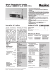
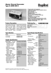
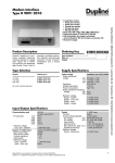
Du line
Master Channel Generator
Types G 3800 0016, G 3800 1016
®
Fieldbus
Installationbus
• Programmable channel generator
• Automatic data exchange between multiple networked Master
Generators, allowing systems with up to 4096 I/O points
• Option for built-in GSM Modem for monitoring and control
via SMS
• User-friendly configuration via Windows 98/2000/NT/XP
software
• Real-time, timer and logic functions
• Analog set-point control and monitoring
• Light and Rollerblind control functions
• Alarm Monitoring
• Option for Radio controlled clock for high real time accuracy
• 2 x RS232 ports for configuration and Dupline data read/write
• 1 x RS485 port for networking of up to 32 Master Generators
• Modbus-RTU protocol
• Built-in software driver for external radio modem
• 4 digital inputs / 4 digital outputs on-board
• H8-housing for DIN-rail mounting (EN50022)
• AC or DC power supply
Product Description
Programmable channel generator with built-in dedicated
intelligent functions for light
and roller blind control, alarm
monitoring and analog setpoint control. In addition to
that, there is realtime-, timerand logic- functions. Programming is easily performed
through Windows-based configuration
software.
An
optional built-in GSM modem
can be used for monitoring
and control of Dupline signals
via SMS. Up to 32 Master
generators can be networked
Ordering Key
as slaves in a RS485 network
using the Modbus protocol.
The unit has 4 digital inputs
and 4 digital outputs onboard, and it is possible to
create links to other Dupline
networks via external Radio
Modem. The G3800X016 is
different from the G3800X015
in that it has the capability to
perform
automatic
data
exchange with up to 32 other
G3800X016’s in a RS485 network, enabling up to 4096
I/O-points in one system.
G 3800 1016 230
Type: Dupline®
H8-housing
GSM phone
Master channel generator
Supply
Type Selection
Supply
Ordering no.
Ordering no.
w. GSM telephone
115/230 VAC
10-30 VDC
G 3800 0016 230
G 3800 0016 800
G 3800 1016 230
G 3800 1016 800
Input/Output Specifications
Serial Port
COM 1
COM 2
Data format
COM 1, COM 2
Pin assignment
TxD
RxD
GND
Dielectric voltage
Com.port - Dupline®
Protocol
RS 485
Termination
Fs-B
Fs-A
+ (B)
- (A)
GND
V+
Protocol
Dupline® Output
Output voltage
Current
Short-circuit protection
RS 232
115 kBaud
9600 Baud, adjustable
8 bit
No parity, 1 stop bit
9-pole female SUB-D
Pin 2
Pin 3
Pin 5
≥ 2 kVAC (rms)
Modbus-RTU
Pin 27 When in use,
connect to pin 31
Pin 28 When in use,
connect to pin 30
Pin 29 When in use,
connect to pin 31
Pin 30
Pin 31
Pin 32
Pin 33*)
Modbus-RTU
Dupline® carrier
8.2 V
< 130 mA
Yes
Sequence time
32 channels / 128 channels
Digital outputs
Function
Output voltage VDD
Output current
Output voltage drop
Off-state leakage current
Short-circuit protection
Built-in protective diodes
Dielectric voltage
Output - Dupline®
Output - Input
Inductive loads
Inputs
Digital
Voltage
Current
Dielectric voltage
Input - Dupline ®
GSM Modem
Siemens cellular engine
Dual Band
Output power
Antenna connector
*)
38.6 ms / 132.3 ms
4 PNP transistors
Programmable
≤ 35 VDC
≤ 100 mA
≤2V
≤ 100 µA
None
None
≥ 4 kVAC (rms)
200 V
External noise suppression
required
6 - 30 VDC
ON > 5.5 V; OFF < 1.5 V
≤ 6 mA
≥ 4 kVAC
TC35
EGSM900 and GSM1800
Class 4 (2 W) EGSM900
Class 1 (1 W) GSM1800
FME
V+ and GND may be used as supply for digital I/O’s, if RS 485 is not used.
Specifications are subject to change without notice (30.06.03)
Dupline® is a registered trademark. A product of the CARLO GAVAZZI Group
Gross Automation (877) 268-3700 · www.carlogavazzisales.com · [email protected]
1
Du line
G 3800 0016, G 3800 1016
®
Fieldbus
Supply Specifications
General Specifications
Power supply
AC-Types
Rated operational voltage
through term. 21 & 24
jumper term. 22 & 23
through term. 21 & 23
jumper term. 24 & 22
Frequency
Rated operational power
Power dissipation
G38000016
G38001016
Rated impulse withstand
voltage
230 V
115 V
Dielectric voltage
Supply - Dupline®
Supply - Output
Supply - Input
Supply - Com. ports
Heat dissipation
Power supply
DC-Types
Rated operational voltage
through term. 21 & 22
Reverse polarity protection
Rated operational power
Power dissipation
G38000016
G38001016
Inrush current
Rated impulse withstand volt.
Dielectric voltage
Supply - Dupline®
Supply - Output
Real-time clock
Accuracy
Internal back-up time
Power ON delay
Indication for
Supply ON
ON Line
COM 1
COM 2
RS 485
GSM
Environment
Degree of protection
Pollution degree
Operating temperature
Storage temperature
Humidity (non-condensing)
Mechanical resistance
Shock
Vibration
Dimensions
Material
(see "Technical Information")
Weight
Overvoltage cat. III (IEC 60664)
230 VAC ± 15% (IEC 60038)
115 VAC ± 15% (IEC 60038)
45 to 65 Hz
Typ. 7 VA/3 W
≤6W
≤7W
4 kV
2.5 kV
≥ 4 kVAC (rms)
≥ 4 kVAC (rms)
≥ 4 kVAC (rms)
≥ 4 kVAC (rms)
4W
Overvoltage cat. III (IEC 60664)
10 to 30 VDC
Yes
6W
Installationbus
Better than ± 1 minute/month
Typ. 48 hours
< 2.5 s
LED, green
LED, yellow
LED, red
LED, red
LED, red
LED, red
IP 20
3 (IEC 60664)
0° to +50°C (+32° to +122°F)
-20° to +85°C (-4° to +185°F)
20 to 80% RH
15 G (11 ms)
2 G (6 to 55 Hz)
H8-housing
640 g
≤6W
≤7W
1A
800 V
500 V
200 V
Wiring Diagrams
DUPLINE
1
2
6-30 VDC
D+
D-
3
1
4
5
6
2
V+
3
V+
V-
4
7
8
9
10
1
2
3
4
IN
11
G 3800 0016 230
V-
12
13
14
15
16
0,1 A
30 V
1
2
3
4
12 VA
33
V+
34
Inputs
21
P
22
115V
23
N P
24
115V
25
26
27
T
28
Outputs
29
30
Fs-B Fs-A (B)
N
31
(A)
RS 485
32
V-
Out
Supply
6-30 VDC V+
DUPLINE
1
2
+
-
21
22
D+
D-
3
4
1
5
6
3
8
9
10
1
2
3
4
IN
11
Radio Contr.
Clock
G 3800 0016 800
V-
12
13
14
15
16
1
2
3
4
Inputs
23
24
25
26
27
Supply
10-265 VAC
10-30 VDC AC monit. input
36
V+
V-
4
7
T
2
2
35
V+ S-in V -
Outputs
28 29 30
Fs-B Fs-A (B)
31
(A)
RS 485
32
V-
33
V+
Out
34
35
36
V+ S-in V -
Radio Contr.
Clock
Specifications are subject to change without notice (30.06.03)
Dupline® is a registered trademark. A product of the CARLO GAVAZZI Group
Gross Automation (877) 268-3700 · www.carlogavazzisales.com · [email protected]
Du line
G 3800 0016, G 3800 1016
®
Fieldbus
Installationbus
Mode of Operation
Intelligent functions
The G3890x016 Master Generator is a programmable channel
generator which is particularly
well suited for building automation applications due to the dedicated intelligent functions for
lighting control, rollerblind control, temperature control and
alarm monitoring. In addition to
that the unit can be configured
to perform real-time, logic and
timer functions. The windowsbased configuration software is
extremely easy to use due to the
pre-programmed functions.
Master Generator configuration
The Master Generator is as
default configured to operate as
a standard channel generator
without intelligent functions. In
order to make use of the intelligent functions the Master Generator must be configured by
means of the user-friendly windows-based configuration software. This is included in the
package and has to be installed
on a Win 95/98/2000/NT/XP PC.
When the configuration is completed the configuration is downloaded into the Master Generator via COM1 (RS232 port). The
configuration can be saved on a
file and it is also possible to
upload the configuration from a
Master Generator.
GSM Modem Option
The G38001016 Master Generator has a built-in GSM Modem
which enables monitoring and
control of Dupline signals via
SMS messages to/from mobile
GSM telephones. There are 3
different ways to use SMS messaging:
• The Master Generator can be
programmed to send out eventbased SMS messages. The
event can be a channel switching ON or OFF, or it can be an
analog signal crossing a setpoint.
• Requests for status of digital
or analog data can be sent and
answered via SMS messages
• Status of digital channels can
be controlled by sending commands via SMS messages
In order to make use of the GSM
modem, the following is required:
• A SIM-card with the pin-code
9090 needs to be inserted into
the slot in the front of
G38001016. The SIM-card must
be a 3V type.
• A GSM antenna needs to be
connected to the FME connector
on G38001016. If the unit is
installed in a metal enclosure,
the antenna must be installed
outside the enclosure and connected to the Master Generator
via a cable (an antenna of this
type is available as accessory).
An LED in the front of
G38001016 indicates the status
of the GSM modem. By emitting
different blink patterns, the LED
indicates "connecting", "SIMcard missing", "No network
found", "No response from
modem", "SMS sent" and "SMS
received".
Radio Controlled Clock Option
It is possible to equip the
G3800x016 with an external
antenna for radio-controlled
clock in order to achieve high
timing accuracy in connection
with real-time functions and
event time stamps. When the
antenna ANT2 is used, the
G3800x016 will receive accurate
timing signals from the DCF77
transmitter located in Frankfurt
a.M., Germany. The antenna outputs the demodulated signals to
the Master Generator via an
open collector driver.
The DCF77 transmitter covers all
of Central Europe since the
transmission radius is at least
1000 km. For longer distance the
use of ANT2 depends on receiver conditions. ANT2 connects to
the G3800x016 terminals.
RS232 ports
The Master Generator is provided with two RS232 ports (COM1
and COM2) which both can be
used
by
PC’s/PLC’s
for
read/write of Dupline data using
the
Modbus-RTU
protocol.
COM1 is also used for download
and upload of configuration files
(created by the Master Generator configuration software) and
for firmware upgrades. If the
option for an external radio
modem is desired, it needs to be
connected to COM2. COM1 has
a fixed baudrate of 115 kBaud,
while the baudrate of COM2 is
adjustable.
RS485 port
The RS485 port enables networking of up to 32 Master Generators with or without automatic
data exchange. This enables
control and monitoring of up to
4096 data points. If desired, it is
also possible to use Ethernet
instead of RS485. In that case
each Master Generator must be
equipped with a converter. A
Modbus Device Address needs
to be assigned to each Master
Generator during configuration.
In a network with automatic data
exchange, one Master Generator
is configured as RS485 Master,
and will thus synchronize a continual automatic data exchange
between all the Master Generators. When programming the
individual Controllers it is then
possible to make references to
signals in other Dupline networks. For example the wind
speed value measured by a sensor in one Dupline network, can
be used in the roller blind control
function in the other Dupline networks. It is also possible to
make e.g. "all lights OFF" functions for a big building by activating a single pushbutton. A PC
or PLC, connected to one of the
COM-ports of the G3800X016
operating as RS485 Master, gets
access to all 4096 data points
using the Modbus protocol.
Also, using the PC makes it possible to change the configuration
in any of the Master Generators
in the network.
In a network without automatic
data exchange, a PC or PLC
need to be RS485 Master and all
the Master Generators will operate as Modbus-RTU slaves. This
makes it possible for the PC or
PLC to read/write data from any
of the 32 Master Generators.
See following RS485 networking
diagram for both operating
modes.
Modbus-RTU protocol
Using the Modbus-RTU commands 2 and 3 through COM1,
COM2 or RS485 makes it possible to read any type of Dupline
data (digital, analink, multiplexed
analog or counter data). The status of digital and multiplexed
analog data and reset of counter
can be controlled via the commands 5, 6 and 16. See manual
for memory map information.
Software
The Dupline Data Access software package (type no. DUPDATACC) has been developed
specifically for the Master Generator. It contains two software
tools that provide easy access
from a PC to Dupline digital,
analog and counter data via one
of the RS232 or RS485 ports.
The DDE-driver provides a
Dynamic Data Exchange interface, which can be used from
applications that support client
side DDE such as Microsoft
EXCEL. Getting Dupline data
into an EXCEL spreadsheet is a
simple copy-and-paste operation. The Dupline ActiveX driver
provides an ActiveX interface,
which is a Microsoft standard for
communication between two
products. The Dupline ActiveX
driver can be used from any
development tool that supports
client side ActiveX such as
Microsoft Visual Basic, Delphi
and Borland C++ builder.
The Dupline Data Access package can be used on single Master Generators as well as Master
Generator networks.
Radio Modem driver
The Master Generator has a
built-in driver for control of an
external Radio Modem, which
can be used to create wireless
links where no cable is available
in parts of an installation. One
Master Generator must be
defined as the central MGEN
and up to 32 Master Generators
can be defined as remote
MGEN’s. The central MGEN is
continuously polling and updating the Dupline data from all
remote MGEN’s via the radio
modem network, and in this way
it makes the entire system operate as one big Dupline network.
Apart from increased reaction
time (depending on the number
of remote MGEN’s), the system
will operate as if it was one Master Generator connected to all
the I/O-modules with cable. The
Master Generator supports the
Radio Modem type 2ASxE and
all 3AS types from the Finnish
manufacturer SATEL (www.satel.fi).
Find below an application diagram for the Radio Modem
option.
Note: Analink modules cannot
be used with Radio Modems.
On-board I/O
The Master Generator has 4 digital inputs and 4 digital outputs
on-board. These have been
implemented to reduce the cost
of remote stations with only a
few signals (e.g. in connection
with an SMS alarm system or
radio modem remote stations).
The onboard I/O’s are used via
the logic functions of the Master
Generator, where they can be
assigned to specific channel
addresses.
Specifications are subject to change without notice (30.06.03)
Dupline® is a registered trademark. A product of the CARLO GAVAZZI Group
Gross Automation (877) 268-3700 · www.carlogavazzisales.com · [email protected]
3
Du line
G 3800 0016, G 3800 1016
®
Fieldbus
Pin Assignment, COM1, COM2
5
1
9
6
Pin
Signal
2
3
5
TxD
RxD
Signal Ground
Installationbus
RS 232 Cable
9-pin male
to controller
2
3
5
9-pin female
to PC
2
3
5
9-pin male
to controller
2
3
5
15-pin female
to radio modem
11
9
7
Master Generator Network
Without automatic data exchange
PC
Interface #1
Dupline #1
Interface #2
Dupline #2
I/O modules
• Digital
• Analogue
• Counter
I/O modules
• Digital
• Analogue
• Counter
Modbus/RS485
With automatic data exchange
PC
Modbus/RS232
MGEN Master #32
Dupline #32
MGEN Slave #1
Dupline #1
MGEN Slave #2
Modbus/RS485
Dupline #2
4
Specifications are subject to change without notice (30.06.03)
Dupline® is a registered trademark. A product of the CARLO GAVAZZI Group
Gross Automation (877) 268-3700 · www.carlogavazzisales.com · [email protected]
Du line
®
G 3800 0016, G 3800 1016
Fieldbus
Radio Modem Application
Installationbus
Scope of Supply
1 x Master Channel Generator
1 x User manual
1 x RS 232 cable
1 x Configuration software
Central MGEN
G 3800 x016 xxx
MAN G 3800 0016 ENG
RS 232-9 M/9 F
SW G 38xx16
RS232
Accessories
Remote MGEN #1
RS232
Dupline Data Access Software DUPDATACC
GSM Antenna 900 MHz
ANT1
Antenna for
Radio controlled clock
ANT2
Remote MGEN #2
RS232
ANT1
ANT2
Specifications are subject to change without notice (30.06.03)
Dupline® is a registered trademark. A product of the CARLO GAVAZZI Group
Gross Automation (877) 268-3700 · www.carlogavazzisales.com · [email protected]
5