1
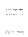
Gadireddy Srikanth Kumar / (IJCSIT) International Journal of Computer Science and Information Technologies, Vol. 3 (3) , 2012,3924-3928 CAN Bus Analyzer for Industrial Applications Gadireddy Srikanth Kumar Ecm Department, K.L.University Vijayawada,India Abstract—In this we are implementing a RS232 based CAN Bus Network analyzer based on ARM7 using acceptance filter concept. ARM7 (LPC2129) microcontroller having two interconnected CAN interfaces with advanced acceptance filters. By using lpc2129 microcontroller receive the data CAN bus, convert the data in serial format and transfer the data to Personal computer(PC) or Laptop using RS232 serial port or virtual serial port. A CAN transceiver MCP2551 is a highspeed CAN, fault-tolerant device that serves as the interface between a CAN protocol controller and the physical bus. The MCP2551provides differentials transmit and receive capability for the CAN protocol controller and is fully compatible with the ISO-11898 standard. The CAN BUS Analyzer is a simple to use low cost CAN bus monitor which can be used to develop and debug a high speed CAN network. The device supports CAN 2.0b and ISO11898-2 and a broad range of functions which allow it to be used across various market segments including automotive, industrial, medical and marine Generally in industries there is traditional network communications like RS232, RS485, etc. are limited for short distances. But the use of intelligent protocol converter provides the practicable solution. The Controller Area Network (CAN) is an International Standardization Organization (ISO) defined serial, asynchronous, multimaster communications bus originally developed for the automotive industry to replace the complex wiring harness with a two-wire bus. The specification calls for high immunity to electrical interference and the ability to self-diagnose and repair data errors. CAN was designed for automotive and industrial applications needing high levels of data integrity and data rates of up to 1 Mbit/s. Today the CAN bus is also used as a field bus in general automation environments; primarily due to the low cost of some CAN Controllers and processors. CAN bus will be increasingly used in wide range of applications for its superiority. A need arises when using CAN buses to monitor the data on the bus as well as having the ability to inject further data onto it. This provides the ability to fully test a CAN network on both the frame level and the bit level. A low cost and portable CAN bus analyzer is requiring testing or Monitoring the CAN bus in the fields.Thus, we are implementing a RS232 based CAN Bus Network analyzer based on ARM7 using acceptance filter concept. Keywords—CAN,ARM7,PIC,RS232,AcceptanceFilterIntroduction . Introduction CAN, by itself, is not necessarily a complete network system. It consists of only the physical layer (the two wires), the priority scheme (highest priority message always gets through first) and some error detection and handling circuitry. This allows simple messages of from zero to eight bytes to be passed on the system. CAN, like most modern networks, is serial based. This means that the information travels along the network one bit at a time’s CAN network needs from one to two lines depending on the design. Parallel networks usually require more than 8 wires plus several handshaking lines to facilitate the data transfer. Most network systems using CAN will employ a higher level Protocol such J1939, CAN open or a proprietary scheme to create and process messages over the basic CAN network. Controller Area Network (CAN) is a network protocol which allows multiple nodes in a system to communicate efficiently with each other. It is a serial communication bus for real time applications which operates at a data rate of 1Megabits per second. CAN is event triggered and not time triggered and is more suitable for a periodic communication. Communication through CAN is very reliable and robust, thus used in noisy environments. CAN is widely used for Automotive Applications to replace the complex wiring problems. Nowadays CAN bus is used for in-car electronics, aerospace, ships, medical electronics and also in Textile machineries.In this we are implementing a RS232 based CAN Bus Network analyzer based on ARM7 using acceptance filter concept. ARM7 (LPC2129) microcontroller having two interconnected CAN interfaces with advanced acceptance filters. By using lpc2129 microcontroller receive the data CAN bus, convert the data in serial format and transfer the data to Personal computer(PC) or Laptop using RS232 serial port or virtual serial port. A CAN transceiver MCP2551 is a high-speed CAN, fault-tolerant device that serves as the interface between a CAN protocol controller and the physical bus. The MCP2551provides differentials transmit and receive capability for the CAN protocol controller and is fully compatible with the ISO-11898 standard. The CAN BUS Analyzer is a simple to use low cost CAN bus monitor which can be used to develop and debug a high speed CAN network. The device supports CAN 2.0b and ISO11898-2 and a broad range of functions which allow it to be used across various market segments including automotive, industrial, medical and marine. 1.1.History of Controller Area Network:- Robert Bosch introduced CAN to be used in Automotive Application in order to reduce the complex wiring problems inside passenger cars. Most of the cars which are manufactured since 1980’s uses CAN as a standard for in vehicle communication. CAN is documented as an International standard as ISO11898 for high speed applications and ISO11519 for low speed applications. To discuss the growth of CAN several user groups have been formed. One of the first is CAN in Automation (CiA). Now in its 20th year CAN is still enhanced. In the future CAN would be used in every type of embedded systems and machines. 3924 Gadireddy Srikanth Kumar / (IJCSIT) International Journal of Computer Science and Information Technologies, Vol. 3 (3) , 2012,3924-3928 debug a high speed CAN network. The tool supports CAN 2.0b and ISO11898-2 and a broad range of functions which allow it to be used across various market segments including automotive, industrial, medical and marine. The toolkit comes with all the hardware and software required to connect a CAN network to a PC. The Graphical User Interface makes it easy to quickly observe and interpret bus traffic. CAN was developed for the automotive market to reduce the weight and cost of wiring harnesses and add additional capabilities. It is also used in factory automation, medical, marine, military and anywhere a simple yet robust network is needed. Block Diagram LPC2129 RS232 to USB converter MCP2551 Fig. 1 Block Diagram of CAN bus How Does Can Works:1.Operation of CAN :- CAN is a bit stream oriented communication protocol through which the complete transmission of message is carried stand alone by the CAN controller. CAN is a broadcast communication system in which the message frames which are transmitted on the bus do not have any source or destination addresses. Instead the Frames have identifiers with which the nodes which receive the messages can run an acceptance test (filtering) to make sure whether to accept the corresponding message or to ignore it. The Identifier has information about the content of data inside the frame and also the priority of the message. Higher the priority, lower the number. The length of the Identifier is normally 11bits (Standard CAN) and the second generation CAN have an Identifier 29 bits (Extended CAN). 2. Bus Arbitration :- CAN use Carrier-Sense Multiple Access with Collision Avoidance“(CSMA/CA) for the bus access. Every node in the network can access the bus when the bus is free for 3 bit period. In case of collision, the message with a higher priority wins the bus access and transmits. If more than one node tries to send data through the bus, then the bus access is decided by a bitwise arbitration. The nodes which needs to send the message transmits the message bits at the same time. The node which sends a dominant (0) bit will gain the access on the bus there on. The other node which sends a recessive (1) bit changes its state to a receiver and starts to receive the message frame which is on the bus. The transmission of lower priority message is stalled and transmitted again automatically when the bus is free. The message contains 0-8 bytes of date which is specified as Data Length Code (DLC) in the Control Bits of the message frame. For the error detection a 15 bit checksum is transmitted along with the message. The CAN BUS Analyzer Tool is a simple to use low cost CAN bus monitor which can be used to develop and CAN BUS CAN Analyze and is a RS232 to CAN PC based port adapter to monitor and analyzes the CAN bus data on a CAN Network. This universal CAN tool can be used in Development, production, quality control, service departments, prototype build shops and other areas. Next to the targeted automotive application field, this tool provides a powerful test tool for all fields and areas of CAN networks. Diagnostic functionality for on-line and off-line is implemented. The main component of the can Analyser is a central communication server, which acts as an interface between the CAN bus (CAN board) and the analysis modules. The actual analysis functions are provided by separate function modules, which can be connected to the communication server in any combination. In addition to the modules provided by IXXAT, specific modules created by the user can also be used. Due to the open programming interface of the can Analyser, customized functionalities in the form of individual modules can easily be integrated. This unique concept guarantees almost unlimited extendibility. About the Project The following report details the development and implementation of a low-cost PC based CAN bus analyzer on ARM7 microcontroller PC2129.The CAN BUS Analyzer Tool is intended to be a simple-to-use, low-cost CAN Bus monitor which can be used to develop and debug a high-speed CAN network. The tool features a broad range of functions which allow it to be used across 3925 Gadireddy Srikanth Kumar / (IJCSIT) International Journal of Computer Science and Information Technologies, Vol. 3 (3) , 2012,3924-3928 various market segments including automotive, marine, industrial and medical. The CAN Analyzer tool supports CAN 2.0b and ISO 11898-2 (high-speed CAN with Transmission rates of up to 1 Mbit/s). The tool can be connected to the CAN network using the DB9 connector or through a screw terminal interface. The CAN BUS Analyzer has the standard functionality expected in an industry tool such as trace, transmit, trace filter and log file capability, and it also integrates some unique features such as ECAN register view and group CAN message transmit. All of these features make it a very versatile tool, allowing fast and simple debugging in any high-speed CAN network. In this project we are implementing a PIC microcontroller based CAN network for demon staring the CAN bus analyzer. In this project, CAN bus protocol is studied. ECAN logic in 18F458 Microcontroller and CAN transceiver chip MCP2551 are studied. Various elements like sensors, lcd’s etc.., here initially sensors are used for sensing the parameters such as temperature, humidity etc.., When the sensing element sense the output ( i.e., changing the input level from one level to other level) will exceeds threshold level and is given to the input of microcontroller. After that the sensing output will monitor on monitor at one end and at the same time it transmits the data to another end through CAN transceiver. At receiving end the CAN transceiver receive the data and it gives to microcontroller. Here microcontroller will gives the data to display the output through the serial communication in monitor. For this we required a suitable hardware to designed Microcontroller and CAN transceiver. Hardware Design 1.ARM LPC2129 microcontroller:1.Architecture: 1. 16/32-bit ARM7TDMI-S microcontroller in a 64 or 144 pin package. 2. 16 kB on-chip Static RAM 3. 128/256 kB on-chip Flash Program Memory (at least 10,000 erate/write cycles over the whole temperature range). 128-bit wide interface/accelerator enables high speed 60 MHz operation. 4. External 8, 16 or 32-bit bus (144 pin package only) 5. In-System Programming (ISP) and In-Application Programming (IAP) via on-chip boot-loader software. Flash programming takes 1 ms per 512 byte line. Single sector or full chip erase takes 400 ms. 6. Embedded ICE-RT interface enables breakpoints and watch points. Interrupt service routines can continue to execute whilst the foreground task is debugged with the on-chip RealMonitor software. 7. Embedded Trace Macrocell enables non-intrusive high speed real-time tracing of instruction execution. 8. Two/four interconnected CAN interfaces with advanced acceptance filters. 9. Four/eight channel (64/144 pin package) 10-bit A/D converter with conversion time as low as 2.44 ms. 10. Two 32-bit timers (with 4 capture and 4 compare channels), PWM unit (6 outputs), Real Time Clock and Watchdog. 11. Multiple serial interfaces including two UARTs (16C550), Fast I2C (400 k bits/s) and two SPIs™. 12. 60 MHz maximum CPU clock available from programmable on-chip Phase-Locked Loop. 13. Vectored Interrupt Controller with configurable priorities and vector addresses. 14. Up to forty-six (64 pin) and hundred-twelve (144 pin package) 5 V tolerant general purpose I/O pins. Up to 12 independent external interrupt pins available (EIN and CAP functions). 15. On-chip crystal oscillator with an operating range of 1 MHz to 30 MHz. 16. Two low power modes, Idle and Power-down. 17. Processor wake-up from Power-down mode via external interrupt. 18. Individual enable/disable of peripheral functions for power optimization. 19. Dual power supply. a. CPU operating voltage range of 1.65V to 1.95V (1.8V +/- 8.3%). b. I/O power supply range of 3.0V to 3.6V (3.3V +/- 10%) 2.Applications:- • Industrial control • Medical systems • Access control • Point-of-sale • Communication gateway • Embedded soft modem • general purpose applications 3.PIC microcontroller:- The original PIC was built to be used with General Instruments’ new 16-bit CPU, the CP1600. While generally a good CPU, the CP1600 had poor I/O performance, and the 8-bit PIC was developed in 1975 to improve performance of the overall system by offloading I/O tasks from the CPU. The PIC used simple microcode stored in ROM to perform its tasks, and although the term was not used at the time, it shares some common features with RISC designs. In 1985, General Instruments spun off their microelectronics division and the new ownership cancelled almost everything which by this time was mostly out-of-date. PIC and PIC micro are registered trademarks of Microchip Technology. It is generally thought that PIC stands for Peripheral Interface Controller. The acronym was quickly replaced with “Programmable Intelligent Computer”. OVERVIEW OF PIC: PIC microcontroller is a very general purpose microcontroller that can come with many different options. General Instruments produced a chip called the PIC1650, described as a Programmable Intelligent Computer. Maybe Microchip has never used PIC as an abbreviation, just as PIC and recently. PIC microcontrollers are finding their way into new applications like smart phones, audio accessories, video gaming peripherals and advanced medical devices. There are hundreds of 8-bit PIC 3926 Gadireddy Srikanth Kumar / (IJCSIT) International Journal of Computer Science and Information Technologies, Vol. 3 (3) , 2012,3924-3928 microcontrollers to choose from ranging from 6 to 100 pins and up to 128 KB Flash that are pin and code compatible. Popularity of the PIC microcontrollers is due to the following factors: 1. Speed: Harvard Architecture, RISC architecture, 1 instruction cycle = 4 clock cycles. 2. Instruction set simplicity: The instruction set consists of just 35 instructions (as opposed to 111 instructions for 8051). 3. Power-on-reset and brown-out reset. Brown-out-reset means when the power supply goes below a specified voltage (say 4V), it causes PIC to reset; hence malfunction is avoided. A watch dog timer (user programmable) resets the processor if the software/program ever malfunctions and deviates from its normal operation. 4. PIC microcontroller has four optional clock sources. Low power crystal Mid range crystal High range crystal RC oscillator (low cost). 5. Programmable timers and on-chip ADC. 6. Up to 12 independent interrupt sources. 7. Powerful output pin control (25mA (max.) current sourcing capability per pin.) 8. EPROM /ROM/Flash memory option. 9. I/O port expansion capability. 10. Free assembler and simulator support from Microchip. CAN Transceiver (MCP2551) CAN transceiver is an interface between protocol controller and the physical bus. The MCP2551 is a high-speed CAN transceiver, fault-tolerant device that serves as the interface between a CAN protocol controller and the physical bus. The MCP2551 provides differential transmit and receive capability for the CAN protocol controller and is fully compatible with the ISO-11898 standard, including 24V requirements. It will operate at speeds of up to 1 Mb/s. Typically, each node in a CAN system must have a device to convert the digital signals generated by a CAN controller to signals suitable for transmission over the bus cabling (differential output). It also provides a buffer between the CAN controller and the high-voltage spikes that can be generated on the CAN bus by outside sources (EMI, ESD, electrical transients, etc.). The device provides transmit capability to the differential bus and differential receive capability to the controller. The transmitter outputs (CANH and CANL), feature internal transition regulation to provide controlled symmetry resulting in low EMI emissions. Both transmitter outputs are fully protected against battery short circuits and electrical transients that CAN occur on the bus lines. The inclusion of an internal pull-up resistor on the transmitter input ensures a defined output during power up and protocol controller reset. For normal operation at 500 baud the ASC terminal is open or tied to GND. For slower speed operation at 125 baud the bus output transition times CAN be increased to reduce EMI by connecting the ASC terminal to VCC. The receiver includes an integrated Filter that suppresses the signal into pulses less than 30 ns wide. Features • Supports 1 Mb/s operation • Implements ISO-11898 standard physical layer requirements • Suitable for 12V and 24V systems • Externally-controlled slope for reduced RFI emissions • Detection of ground fault (permanent dominant) on TXD input • Power-on reset and voltage brown-out protection • An unpowered node or brown-out event will not disturb the CAN bus • Low current standby operation • Protection against damage due to short-circuit conditions (positive or negative battery voltage) • Protection against high-voltage transients • Automatic thermal shutdown protection • Up to 112 nodes can be connected • High noise immunity due to differential bus implementation • Temperature ranges: - Industrial (I): -40°C to +85°C - Extended (E): -40°C to +125°C SOFTWARE DESIGN The software supports two modes of operation; the Standard mode and the Extended mode. In the standard mode, the following basic features are supported: • Sending/Receiving standard CAN frames • Dual channel access (CAN1, CAN2) • Setting acceptance masks to filter the received frames • Logging all session events • Displaying error counters for each channel • Displaying status of each CAN channel • Defining/Saving frames for repetitive usage • Scripting capability for automating scenarios • Automation window - for sending CAN frames automatically: • On reception of a specific CAN frame • On timer basis • Periodically • In the extended mode, some additional features to the ones • mentioned in the standard mode are supported. These are: • Sending/Receiving extended CAN frames • Displaying frame errors: • Display the location within the CAN frame • where the error occurred • Display the error type • Display the error direction (transmission or reception) • Display the error channel • Display the time of the error 3927 Gadireddy Srikanth Kumar / (IJCSIT) International Journal of Computer Science and Information Technologies, Vol. 3 (3) , 2012,3924-3928 • • Display arbitration loss Display the location within the CAN frame where the arbitration was lost • Display the time of arbitration loss • Supporting extended modes: Listen only mode – only receive frames from the CAN bus • Self-reception mode – receive frames sent • by the node itself and ignore acknowledgment error • Single-shot frame transmission – no retransmission trials in case of arbitration loss The application code will be developed in C programming language. The Kiel IDE software will be used to build the hex file for these C programs. Results The below figures are the final results of the System, in which 4 PIC based CAN controllers are inter connected with ARM and all are in connection with the GUI. The in data bytes that are transmitting through the CAN bus are sent to the GUI.In this system each sensor is interfaced to each PIC controller and the sensor information is sent to the ARM and PIC receiver through CAN BUS and there to GUI. If there is any over fault in the sensors the corresponding sensor controlling command is transmitted by the PIC receiver through CAN BUS with standard ID of the node connected with sensor. Conclusions This paper introduced software and hardware design and debugging method of the converter between CAN with acceptance filter and RS232 in detail.Because of modularization design of software,it can help to design other protocol converter.So that improve the efficiency of the design.The modules of CAN reception,transmission, and CAN acceptance filtering have been directly used for the design of automotive electronics.The novel debugging method can enlighten us on the design and debugging work of other protocol converter.The demand of Industrial Field is multivariate.But the complicated task is always on the basis of the basic module. To meet actual demand,we can add and modify on the basis of these basic modules.We throw out some ideas , and hope to get more brilliant ideas from you based on this paper References CAN Bus Analyzer and Emulator, H. Kashif, G. Bahig and S. Hammad,2009. CAN user manual Haskell Presentation: The Serial Communication Interface (SCI) MC9S12-C32 Haskell Presentation: Controller Area Network (CAN) 3928