1
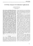
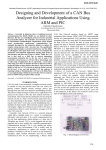
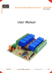
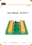
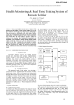
Patel Hiren et al, / (IJCSIT) International Journal of Computer Science and Information Technologies, Vol. 3 (1) , 2012, 3199 - 3204 GUI Based Data Acquisition System Using ARM-Cortex M3 Microcontroller Patel Hiren1, Patel Dipak2 1. Electronics and Telecommunication Dept, BVM Engineering College, Vallabh Vidyanagar,, Gujarat - India 2. Electronics Dept, BVM Engineering College, Vallabh Vidyanagar,, Gujarat - India Abstract— The architectural evaluation in microcontroller development plays important role in the field of embedded systems. The embedded systems in industrial application can be developed around such microcontroller like ARM (advanced RISC machine) to optimize the system performance. This paper includes description about the data acquisition system using ARM Cortex M3 and GUI based LabVIEW software tools. The system designed is not specific for any sensor acquisition, so any sensor having signal conditioning circuit built can be connected to the DAQ card. ARM controller is used as heart of the DAQ. Due to the peculiar features of the ARM Cortex it is used in the system. Keywords— ARM controller, Microcontrollers, Medical Instrumentation, Wearable systems. The data acquisition system designed here has processing part distributed between two systems. Both systems have to perform tasks coherently and individually so that burden does not come upon any one of the systems. These processing systems are classified according to the tasks performed. The DAQ card is capable of taking data from any sensors giving output in designed range of analog input i.e. within reference voltage limits. Signal conditioning of the sensor signals are to be carried out before it could be connected to the system. Computer manipulates the data as well as stores it in a file, thus it also does function of data logging. Along with the data acquisition and data logging it also does communication tasks with DAQ card. I. INTRODUCTION DAQ card is connected to the transducers. The ARM based designs have seen an immense growth transducers cards are having the signal conditioning during the past few years, with free and open software circuit on the PCB. So the signals coming from the tools becoming an integral part of embedded systems transducers are ready to be interfaced with the DAQ development. These free and open source codes offer a card. The system as a whole classified in two primary high-quality tool chain for ARM development. These design modules as, DAQ Card which having ARM systems have acquisition of signals as the basic part [1]. Cortex M3 as a core controller and computer along with All this industries need a platform which can do their GUI (Graphical User Interface) based software for automation jobs. For this generally readily available display of acquired data by software tool LabVIEW DAQ cards from different vendors are available. These from National Instruments inc [4-5]. cards have different features according to design and A. ARM Cortex cost [2]. The DAQ card that we designed has Analog ARM Cortex has wide variation in versions. Differing inputs, Digital inputs and outputs, Interrupts / timers and with the version the features and the applications also at least one PC interface ports like Serial, USB, Ethernet, vary to a great extent. ARM Cortex processor product GPIB etc. families are based on ARMv7 architecture. The MCU The objective was to design the DAQ System to target chosen here falls in mid range of cost and performance. the recent needs in the industries and make it compatible But so far as the system requirements are concerned the with the new trends in the technology. The utilization of Cortex M3 is best suited to the application [6-7]. the facilities, flexibilities and the available recourses to ARMv7 architecture defines a series of three clear match the requirements is targeted in the design. There division of labor: "A" series for cutting-edge virtual are wide ranges of systems available in market which memory-based operating system and user applications; performs data acquisition along with the logging but at "R" for real-time system; "M" series for microcontroller very high rates. This project is designed with keeping in optimized and low-cost applications. mind the recent trends of applications and its ARM Cortex-M series is for those who are very requirements along with the cost constraints. sensitive to the development costs while increasing There are certain other goals which are targeted through performance requirements of small embedded this design which are as included like industrial applications off are designed mainly for the application, affordable to small scale Industries, system microcontroller. can take place of systems based on monitoring The ARM Cortex-M3 processor is a low-power temperature, pressure, humidity, pH level, and other processor that features low gate count, low interrupt sensors as well. latency, and low-cost debug. It is intended for deeply embedded applications that require fast interrupt II. DATA ACQUISITION SYSTEM Generally a system always has a controlling unit or the response, including microcontrollers and automotive processing unit. Function of this unit is to acquire the and industrial control systems. In the industrial field, the data and convert it to the usable format. DAQ card uses user requires a faster speed interrupt, so Cortex-M3 is ARM Cortex series processor for the acquisition and best suited in the industrial applications. conversion tasks. 3199 Patel Hiren et al, / (IJCSIT) International Journal of Computer Science and Information Technologies, Vol. 3 (1) , 2012, 3199 - 3204 B. LM3S8962 – ARMv7 Cortex-M3 Embedded control forms a large part of the market for microprocessors. The embedded controller market has traditionally focused on 8-bit microprocessors, but the growing complexity of many control requirements in sophisticated products indicates a need to move to more powerful processors. The ARM and its variants offer manufacturers the opportunity to move directly to 32-bit controllers at low cost and with a great deal of flexibility for designing custom controllers. The ARM processor is always differed from other commercially available RISC processors in that it is intended to meet a price/performance ratio rather than to be the most powerful processor available. ARM processors offer an extremely good price/performance ratio compared to other processors. The Cortex-M3 processor design has some innovative and much improved features and capabilities when compared with the ARM7TDMI processor. Since the Cortex-M3 processor can finish a task quicker than an ARM7TDMI, more time can be spent in sleep mode, reducing the active power of the system and thereby enabling better system performance and energy efficiency. The architecture uses a Thumb-2 technology and Thumb-2 technology use 31% less memory which reduces system overhead in comparison with the pure 32-bit code. At the same time it provides 38% higher performance than the existing technology solutions based on Thumb. The Stellaris® Ethernet Controller consists of a fully integrated media access controller (MAC) and network physical (PHY) interface device. The Ethernet Controller conforms to IEEE 802.3 specifications and fully supports 10BASE-T and 100BASE-TX standards. In addition, the Ethernet Controller supports automatic MDI/MDI-X cross-over correction. The LM3S8962 ADC module features 10-bit conversion resolution for four input channels, plus an internal temperature sensor. The ADC collects sample data by using a programmable sequence-based approach. ADC acquisition supports single-ended and differential-input configurations at sampling rate of ADC up to 500 thousand samples/second. The start of the conversion can be controlled by various triggering such as Controller (software), Timers, Analog Comparators, PWM and GPIO. The GPIO module supports 5-42 programmable input/output pins. Fig.1 ARM system firmware flow chart A. Main Program Flow Main program module is written to control the execution sequence of the program. The configuration of various hardware modules are carried out within this code. The configuration steps are to be carefully arranged so that it might not conflict with other settings. 1) Clock The card is configured to use main oscillator along with the PLL. Software specifies the output divisor to set the system clock frequency, and enables the main PLL to drive the output. 2) Ethernet The LM3S8962 microcontroller has fully integrated Ethernet controller. Only an RJ45 jack with integrated magnetics and a few passive components are needed to complete the 10/100baseT interface. The LM3S8962 supports automatic MDI/MDI-X so the EVB can connect directly to a network or to another Ethernet device without requiring a cross-over cable. III. ARM FIRMWARE Application software is the layer of software for easily communicating with the hardware. Cortex M3 series of Stellaris family from Texas Instruments supports various tools for programming such as IAR workbench, Code composer Studio and KEIL. Application software code for the ARM processor is classified in two program flows. Fig.2 Interrupt based ADC firmware 3200 Patel Hiren et al, / (IJCSIT) International Journal of Computer Science and Information Technologies, Vol. 3 (1) , 2012, 3199 - 3204 3) ADC The hardware resolution of the ADC is 10 bits. Software based over sampling technique results in an improved Effective Number of Bits (ENOB) in the conversion result. The oversampling gathers additional conversion data from an input signal. Any sampling frequency selected above fS is considered to be oversampling, and when combined with averaging techniques, improves the ENOB. For each bit of accuracy improvement, the signal must be oversampled by a factor of four. This is possible because averaging the oversampled results also averages the quantization noise, thus improving the Signal-to-Noise Ratio (SNR), which has a direct effect on the ENOB. 4) TCP Application TCP/IP is the underlying protocol used for web page transfers, e-mail transmissions, file transfers, and peerto-peer networking over the Internet. For embedded systems, being able to run native TCP/IP makes it possible to connect the system directly to an intranet or even the global Internet. Traditional TCP/IP implementations have required far too much resource both in terms of code size and memory usage to be useful in small 8 or 16-bit systems. Code size of a few hundred kilobytes and RAM requirements of several hundreds of kilobytes have made it impossible to fit the full TCP/IP stack into systems with a few tens of kilobytes of RAM and room for less than 100 kilobytes of code. The uIP TCP/IP stack is intended to make it possible to communicate using the TCP/IP protocol suite even on small 8-bit micro-controllers. Typical code size is on the order of a few kilobytes while RAM usage can be as low as a few hundred bytes. B. TCP and ADC Program Flow This application program consists of 3 sub-programs which are called as per the interrupt generated or any activity detected. These sub-program modules are as listed below: 1) uIP initialization routine The uIP initialization routine includes setting up of the connection with remote host. The IP address of the host terminal and the port number with which connection is to be established is used to connect. 2) Ethernet-Activity routine Whenever there is any activity detected on the ethernet than service routine is executed. This routine checks for the connection, checks for the new data ready to transmit or for the acknowledgement for the previous packet from the host application and sends the new data of ADC if it is ready. After the conversion of the data from ADC channels the ADC interrupt is generated. The interrupt handler routine will clear the interrupt flags, get the data from the FIFOs and make frame to transmit it over ethernet. C. LabVIEW Programming One benefit of LabVIEW over other development environments is the extensive support for accessing instrumentation hardware. Drivers and abstraction layers for many different types of instruments and buses are included or are available for inclusion. The abstraction layers offer standard software interfaces to communicate with hardware devices. The provided driver interfaces save program development time. 1) TCP Tools TCP protocol can be implemented on LabVIEW very easily with TCP tools. TCP tools are readily available with basic installation of LabVIEW. Instead of writing the code for TCP protocol LabVIEW has the building blocks which takes care of everything needed for TCP communication. TCP tools consist of few useful nodes or VIs which are explained in this section. Fig.3 TCP Listen TCP Listen: In any program to start with a TCP communication there has to be a client which listens to the server. Generally a server starts the communication where in the client must be listening to the specified port to establish the communication. This node creates a listener and waits for an accepted TCP network connection at the specified port. “net address” specifies on which network address to listen. “port” is the port number on which you want to listen for a connection. This is the port number of the host computer. “timeout ms” is the period of time in milliseconds to wait for a connection. TCP Open Connection: Whenever server wants to start the connection it has to open a new connection. For opening a new connection we use this node. This new connection requires some specific information such as TCP network connection with the “address” and “remote port or service name”. Fig.4 TCP Open Connection “address” is the IP address of the computer with which connection is to be established. “remote port or service name” can accept a numeric or a string input. “remote port or service name” is the port or name of the service with which we want to establish a connection. TCP Read: Once the connection is connected server will sent he data on the connection. To read that data we use this TCP Read node. It reads a number of bytes from a TCP network connection, returning the results in “data out”. Fig.5 TCP Read “bytes to read” is the number of bytes to read. “data out” contains the data read from the TCP connection. This pin is connected to the string indicator. After reading data this indicator contains data-frame in string 3201 Patel Hiren et al, / (IJCSIT) International Journal of Computer Science and Information Technologies, Vol. 3 (1) , 2012, 3199 - 3204 format. This data is converted to the numeric format for interpretation and plotting. Fig.6 TCP Close Connection TCP Close Connection: Once we complete data acquisition the connections is to be closed separately using their connection ID. TCP Close Connection node closes a TCP network connection. There are few inputs and outputs in the nodes of the toolkit which are undefined due to repetition of those inputs/outputs in previous node description. 2) Host Application DAQ card is connected to the computer for online and offline analysis. There has to be application software which takes the data from the DAQ card and does the interpretation. Host application is the application which runs on the terminal connected directly with the DAQ card. IV. APPLICATION SETUP One of the criteria while designing this application also includes that it has to be stand-alone application software i.e. it can be installed on any machine and start the acquisition process. LabVIEW application builder is very useful tool when we are designing an application that runs on the system that does not have LabVIEW installed on it. Tool of LabVIEW, Application Builder, builds the application exe i.e. executable file as well as installer which can be installed on any machine with required specification. For creating a host terminal which can communicate directly with the DAQ card some setting are to be made. As if, installing the application software, enabling the LAN connection and setting the IP address of terminal to the one specified for establishing the communication. DAQ application can be classified in 2 modules depending upon coding structure as on line Analysis and offline Analysis A. Online Analysis DAQ card continuously acquires the raw data from the transducers and converts it to a digital format. These data is continuously sent to the host terminal. So the analysis can be instantaneous or it can be post analysis. Here we are to discuss the instantaneous analysis mode which is termed here as “Online Analysis”. Fig.8 Code - Online Acquisition The data that are arrived at the ethernet port are taken and converted to the interpretable form. After these data are plotted on the graphs with respect to the time it was received at the terminal. Fig.9 GUI - Graph (Online Acquisition) Fig.7 GUI - Settings Tab V. DAQ APPLICATION Once starts the program he has to give the user-name and password to get access to the acquisition program. After this, activation of process launches the DAQ application. Before starting the acquisition the settings are to be configured. The fig.7 below shows the settings tab for configuring the TCP communication. For TCP Configuration takes Host port as input for listening to connection. Fig.10 GUI - Table (Online Acquisition) Fig.8 shows the part of code which does the acquisition of data through TCP Read node in while loop. TCP read node is configured for acquisition of the 119-bytes of 3202 Patel Hiren et al, / (IJCSIT) International Journal of Computer Science and Information Technologies, Vol. 3 (1) , 2012, 3199 - 3204 data. The acquisition is controlled by the error of the reading node which means if the connection is broken than the acquisition will stop automatically. The data read from the ethernet comes in string format which is manipulated and converted to represent the measure of physical quantity. The data-frame received consists of data from 4-channels with 4-samples each. To display the data on indicators the data of 4-channels are average. The fig.10 shows the graph-tab and table-tab. Until the connection is established the connecting-progress bar will be running. Once the connection is established the graph will plot the received data and table will show the values with time stamp. B. Data Logging Always the data that are coming from the DAQ card are much faster so if detailed analysis is to be carried out than the data must me logged so that time-consuming analysis can be carried out. Even if there is need to compare different data, may be data from different sensors or data from same sensor but for different time than such logged data is very much useful. There is an option given in the settings tab called “Logging”, if this option is selected than the data is logged in a binary file format. The averaged data along with the time stamp and delta time “dt” are collected in an array outside the while loop. The fig.11 shows the code for data logging in a case structure. The file that is created is having the “.DAT” as the extension. Fig.12 Code - Read Data VI VI. CONCLUSIONS The data acquisition designed here integrates a DAQ card which is designed around ARM Cortex M3 MCU and LabVIEW application. The combination of the two proves very beneficial in analysis. Each of the above has unique peculiarities which is utilized together to give best performance required. ARM cortex perfectly matches and is best suited for the solutions related to the automation, acquisition and networking fields. The low cost MCU based design makes system affordable to the industries. The networking capability enables highly efficient data analysis process. The LabVIEW platform interfaces with the ARM based DAQ card. The tools available with it prove very beneficial in developing application faster and easier. VII. FUTURE WORK Data acquisition with networking facilities was the foremost aim of the design. Few more features could be included to make system more reliable, more efficient and more user friendly. Report generation will generate the report for the logged data. DAQ card can be connected in LAN for analysis from remote terminal present on LAN. DAQ card can be connected with Internet so that data can be accessed from any internet connected computer. Fig.11 Code - Writing Data C. Post analysis Retrieving data is carried out in post-analysis part. Because the data format is very important in reading the data back to the display controls. For example if the data written is having 5-bits precision and if reading part tries to read 4-bit or 6-bit precision data than due to the mismatch of the data types the reading node will send error for mismatch of the data. So it is very essential to select proper data types as well as match the same for reading part. The fig.11 shows the reading code. This code consists of a file-I/O node which reads the data from file which is browsed by the user and posts it to the waveform indicator. Along with the display of the data, the values are also shown in table format. [1] [2] [3] [4] [5] [6] [7] [8] REFERENCES Jeffrey Travis, Jim Kring: LabVIEW for Everyone: Graphical Programming Made Easy and Fun, 3rd Edition, July 27 2006, Prentice Hall. Part of the National Instruments Virtual Instrumentation Series. eBook- ISBN-10: 0-13-241224-1, ISBN13: 978-0-13-241224-7 User Manual “Introduction to Data Acquisition” from http://zone.ni.com/devzone /cda/tut/p/id/3536 User Manual LabVIEW 8.2 "Building a Stand-Alone Application" National Instruments http://zone.ni.com/reference/en-XX/help/371361B-01/lvhowto/ building_ a _stand_alone_app/ . Bruce Mihura “LabVIEW for Data Acquisition” Published on June 26, 2001 by Prentice Hall eBook- ISBN-10: 0-13-244127-6, ISBN-13: 978-0-13-244127-8 Application Note “ADC Oversampling Techniques for Stellaris® Family Microcontrollers” http://www.ti.com/stellaris Application Note “Using the Stellaris® Ethernet Controller with Micro IP (uIP)” http://www.ti.com/stellaris Stellaris® LM3S8962 Microcontroller-datasheet http://www.ti.com/stellaris Jan Axelson “EMBEDDED ETHERNET AND INTERNET COMPLETE Designing and Programming Small Devices for 3203 Patel Hiren et al, / (IJCSIT) International Journal of Computer Science and Information Technologies, Vol. 3 (1) , 2012, 3199 - 3204 Networking Create tiny Web servers and use TCP/IP to communicate over local networks & the Internet” Published by Lakeview Research LLC [9] Guido Moritz, Steffen Prüter, Dirk Timmermann “Real-Time Service-oriented Communication Protocols on Resource Constrained Devices” International Multiconference on Computer Science and Information Technology, ISBN 978-8360810-14-9 [10] Adam Dunkels “Full TCP/IP for 8-Bit Architectures” International conference on mobile applications, systems and services (MOBISYS 2003), San Francisco, May 2003. 3204