1
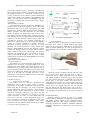
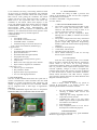
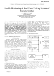
Madhuri Unde et al, / (IJCSIT) International Journal of Computer Science and Information Technologies, Vol. 5 (3) , 2014, 2828-2832
Remote Vehicle Tracking & Driver Health
Monitoring System Using GSM Modem & Google
Maps
Madhuri Unde, Bharat Borkar
Information Technology Department, Amrutvahini College of Engineering,
Sangamner, (M.S.) India-431005
Abstract— Around the world, the number of vehicles theft
cases has been increasing at an rapid rate whereas the rate of
recovery of the stolen vehicles is still minimal. Furthermore,
many service provider companies lack proper fleet
management system which causes low efficiency of services
and reduced profit as the company could not monitor
transportation operations. A real-time remote vehicle tracking
system is one of the possible solutions to overcome these issues.
This paper presents the development of the remote vehicle
tracking system which integrates the Global System for
Mobile Communications (GSM) Modem and Google Map. The
GSM modem at the control centre will receive the coordinates
through Short Message Service (SMS) and updates the main
database. The information then will be accessed by the website
and the position of the vehicle will be displayed through the
Google Maps application. A website has been developed to aid
the user to track and view the vehicles’ location and can be
access anytime and anywhere as long as Internet connection is
available. The three working functions are the latest tracked
vehicle location, route history and route planner. The
developed remote vehicle tracking system demonstrates the
feasibility of real-time tracking of vehicles, which can be used
for many applications including vehicle security and fleet
management.
Keywords— GPS, GSM, Vehicle tracking, Google maps
I.
INTRODUCTION
In urban life transportation is very common. A lot of
mishappenings occur on the road every day .Therefore the
need of security and monitoring is developed. To resolve
such
Various problems that we face, a system is developed using
GPS and GSM technologies and an application is
introduced in this research work [4].
Generally we face following problems:
1. In critical condition (when vehicle is stolen), one is
confused what to do
2. If one has something expensive and he wants to check it
regularly
3. How to monitor the drivers health
All these problems are overcome by this system [4].
The system is composed of two parts, which are
portable remote vehicle tracking unit and the monitoring
centre. The portable remote vehicle tracking unit consists of
Advanced RISC Machines (ARM) with the embedded
operating system, GPS and a GSM, temperature sensor and
heart bit sensor.
This system has Global Positioning System (GPS)
which will receive the coordinates from the satellites among
www.ijcsit.com
other critical information. Tracking system is very
important in modern world. This can be useful in driver
health monitoring, tracking of the theft vehicle and various
other applications. The system is microcontroller based that
consists of a global positioning system (GPS) and global
system for mobile communication (GSM). This project uses
only one GPS device and a two way communication
process is achieved using a GSM modem. GSM modem,
provided with a SIM card uses the same communication
process as we are using in regular phone. The system
allows to track the target anytime and anywhere in any
weather conditions [1].
II.
PROPOSED SYSTEM
The proposed work of this paper is to develop a
system that can be used with real-time wireless monitoring
systems which are designed and implemented through GPS
network and are able to record and transmit bio-signals of
drivers. The aim of this paper is to provide a health
monitoring for the driver at any time and any place and to
design a vehicle tracking system using GSM and GPS to
provide wireless system for monitoring the parameters of
driver are as – Body temperature & Blood pressure.
A. System Architecture
Here there are 2 units in given system
1. Vehicle tracking & driver health monitoring unit
2. Control unit
1. Vehicle tracking & driver health monitoring unit
This unit is placed on the vehicle. It has mainly 2 parts:
a. Biomedical sensors
b. GPS + GSM unit.
a. Biomedical sensors:
Here to find the health status of driver I am using a
body temp sensor as well as pulse rate sensor.
Driver health indicator:
This unit is placed on the driver. Here the electrodes
are placed on various parts of driver. This gives the pulse
rate of the driver .This data is then amplified using the
instrumentation amplifier. The ARM receives this data and
calculates the pulse rate of the driver.
b. GPS+GSM unit:
The GPS is used to log the longitude and the latitude of
vehicle which is stored in the µc memory. The GSM unit
sends an SMS to the control station containing the location
of vehicle.
2828
Madhuri Unde et al, / (IJCSIT) International Journal of Computer Science and Information Technologies, Vol. 5 (3) , 2014, 2828-2832
Fig. 1 Architecture of System
2. Control unitUpon receiving the SMS, the VB s/w sorts the
vehicle’s location based on the GPS co-ordinates. In this
way the control station can keep a track of all their vehicles.
Similarly, control station can also send reply to the
corresponding driver through VB screen in terms of SMS. It
is necessary for the control station to guide the driver on a
correct path if he is lost in the way. The paper has an idea of
tracking the vehicle. By using the location sent by the GPS,
the control station can understand the position of vehicle
(Latitude and Longitude). The base station can access the
current status of the vehicle which is displayed on the PC
and hence take an immediate action by sending help for the
driver or sending backup for the threat ahead
Fig. 2 Block Diagram of System
www.ijcsit.com
III.
DESIGN DESCRIPTION
All the design of proposed system are described in the
following.
A. Hardware Description
The main part of system is microcontroller which will
access the data. In this paper we will use ‘ARM’ controller.
To measure temperature of driver there will be a
temperature sensor. To convert the output of sensor into
electrical form we will use signal conditioning (transducer).
As controller operates only on digital data, so this analog
data is to be converted into digital form by using ADC. But
ADC is inbuilt in ARM processor. So the output of the
signal conditioner circuit is directly connected to ARM
processor.
B. ARM 7- LPC 2148
The ARM7TDMI-S is a general purpose 32-bit
microprocessor, offers high performance and very low
power consumption. ARM architecture is based on RISC
principles, instruction set and related decode mechanism are
simpler than CISC Pipeline techniques employed ARM
Processor supports
both 32-bit and 16-bit instructions via the ARM and Thumb
instruction sets. The 3 parameters to be monitored are
sensed using respective sensor and data is feed to ARM7.
Traditionally, embedded devices include two types of
processors: a Microcontroller and a DSP to process signals.
However, with the development of ARM processors, last
two can be replaced by one single processor. This unit is the
2829
Madhuri Unde et al, / (IJCSIT) International Journal of Computer Science and Information Technologies, Vol. 5 (3) , 2014, 2828-2832
heart of the complete system. It is actually responsible for
all the process being executed. It will monitor & control all
the peripheral devices or components connected in the
system. In short we can say that the complete intelligence
of the project resides in the software code embedded in the
ARM 7. The code will be written in Embedded C and will
be burned or programmed into the code memory using a
programmer.
LPC2148 Micro controller:
LPC2148 Microcontroller Architecture.TheARM7 is a
general purpose 32-bit microprocessor, which offers high
performance and very low power consumption. The ARM
architecture is based on Reduced Instruction Set Computer
(RISC) principles, and the instruction set and related
decode mechanism are much simpler than those of micro
programmed Complex Instruction Set Computers (CISC).
This simplicity results in a high instruction throughput and
impressive real-time interrupt response from a small and
cost-effective processor core. Pipeline techniques are
employed so that all parts of the processing and memory
systems can operate continuously. Typically, while one
instruction is being executed, its successor is being
decoded, and a third instruction is being fetched from
memory. ARM7TDMI-S processor also employs a unique
architectural strategy known as Thumb, which makes it
ideally suited to high-volume applications with memory
restrictions, or applications where code density is an issue.
The key idea behind Thumb is that of a super reduced
instruction set. Essentially, the ARM7TDMIS processor has
two instruction sets:
• The standard 32-bit ARM set.
• A 16-bit Thumb set.
The Thumb set’s 16-bit instruction length allows it to
approach twice the density of standard ARM code while
retaining most of the ARM’s performance advantage over a
traditional 16-bit processor using 16-bit registers. This is
possible because Thumb code operates on the same 32-bit
register set as ARM code. Thumb code is able to provide up
to 65 % of the code size of ARM, and 160 % of the
performance of an equivalent ARM processor connected to
a 16-bit memory system [7].
C.Health monitoring
I.
Temperature sensor LM35
The LM35 series are precision integrated-circuit
temperature sensors, whose output voltage is linearly
proportional to the Celsius (Centigrade) temperature. The
LM35 thus has an advantage over linear temperature
sensors calibrated in ° Kelvin, as the user is not required to
subtract a large constant voltage from its output to obtain
convenient Centigrade scaling [8]. The LM35 does not
require any external calibration or trimming to provide
typical accuracies of ±1⁄4°C at room temperature and
±3⁄4°C over a full −55 to +150°C temperature range. Low
cost is assured by trimming and calibration at the wafer
level. The LM35’s low output impedance, linear output,
and precise inherent calibration make interfacing to readout
or control circuitry especially easy
www.ijcsit.com
Fig.3 health monitoring functions
II.
Heart Bit Sensor
Heart beat sensor is designed to give digital output of
heart beat when a finger is placed inside it. This digital
output can be connected to ARM directly to measure the
Beats per Minute (BPM) rate. It works on the principle of
light modulation by blood flow through finger at each
pulse.
Fig.4.Non in ipod
The Non in iPod is a digital oximeter and sensor that
goes over the user’s finger. The unit itself is simply a
module that can be readily integrated into a host device.
The module measures the blood oxygen level and pulse
rate. The oximeter and sensor is contained in a single unit,
saving space in the final product. The iPod will be
integrated into the system via a 3-wire interface with serial
communications, similar to that of the LM92 temperature
sensor. Since it is a digital output the unit will interface
with the MICA2 via the digital inputs. The ipod has a
minimum operating voltage of 2V with a maximum of 6V,
thus matching the specifications of our supply voltage of
3V.
D.GPS RECEIVER
Generally message received by GPS is in NMEA
[National Marine Electronics Association] message format
and NMEA protocol which is most commonly used is
NMEA0183 Protocol. GPS sentences beginning with the
following specifications: $GPGGA, $GPGSA, $GPGSV,
$GPRMC, and $GPVTG. And sentences also begins with
$GPMSS.
2830
Madhuri Unde et al, / (IJCSIT) International Journal of Computer Science and Information Technologies, Vol. 5 (3) , 2014, 2828-2832
1) The Method of Tracking: The tracking method is based
on the process of collecting continuously the coordinate
(latitude, longitude) of mobile vehicle that could get from
GPS receiver. After getting the coordinate, the mobile
vehicle will send it to the supervised center via SMS or
GPRS service. The supervised center will receive the
coordinate of the mobile vehicle then displays on the
screen. The mother board on the mobile vehicle is equipped
a GSM modem- GM862 and it is directed by a 32bits
microcontroller ARM Cortex M3-LM3S2965. The
microcontroller uses serial interface to communicate with
GM862 by AT commands and send current position of the
vehicle via SMS service by send the sequences
commands below:
2) Commands:
• AT+CMGF=1<CR>
• AT+CMGS=”0937856377”<CR>
• send SMS content : coordinate
• send the message issue Crtl-Z char (0x1A)
<CR>: carrier return character (0x0D hex)[5].
3) Applications:
•
Automotive
• Personal/Portable Navigation(PDA)
• Sports and Recreation
• Personal/Portable Navigation (PDA)
• Geographic Surveying
• Ultra low power design (38mA, typical)
• Compact size
• Built-in low noise, high gain active antenna
• Super-cohesive magnetic for installation
4) Benefits to User:
• Ultra low power consumption
• Easy and fast to install
• Superior urban canyon performance
• Low cost with high performance
E. GSM HARDWARE
The core of data communication about this system lies in
wireless communication control terminals that uses GSM
Modules to transfer long-distance data extensively and
reliably. It Support instructions of AT commands. SIM300
can be integrated with a wide range of applications.
SIM300 is
a Tri-band GSM/GPRS engine that works on frequencies
EGSM 900 MHz, DCS 1800 MHz and PCS1900 MHz
IV. SOFTWARE DESIGN
This includes the coding of ARM 7 processor and
coding for downloading of data and for GUI (Graphical
User Interface) on server side.
For ARM 7 :Embedded c using Keil software.
For GUI :VB.Net
1.
2.
3.
4.
5.
6.
7.
V. ADVANTAGES OF PROPOSED SYSTEM
The system is integrated with Google Map to ease
users in viewing and locating their vehicle
whenever and wherever as long as there is an
internet connection (remotely accessible).
The system will use the inexpensive Short
Message Service (SMS) to transmit the location
information.
The system is simple and can be easily customized
for a variety of applications since it uses the
popular Google Map Application Programming
Interface (API) and common website programming
languages.
Tracks latest vehicle position.
Tracks latest vehicle Route.
Destination and route planner.
Driver health monitoring so that we can help
drivers in panic situations.
VI. CONCLUSIONS
From the above designed system I can conclude
that we are able to transmit the data which is sensed from
remote vehicle to the server PC by using wireless
transmission technology GPS. It is completely integrated so
that it is possible to track anytime from anywhere. It has
real-time capability, emerges in order to strengthen the
relations among people. The accuracy of system is affected
by some factors such as weather, environment around the
mobile vehicle and driver unit, GPS receiver, compass
sensor and the variation between True North Direction and
Magnetic North Direction,etc.
VII .FUTURE SCOPE
There is always chance to improve any system as
research & development is an endless process. The
following measurements can be done in future”
1.
2.
3.
4.
5.
Fig. 5. GSM module
www.ijcsit.com
We can optimizing the hardware system,
choosing a suitable GPS receiver and
compass sensors.
Improving the routing algorithm can be
improved by neural network.
Upgrading this setup is very easy which
makes it open to future a requirement which
also makes it more efficient.
Fuel management
Fully integrated system in a box can be
developed for commercial purposes.
ACKNOWLEDGEMENT
I would like to express gratitude to my guide Mr.Bharat
Borkar for supporting me to do this.
2831
Madhuri Unde et al, / (IJCSIT) International Journal of Computer Science and Information Technologies, Vol. 5 (3) , 2014, 2828-2832
REFERENCES
[1]
[2]
[3]
[4]
[5]
Mohammad Ridhwan,Ahemad Faud,Micheal drieberg, “Remote
vehicle tracking system using GSM modem and Google maps”,
IEEE conference on Sustainable Utilization and Development in
Engineering and Technology- 2013.
Ushasree.K, Hameed Pasha, “Protection system for VIP’S with
GPRS & Remote monitoring”, International Journal of Computer
Trends and Technology- volume2Issue2- 2011.
Rubina.A.Shaikh, “Real Time Health Monitoring System Of
Remote Patient Using Arm7”, International Journal of
Instrumentation, Control and Automation (IJICA) ISSN: 22311890, Vol-1 Iss-3,4, 2012.
Abid khan, Ravi Mishra, “GPS – GSM Based Tracking System”,
International Journal of Engineering Trends and Technology
Volume3 Issue2- 2012.
Pooja Sathe, “Gprs Based Routing & Tracking Of Mobile Vehicles
Using Arm”, International Journal of Engineering Research and
www.ijcsit.com
[6]
[7]
[8]
[9]
Applications (IJERA) ISSN: 2248-9622 www.ijera.com Vol. 2,
Issue4, July-August 2012, pp.1088-1090.
Ya-lin Miao†, Xiang-lin Miao, Zheng-Zhong Bian , Yong-jie Zhan
“Design and Application of Embedded System Based on ARM7
LPC2104 Processor in Telemedicine”, Proceedings of the 2005
IEEE Engineering in Medicine and Biology 27th Annual
Conference Shanghai, China, September 1-4, 2005.
UM10139 Volume 1: LPC214x User Manual, Rev. 01 -15 August
2005, Philips Semiconductors.
Hui Hu, Lian Fang “Design and Implementation of Vehicle
Monitoring System Based on GPS/GSM/GIS” Third International
Symposium on Intelligent Information Technology Application
,School of Information Engineering, East China Jiao Tong
University, Nanchang, Jiangxi, China in 2009. Pages 278-279.
Thuong Le-Tien, Vu Phung-The “Routing and Tracking System for
mobile Vehicles in Large Area”, Fifth IEEE International
Symposium on Electronic Design, Test & Applications Dept. of
Electrical Electronics Engineering, HCM University of Technology,
Vietnam in 2010.
2832