1
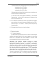
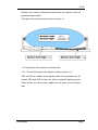
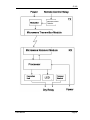
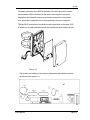
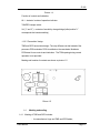
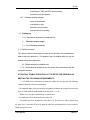
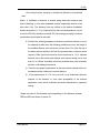
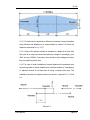
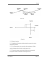
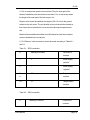
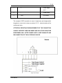
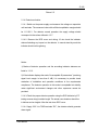
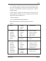
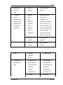
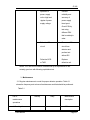
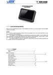
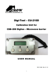
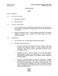
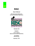
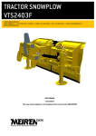
R-300
Microwave Perimeter Protection Detector
R-300
USER MANUAL
US Toll Free: 1 -886-534-2STR
Phone: +1-416-657-4434
Fax: +1-416-650-9012
www.STRsecurity.com
[email protected]
Revision 1.2_______________________________________________________05.07.2005
User Manual
Page 1
R-300
Contents
Introduction
1. Description and operation
1.1 Detector’ application
1.2 Detector’ technical specifications
1.3 Detector’ structure
1.4 Marking and sealing
1.5 Packaging
2. Detector proper usage
2.1 Pre -installation operations
2.2. Detector application
3. Maintenance
4. Storage
5. Transportation
6. Utilization
This operation manual contains information concerning application, design,
operation, technical specifications, structure of microwave barrier R300
(hereinafter “Detector”) and installation and maintenance instructions
necessary for the most effective usage of its technical potential.
Attention!
1. Manufacturer constantly works at detector upgrade, so some
modifications may be made which, however, does not affect its normal
function.
TM
2. Detector uses the new technology “DIGILON “ facilitating its
operation. It is recommended to read this manual before detector
installation.
User Manual
Page 2
R-300
The abbreviations used in the manual are the following:
RC –
remote control
PSU-
power supply unit
DZ-
detection zone
IAK-
installation assembly kit
IS-
initial settings
TMR - transmitter
RCR - receiver
CP -
control panel
1. Description and operation
1.1. Detector application.
The detector is intended to be used as alarm detector and provides the
detection of a human crossing the detection zone.
The detector is designed to operate 24-hour in outdoor conditions with
temperature range from – 40 up to + 65 C, 100% relative humidity at +25 C air
temperature.
Detector is supplied from 12 – 27V DC PSU.
1.2 Detector technical specifications
1.2.1 The detector provides 24-hour outdoor operation and is able to withstand
the following weather and terrain conditions:
-precipitation (rain, snow)
-solar radiation
-wind with speed no more than 30m/s
-surface irregularities with height no more than +/- 3m
-grass height up to 0.3m
User Manual
Page 3
R-300
-snow height up to 0.5 m (without additional adjustments)
1.2.2
The detector’s DZ length is from 10 up to 300 m (measured by received
signal with not less than 9 dB level).
1.2.3
DZ height in its centre is not less than 2 m (at maximum DZ length).
1.2.4
The detector generates alarm signal in form of output circuit open state
and duration not less than 2s when:
1) A walking or crawling human crosses DZ with 0.1 -10 m/s speed;
2)
Impulse with 5-30 V amplitude and more than 0.5s duration is
applied to the transmitter remote control input (RC);
3) PSU is failed or its voltage is less than 10V;
4) RCR case is opened;
5)
Any of the detector’s units fails;
6)
Receiver’s normal operation is disturbed by trespasser using
external electromagnetic field;
1.2.5
Detector’s output circuit of provides current switching up to 0.1 A at
72 V.
1.2.6 RC input resistance s is 10 k.
1.2.7
The detector normal operation is provided by 10-30 V DC power
supply unit.
1.2.8. Detector’s current consumption is no more than 70mA at 24V DC.
1.2.9 Detector size (without initial assembly kit IAK) is 160 x115 x 45 mm
1.2.10 Detector weight (without IAK) is not more than 0,5 kg
1.2.11 Working frequency is 9500+/-200 MHz
1.2.12 Detector generates 7 different messages:
User Manual
Page 4
R-300
1) “Alarm”- the indicator is glowing and contacts of output relay are open for
not less than 2 s, but no more than 30 s, tamper switch contacts are
closed;
2) “Protection”- the indicator is not glowing, contacts of output relay and
tamper switch are closed;
3) “Power supply voltage deficiency”- the indicator blinks with 2 s period (1
sec flashes and 1 sec is off), contacts of output relay are open (for more
than 30 sec), tamper switch contacts are closed.
4) “Unacceptable IS parameters”( receiving signal level margin is less than 9
dB) - Indicator blinks with 2 sec period (0.25 sec flashes, 1,75sec is off)
,contacts of output relay are open, tamper switch contacts are closed;
5) “Defect” –the indicator on control panel is glowing, contacts of output relay
are open (for more than 30 sec); tamper switch contacts are closed.
6) “Breaking in”- tamper switch contacts are open.
7) ‘Normal operation”- if 5-30 V and 0.5 sec duration pulse is applied to the
detector RC input the indicator glows, contacts of output relay are open
(for 2-3 sec), tamper switch contacts are closed.
1.2.13 The detector is ready for operation after power supply turns on - less
than 30 sec. The detector does not generate alarm signal before
switching to stand -by mode.
1.2.14 The detector recovery time after alarm signal termination – not more
than 10 sec.
1.2.15 The adjustment mechanism provides turning of the detector units to
+/- 15 degree angle in any plane.
1.2.16 The detector operates normally and does not generate false alarm
signal when it is separately influenced by the following sources of
interference:
1) Moving human at the following distances from protected zone axis:
User Manual
-
not less than 3 m if PZ is 300 m,
-
not less than 2 m if PZ is 200 m,
-
not less than 1.5 m if PZ is 100 m.
Page 5
R-300
2) Moving transport at the following distances from protected zone axis:
-
not less than 4.5 m if PZ is 300 m,
-
not less than 3.2 m if PZ is 200 m,
-
not less than 1,8 m if PZ is 100 m.
3) Moving single small animal (bird) in protected zone at a distance not
less than 5 meters from detector’s units.
4) Ultra short waves radio stations broadcasting in 150-175 MHz
frequency band
with up to 40 W output power at a distance not less
than 5 m from detector’s units.
1.2.17 The detector is protected from power supply positive and negative
poles confusion (as a result of personnel mistake) and from 1000 V
pulses with up to 1 ms duration
caused by storm and picked by
connection wires.
1.2.21 Average detector life time is not less than 8 years.
1.3 Detector’ structure
1.3.1 Principle of operation
The TMR sends electromagnetic waves to the RCR. The RCR analyzes
amplitude and temporal features of the received signal and in case these
features are in coincidence with those embedded in “intruder” model
processing algorithm the detector outputs alarm signal.
Attention! The detector “R-300” belongs to linear
(perimeter) detection devices. In contrast to volumetric
detection devices which are able to detect movement of
the intruder within the protected zone, “R-300” generate s
alarm signal on crossing the protected zone by intruder.
Therefore, for the detector “R-300” the alienation zone width is standardized
(not the protected zone width).
User Manual
For moving humans and transport the
Page 6
R-300
alienation zone width is determined outside which the detector would not
generate the alarm signal.
The shape of the protected zone is shown on picture 1.1.
1.3.2. Description of the detector’s functional chart.
1.3.2.1 The functional chart of the detector is shown on picture 1.2
TMR and RCR are located at the opposite sides of the protected zone. All
external TMR and RCR circuits have built-in unattended lightning guards.
These devices as well as power supplies are not shown on the functional
chart.
User Manual
Page 7
R-300
User Manual
Page 8
R-300
The TMR includes modulator, transmitting microwave module and selector of
remote control (RC) signal. The modulator generates impulses which are
supplied to the microwave module. The RC selector standardizes level of the
signal applying to the according TMR input and provides proper selection
between signal and interference.
The RCR contains receiving microwave module, processor, executive
device, indicator and case breakage sensor.
The microwave module receives electromagnetic emission signal, detects
and amplifies it.
The processor fulfills the following operations:
- controls microwave module in order to provide the optimization the
received signal;
- determines optimal threshold detection parameters and checks input
signal compliance to these determined parameters;
- checks power supply voltage;
- checks executive device and indicator;
The execution unit is solid-state relay which is, unlike electro-mechanic
relays, more reliable and has practically unlimited life-time.
The indicator is a service device and provides the indication of all detector’
modes of operation.
When TMR receives RC signal, the modulator stops applying impulses to
microwave module. Alarm signal is generated as a result.
1.3.2
Detector’ design
1.3.2.1 The detector is implemented as two separate units which are similar in
form and size.
1.3.2.2 Receiver’ design (picture 1.3)
User Manual
Page 9
R-300
The bearing structure of the RCR is the basis of its case. Microwave module
and processor PCB are fastened on the basis covered by the cover plate.
Adjustment and indication controls as well as the contacts for control panel
zone termination component can be accessed when the cover is opened.
TRM and RCR connection is provided via cable termination on the basis. RCR
is installed on the pipe and fastened with the bracket and two buckles from ISA.
Picture 1.3
The location and marking of the contacts, adjustment and indication controls
are shown on the picture 1.4.
User Manual
Page 10
R-300
Picture 1.4
Function of controls and indication:
HL1 – detector’ modes of operation indicator
TAMPER- tamper switch
X4 (“1” and “2”) - contacts of sensitivity change bridge (initial position”1”
corresponds the lowest sensitivity).
1.3.2.3 Transmitter’ design
TMR and RCR have similar design. The only difference is that instead of the
processor PCB modulator PCB is installed on the case basis. Modulator
PCB doesn’t have controls and indication. The TRM opening during normal
operation is not provided.
Marking and location of contacts are shown on picture 1.5.
Picture 1.5
1.4
Marking and sealing
1.4.1 Marking of TMR and RCR includes:
User Manual
the manufacturer’ logo and TMR and RCR labels;
Page 11
R-300
1.4.2
-
manufacturer’ TMR and RCR serial numbers;
-
production year and quarter.
Package marking includes:
-
name of the detector;
-
manufacturer’ logo;
-
detector’s serial number;
-
year and month of packing.
1.5 Packaging
1.5.1 The detector is packed in cardboard box.
2.
Detector’ proper usage
2.1 Pre-installation operations
2.1.1 Safety measures
The safety measures and electrical code should be taken into consideration
when running the detector in. The detector’ level of radiation allows to run the
system without time restrictions.
2.1.2 Requirements to installation site
2.1.2.1 Actual detector location on the site should be in accordance with the
equipment scheme.
ATTENTION! STABLE OPERATION OF THE DETECTOR DEPENDS ON
MEETING THE FOLLOWING REQUIREMENTS!
2.1.2.2 Buffer zone is determined providing the reliable detector operation. The following
conditions should be taken into consideration:
- The maximum height of the ground surface irregularities relating to the straight line between the
bases of TMR and RCR stands should not be more than +/- 0.3m;
- Bushes, trees, big objects and buildings are not allowed;
- Acceptable grass level should not be more than 0.3m;
- Acceptable snow level should not be more than 0.7m. The detector is able to operate when
the snow level is more than 0,7m but it should be taken into consideration that it may not detect a
human moving in the snow.
User Manual
Page 12
R-300
- No moving humans, transport or animals are allowed in the protected
zone.
Notice: 1) Installation of detector is allowed along obstruction surfaces and
walls of buildings. In this case acceptable surface irregularities should not be
more than 0,3m. The distance from any surface to the detector installation
location should be 0,7 -1,3 m. Water flow from the roof nearby detector ( up to 5
m from the PZ axis) should be excluded. PZ overcoming by jumping from these
constructions should also be excluded.
2) To detect the climbing trespasser it allowed to install the detector on top of
the obstructive walls when the following conditions are met: the height of
the installed detector units should be not less than 0,2 m from the top of
the barrier and not less than 2m from the ground surface, maximum sector
length is 150m (two times less than it was mentioned in 1.2.2), distance
between top of the barrier and detector units across should not be less
than 0,2 m. Barrier immobility should be provided along with immobility
detector units relating to the barrier.
3) There are no special requirements to the area located outside radio nontransparent (metal, reinforced concrete) barriers.
4) If the requirements of 2.1.2.2 are not met it may deteriorate technical
features of the detector. In such case acceptability of the detector
application under actual conditions should be determined by operation
testing.
Shape and size of the alienation zone depending on the distance between
TMR and RCR are shown on picture 2.1
User Manual
Page 13
R-300
2.1.2.3 To eliminate the interference influence to detector’s normal operation
along railways and highways it is recommended to extend 1.5-2 times the
distances mentioned in 6 (1.2.17).
2.1.2.4 Units of the detector should be installed at a distance not less than
20m and 30 m away from power lines when the voltage is, accordingly, up to
35kV and up to 500kV. Connection lines should be laid underground when
they run parallel to power lines.
2.1.2.5 In case of serial installation of several detectors the protected zone
overcoming under or above installed units could be avoided by ”overlapping”
of adjacent sectors for not less than 2m along protected zone axis. The
installation samples for adjacent sectors are shown in pictures 2.2, 2.3 and
2.4.
Picture 2.2
User Manual
Page 14
R-300
Picture 2.3
Picture 2.4
2.1.3. Detector’ mounting
2.1.3.1 Installation of the detector should provide free access to its controls
and fastening elements.
2.1.3.2 It is recommended to lay connection cables underground. Cables
may be laid along walls and blocks in metal pipes or ducts.
2.1.3.3 Connection clamps, controls and indication can be accessed by
turning off four screws on the basis and removing the cover.
User Manual
Page 15
R-300
2.1.3.4 In snowy areas (snow level more than 0,5m) the outer part of the
detector installation poles should be no less than 1,5m. In less snowy areas
the length of the outer part of the pole may be 1m.
Detector units should be installed at a height of 0.8-0.9 m from the ground
surface to the unit center. The unit bracket on the pole should be oriented so
that normal line to the detector’s cover would be directed towards second
unit.
Bracket and two additional buckles from IAK should be used when detector
units are installed on the round pole.
2.1.3.5 Detector’ units connections should be made according to Tables 2.1
and 2.2
Table 2.1 – RCR connection
#
Marking of contacts
Functions of
contacts
1
+
Power supply
“positive”
2
-
Power supply
“negative”
3,
??
4
5,6
Output relay
contacts
??
Tamper switch
contacts
Table 2.2 – TMR connection
#
Marking of contacts
Functions of
contacts
User Manual
Page 16
R-300
1
+
Power supply
“plus”
2
-
Power minus
3
TEST
RC contact
The example of RCR connection in case of output relay and tamper switch
integration in one circuit is shown on picture 2.5. R – terminal resistor of the
control panel zone.
ATTENTION! RESISTANCE MEASUREMENTS OF THE CONNECTION
CABLES CURRENT-CARRYING WIRES AND ISOLATION SHOULD BE
PERFORMED ONLY AFTER POWER SUPPLY SWITCHING-OFF AND
DISCONNECTION OF THE ACCORDING CABLES.
User Manual
Page 17
R-300
Picture 2.5
2.1.4 Detector activation
2.1.4.1 Switch on the power supply and measure the voltage on respective
unit terminals. The measured value with sufficient exploitation margin should
be 11.5-28 V. For detector normal operation the supply voltage should
correspond to the values defined in 1.2.7.
2.1.4.2. Remove the RCR cover and during 1-2 min check the indicator
status eliminating any impact on the detector. In normal stand -by mode the
indicator should not be glowing.
Notice:
1) Modes of detector operation and the according indicator statuses are
listed in 1.2.12.
2) If the indicator displays the mode “Unacceptable IS parameters” (receivi ng
signal level margin is less than 9 dB) it is necessary to provide visual
evaluation of installation and operation conditions to the requirements
compliance. The detector operation in this mode is acceptable but stability
under significant environment changes and other exposures cannot be
provided.
2.1.4.3 Check the proper detector operation using the RCR indicator by PZ
testing crosses along its whole length. The actual cross locations should be
in hollows and on heights. After the test close RCR’ cover.
2.1.4.4 Apply 5-30 V to TMR terminals “RC”, the detector should generate
alarm signal.
User Manual
Page 18
R-300
2.1.4.5 Running in the detector means 24-hour test running during not less
than 3 days with registration of all alarms and the follow-up analysis. During
running in it is recommended, not less than two times per day, to fulfill the
testing PZ crosses.
If during running in operation and testing crosses the false alarms and
missing trespasser accordingly occur it is necessary to eliminate revealed
defects with the aid of indications of 2.2.1.
2.2 Detector application
2.2.1 List of possible defects and troubleshooting
Main possible defects and troubleshooting are listed in Table 2.3.
Table 2.3
Defect
Possible
Troubleshooting
reasons of
defect
1.Detector
RCR does
Check RCR supply
constantly
not have
voltage, check power
generates
power
supply connection
alarm signal,
supply
cable and PSU.
RCR is
RCR should be
defective
replaced
2. Detector
The control
Check the circuit by
constantly
panel
“ringing out”, check if
generates
alarm zone
the control panel zone
alarm signal,
circuit is
termination resistor is
indicator is not
failure.
installed properly.
RCR cover
Check if the cover was
improper
installed correctly.
indicator is not
glowing
glowing but
shortly flashes
(2 sec) while
User Manual
installation.
Page 19
R-300
crossing the
RCR is
RCR should be
protected
defective.
replaced.
3. Detector
Detector
Visually check the
does not
has not
compliance of
generate alarm
been
installation and
signal while the
installed in
exploitation conditions
protected zone
accordanc
with 1.2.1and 2.1.2. If
is crossed by
e with
the sector cannot meet
trespasser.
operating
the requirements switch
manual
bridge to position‘1” of
requiremen
sensitivity mode and
ts.
perform crossing test.
RCR is
RCR should be
defective
replaced
TRM is
TRM should be
defective
replaced
zone.
Defect
Possible
troubleshooting
reasons of
defect
4.False alarm is
Detector has not
Visually check
generated too
been installed in
the compli ance
often
accordance with
of installation and
operating
exploitation
manual
conditions with
requirements
1.2.1and 2.1.2.
Unstable
Check the
User Manual
Page 20
R-300
operation of
contacts
power supply
reliability and
unit or high level
accuracy of
ripples of power
power supply
supply voltage
lines layout.
Check PSU by
test using
different PSU
that is certainly in
order.
Defective RC
Disconnect RC
circuit
circuit from
detector and
perform test
without RC.
Defective RCR
Replace
or TMR
defective unit.
Notice: The TMR or RCR failure is determined by its replacement to the
certainly good one with following exploitation test.
3. Maintenance
3.1 Regular maintenance is crucial for proper detector operation. Table 3.1
shows the frequency and volume of maintenance work that should be performed.
Table 3.1
List of
Monthly
maintenance
Yearly
Maintenance
description
operations
1. Checking the
User Manual
+
3.2.1
Page 21
R-300
condition of a
sector in
alienation zone
2. External
3.2.2
examination of
the detector
+
Notice 1. After winter storms, heavy showers, hurricanes, and also in case of
intense growth of vegetation it is recommended to perform maintenance
operations monthly.
2. Electrical contacts check should be performed according to the general alarm
systems maintenance operations.
3.2 Checking the condition of a sector in alienation zone
1) Visually check if the sector condition is in accordance with 2.1.2. Where
needed chop off trees and bushes branches, cut the grass (taking into
account the possible growth of the grass up to the next check up) and clean
the sector from unnecessary objects.
2) In wintertime change the units’ height above the ground (if necessary) or
remove snowdrifts along the sector.
3.3 External examination of the detector.
1) Check the tightness of the detector units fastening elements.
2) Check if there is any dust or dirt on the detector. Clean determined spots
with wet rag.
Degrease the surface with solvent soaked tissue.
User Manual
Page 22
R-300
4. Storage
Detectors should be stored packaged in storage facilities with the air
temperature from +5 up to +30 C and relative humidity not more than 85%.
Aggressive environments are not permitted.
5. Transportation
Transportation of packaged detectors can be made by any transport in
compartments with roof at the distance up to 10 000 km. Boxes should be
stowed in such way that would allow to sustain shoves.
Warranty Information / Terms & Conditions
STR International Inc herein referred to as “STR.”
LIMITED WARRANTY
STR hereby warrants, subject to the conditions here in below, that should this product become defective by
reason of improper workmanship or material defect during the specified warranty period, STR will repair the
same, effecting all necessary parts without charge for either parts or labor, or replace the unit at STR option.
Labor: ONE (3) Years from the date of original purchase from authorized Re -seller unless otherwise
specified.
Parts: ONE (1) Year from the date of original purchase from authorized Re -seller unless otherwise specified.
Void Warranty
Purchaser warranty will be void and purchaser waves any rights to make warranty claim if product has been
opened, altered or modified, repaired or serviced by anyone, other then the service facilities authorized by
STR to render such services. Further, the seal/serial number on the unit must not have been altered or
removed. The unit must not have been subject to accident, misuse, and abuse or operated contrary to the
instructions provided.
The opinion of STR with respect to this matter shall be final. This warranty does not include and is not
extended to broken and damaged accessories, batteries and to parts wearing out due to normal wear and
tear.
User Manual
Page 23
R-300
Proper Delivery:
Returned products will not be accepted for warranty repair unless accompanied with a valid Return
Merchandise Authorization (RMA) number issued by STR. RMA numbers issued by STR are valid for 15
days. Shipments received after 15 days will be refused. The unit must be shipped, freight prepaid or
delivered to the STR service facility, in either its original package or similar package, affording an equal
degree of protection and with instructions indicating the location within Canada or the United States to which
the unit will be returned. The repaired unit will be returned to the customer freight prepaid unless the
warranty claim is deemed void or invalid. All accessories included with the unit must be listed individually on
the packing slip for the shipping documentation. STR will not accept any liability, for loss or damage to such
accessories if they are not listed.
Proof of Purchase Date:
This warranty applies and commences to STR products, from the original date of purchase from an
Authorized Re-seller. Proof of purchase (i.e.: photocopy of invoice), must be included with product when
submitting for warranty repair.
Warranty Limitations:
This warranty does not cover maintenance or check-ups, if required. This warranty gives you specific legal
rights and you may also have other rights, which vary from state/province to state/province. Some
states/provinces do not allow the exclusion or limitation of incidental or consequential damages or limitations
on how long an implied warranty lasts, therefore the above exclusions or limitations may not apply to you.
STR is not responsible or liable for indirect, special, incidental or consequential damages arising out of or in
connection with, the use or performance of the product or other damages with respect to loss of property,
loss of revenues or profit, or cost of removal, installation or reinstallation.
PRODUCT RETURNS
30 Day Product Return Policy ** If you are not satisfied with a product, you may return it to STR within 30
days from original date of shipment within the following conditions:
? Original shipping charges are not refundable unless deemed that STR shipped incorrect item(s), incorrect
quantity (ies) or original manufacturers defective product ( subject to STR validation ).
? Returned products will not be accepted unless accompanied with a valid Return Merchandise Authorization
number (RMA).
? RMA numbers issued by STR are valid for 15 days. Shipments received after 15 days will be refused.
? Returns must include a copy of original invoice, the completed STR packing slip, and a detailed statement of
reason for return.
? Customer is responsible for all freight charges, duties and taxes, if applicable. Product must be properly
packaged and shipped, Prepaid to STR in its original packaging, or similar packaging that offers an equal
degree of protection. STR will charge the full replacement cost for any missing components or parts. STR is
not responsible for lost or damaged merchandise. We strongly recommend insuring products for return
shipping.
User Manual
Page 24
R-300
? Return claims are void if manufacturer’s seal is broken and/or products are altered or modified, subjected to
an accident, improper handling, improper installation, misuse and abuse or operated contrary to the operating
instructions. Products returned that are not in “re-saleable” condition will be returned to customer at their
expense.
? Discontinued items, special or custom-made equipment items (items not carried as stock even though they
may appear on price lists) may not be returned. Returned products will be evaluated at the original purchase
price and not at any subsequent price increase or decrease.
** Subject to the conditions stated above, the following re-stocking fees will apply to products returned for
credit/refund.
STR reserves the right to determine the validity of the product returned and / or refuse to accept product for
credit.
0 % Re -Stocking Fee (less original shipping charges): If product is returned within 30 days from original
STR ship date.
25% Re -Stocking Fee (less original shipping charges): If product is returned within 60 days from original
STR ship date.
50% Re -Stocking Fee (less original shipping charges): If product is returned within 90 days from original
STR ship date.
100% Re-Stocking Fee ( 0% credit ) : If product is returned after 90 days from original STR ship date.
DISCLAIMER
In no event will STR or any of its affiliates be liable for any indirect, special, punitive, consequential liability, or
incidental damages upon any basis of liability whatsoever even if advised of the possibility of such damages.
In addition, STR does not take any responsibility or assume any liability for the wiring, installation or placement
of the equipment Customer purchases, or for the activities of any other individual or entity such as
Customer’s Company, those who prepare the specifications or any local Authorities who inspect or approve
Customer’s installation.
PRIVACY POLICY
STR does not collect personally identifying information about you except when you specifically provide it to
us. Forms you may fill out that request personal information such as your mailing address, telephone number,
e-mail address, etc. will not be disclosed to any third party companies.
www.STRsecurity.com is for information purposes. Distribution, duplication, modification or revision of the
contents of this site is strictly prohibited without the explicit written permission of STR.
STR is committed to safeguarding your privacy online. We only use your personal information to service your
account, to provide you with the products you inquire about and request, and to inform you of additional
products or services that may benefit you.
User Manual
Page 25