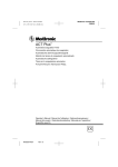
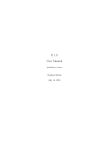
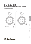
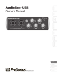
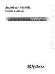
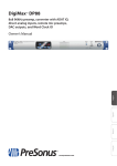
1
Controls and Connections Hookup Calibration Overview ® www.presonus.com Getting Started Owner’s Manual Technical Information Central Station Plus Central Station Plus Important Safety Instructions The exclamation point within an equilateral triangle is intended to alert the user to the presence of important operating and maintenance (servicing) instructions in this manual. The lightning flash with arrowhead symbol within an equilateral triangle is intended to alert the user to the presence of uninsulated “dangerous” voltage within the product’s enclosure that may be of sufficient magnitude to constitute a risk of electric shock to humans. CAUTION: TO REDUCE THE RISK OF ELECTRIC SHOCK, DO NOT REMOVE THE COVER. NO USER-SERVICEABLE PARTS INSIDE. REFER SERVICING TO QUALIFIED PERSONNEL. CAUTION: To reduce the risk of electric shock, do not expose this appliance to rain and moisture. The apparatus shall not be exposed to dripping or splashing liquids and no object filled with liquids, such as vases, shall be placed on the apparatus. CAUTION: These service instructions are for use by qualified service personnel only. To reduce the risk of electric shock, do not perform any servicing other than that contained in the operation instructions. Repairs must be performed by qualified service personnel. 1. Read these instructions. 2. Keep these instructions. 3. Heed all warnings. 4. Follow all instructions. 5. Do not use this apparatus near water. 6. Clean only with dry a cloth. 7. Do not block any ventilation openings. Install in accordance with the manufacturer’s instructions. 8. Do not install near any heat sources, such as radiators, heat registers, stoves, or other apparatus (including amplifiers) that produce heat. 9. Do not defeat the safety purpose of the polarized or grounding-type plug. A polarized plug has two blades, with one wider than the other. A grounding-type plug has two blades and a third grounding prong. The wide blade and the third prong are provided for your safety. If the provided plug does not fit into your outlet, consult an electrician for replacement of the obsolete outlet. 10. Protect the power cord from being walked on or pinched, particularly at plugs, convenience receptacles, and the point where they exit from the apparatus. 11. Use only attachments/accessories specified by PreSonus. Controls and Connections 12. Use only with the cart, stand, tripod, bracket, or table specified by the manufacturer or sold with this apparatus. When a cart is used, use caution when moving the cart/ apparatus combination to avoid injury from tip-over. 13. Unplug this apparatus during lightning storms or when unused for long periods of time. 14. Servicing is required when the apparatus has been damaged in any way, such as if a power-supply cord or plug is damaged; or liquid has been spilled, or objects have fallen, into the apparatus; or if the apparatus has been exposed to rain or moisture, does not operate normally, or has been dropped. All PreSonus products in the USA should be serviced at the PreSonus factory in Baton Rouge, Louisiana. If your product requires a repair, contact [email protected] to arrange for a return-authorization number. Customers outside the USA should contact their local distributor. Your distributor’s contact information is available at www.presonus.com. 15. The apparatus shall be connected to a Mains power outlet with a protective grounding/earthing connection. 16. Where the Mains plug or an appliance coupler is used as the disconnect device, the disconnect device shall remain readily operable. EU Directives on the Protection of the Environment and Other Euro Stuff RoHS This product is compliant with the EU Directive 2011/65/EU for the Restriction of the use of Certain Hazardous Substances in Electrical and Electronic Equipment. No lead (Pb), cadmium (Cd), mercury (Hg), hexavalent chromium (Cr+6), PBB or PBDE is intentionally added to this device. Any traces of impurities of these substances contained in the parts are below the RoHS specified threshold levels. REACh This product is compliant with the European Union Directive EC1907/206 for the Registration, Evaluation, Authorization, and Restriction of chemicals (REACh) and contains none or less than 0.1% of the chemicals listed as hazardous chemicals in the REACh regulation. WEEE This symbol on the product or its packaging indicates that this product must not be disposed of with other waste. Instead, it is your responsibility to dispose of your waste equipment by handing it over to a designated collection point for the recycling of waste electrical and electronic equipment. The separate collection and recycling of your waste equipment at the time of disposal will help conserve natural resources and ensure that it is recycled in a manner that protects human health and the environment. For more information about where you can drop off your waste equipment for recycling, please contact your local city recycling office or the dealer from whom you purchased the product. CE This product complies with the European Union Council Directives and Standards relating to electromagnetic compatibility EMC Directive (2006/95/EC) and the Low Voltage Directive (2004/108/EC). Technical Information Owner’s Manual INTRODUCTION — 1 PART II: REFERENCE — 16 1.0 Getting Started — 2 5.0 Controls and Connections — 16 Connect the CSR-1 to Your Central Station — 3 1.4 Connecting Monitor Speakers — 3 5.1.1Talkback — 16 5.1.2Headphones — 16 5.1.3 Cue/Main Select — 17 5.1.4Meter — 17 1.5 Using the Digital Input — 4 1.6 Using the Headphones and Talkback System — 5 5.1.5 Passive Speaker Control — 18 5.2 Back Panel Layout — 18 5.2.1Power — 18 2.0Overview — 6 5.2.2 Digital Inputs (24-bit/192 kHz) — 19 2.1 What’s In the Box — 6 2.2 Front Panel Layout — 16 5.2.3 Speaker Outputs L/R (A, B, and C) — 19 Features — 7 2.2.1 Summary of Features — 7 5.2.4 Line Outputs — 19 3.0 Calibrating Your Central Station — 8 5.2.5 Analog Inputs — 20 3.1 Calibrating the Meter — 8 5.2.7 Talkback Section — 20 3.2 Calibrating the Input Sources — 8 5.2.6 Console Remote Control — 20 5.3 3.3 Calibrating Speaker Levels — 9 3.3.1 Maximum Loudness Reference — 10 3.3.2 85 dB SPL Standard Reference — 11 4.0 Sample Hookup Diagrams — 13 4.1 Separate Control Room and Recording Room — 13 4.2 Mixdown / Mastering Setup — 15 Overview 1.3 5.1 Calibration Connect Input Sources — 2 CSR-1: Central Station Remote (optional) — 21 Hookup 1.2 5.3.1 CSR-1 Controls — 21 6.0 Technical Information — 22 6.1 Frequently Asked Questions — 22 6.2 Troubleshooting — 23 6.3 Specifications — 24 Controls and Connections Connect Power — 2 6.4 Block Diagram — 27 6.5 Remote DB15 Cable Pin-out — 28 6.6 PRESONUS LIMITED WARRANTY — 29 Technical Information 1.1 Getting Started Table of Contents iv Owner’s Manual Getting Started INTRODUCTION Overview Thank you for purchasing the Central Station Plus, the ultimate monitoring and communications system for recording studios. The Central Station uses highgrade components to ensure optimum performance that will last a lifetime and features a purely passive signal path for ultimate sonic performance. It provides talkback; speaker switching; input-source switching; two loud, clear headphone amplifiers; and a pair of line-level Cue and Main outputs to feed a headphone-distribution system. Best of all, the included CSR-1 Central Station Remote allows you to control these features remotely! Technical Information Controls and Connections Sample Hookup Diagrams Calibration We encourage you to contact us at 1-225-216-7887 with any questions or comments you may have regarding your PreSonus Central Station Plus system. PreSonus Audio Electronics is committed to constant product improvement, and we value your suggestions highly. We believe the best way to achieve our goal of constant product improvement is by listening to the real experts, our valued customers. We appreciate the support you have shown us through the purchase of this product. We are confident that you will enjoy your Central Station Plus! 1 1 1.1 Central Station Plus Getting Started Connect Power 1.0 Getting Started Getting Getting Started Started 1.1 Connect Power Before connecting a power supply to the Central Station, ensure that the power supply meets the input-voltage requirements of the region or country where you are using it. PreSonus only supports the power supply that is shipped with your Central Station. If it does not meet your requirements, or you wish to purchase an additional power supply, please contact your local dealer or distributor. Overview Calibration 1. “Zero” the Main, Cue, Aux In, and Phones level knobs by turning them fully counterclockwise. If you have speakers or other gear connected to the Main L/R outputs, turn them all the way down and make sure that the amplifier is powered off. Hookup 2. Connect the included power supply to the Central Station’s power-input connector and to the appropriate wall socket. Because of its passive circuitry, it is designed to be left on for long periods of time. Many manufacturers make power-relay systems that send power to blocks of outlets at different times so that your gear is instantly turned on and off in the correct order with the flip of a single switch. If you are uncomfortable leaving your equipment powered on all the time, these products are excellent solutions. 1.2 Connect Input Sources 1. “Zero” the Main, Cue, Aux In, and Phones level knobs by turning them fully counterclockwise. Controls and Connections 2. Connect your primary audio source (such as an audio interface or mixer main outputs) to the left and right TRS 1 inputs on the back of your Central Station. 3. [Optional]: Connect your secondary audio source (such as a CD or MP3 player) or cue audio source (such as the auxiliary outputs of your interface or mixer) to the left and right TRS 2 inputs on the back of your Central Station. 4. [Optional]: Connect a third source (such as a turntable or tone generator) to the left and right Aux (RCA) inputs. Technical Information Note: Turntables require a phono preamp that applies a special (RIAA) EQ curve. Most turntables do not have a phono preamp built in, and the Central Station does not supply one, so you may have to purchase a phono preamp from a local retailer. 2 Owner’s Manual 1.3 Getting Started 1 Connecting the CSR-1 to your Central Station 1.3 Connecting the CSR-1 to your Central Station Getting Getting Started Started 1. Connect one side of the included DB15 cable to the back of the CSR-1 and the other side to the Console connection on the back of your Central Station. Please note that the DB15 cable has a proprietary pin-out; it looks like a standard VGA cable but is wired differently. If you require a replacement cable, you will need to order it from www.PreSonus.com. 2. Press the Activate button on the back of your Central Station. When the CSR-1 is properly communcating with your Central Station, the Active light to the left of the Main Volume control on the CSR-1 will illuminate blue. Overview Once the CSR-1 is connected and activated, it will disable the Main Volume control on the front panel of your Central Station; use the Main Volume control on your CSR-1 instead. Connecting Monitor Speakers 1. Turn off all powered monitors and power amps before connecting cables. 2. Connect your powered control-room monitors (or power amp) to Speaker Output A. 3. [Optional] Connect your secondary control-room monitors (or power amp) to Speaker Output B. Controls and Connections Hookup 4. [Optional] Connect your subwoofer or tertiary control-room monitors (or power amp) to Speaker Output C. Because Speaker Output C can be enabled concurrently with either Speaker Output A or Speaker Output B, we recommend that you connect this output to your subwoofer for 2.1 mixing. 5. Turn the following controls completely counterclockwise: Talkback Mic Level, Headphone Level, Output Level, Aux In Level, and Main Output Level. 6. Using a flat-head screwdriver, turn the speaker trims for all passive speaker outputs completely counter-clockwise. Technical Information 1.4 Calibration All buttons on the CSR-1 correspond directly to, and control, their counterparts on the Central Station. 7. Power on your main input source (such as an audio interface or mixer). 8. Turn the volume of your main input source all the way down. 9. Power up your Central Station by connecting the power supply to the rear of the unit and to an AC outlet or power strip. 3 1 1.5 Central Station Plus Getting Started Using the Digital Input 10. Power up your power amp or powered monitors and turn the level controls to 0 dB. Getting Getting Started Started 11. Press the Speaker Output A button. 12. Press the TRS 1 button in the Main Input Select section. 13. Play a stereo signal from your main input source and slowly turn the volume on the source to unity gain. You may need to consult the manufacturer of your main input source if you do not know the position of unity gain. Overview 14. Slowly turn the Main Level control on your CSR-1 fully clockwise until you hear signal in the monitors. Adjust the sound to a comfortable listening level. If the listening level of your monitors cannot be adjusted low enough with the Central Station, do not lower the volume of your main input source; instead, lower the level control on your power amp or powered monitors until the level is satisfactory. 15. Press the Speaker Output B button and repeat steps 12 through 14. If the set of monitors connected to one output is louder than the other set of monitors, adjust the power amp for the louder set or use a flat-head screwdriver to adjust the level of the louder set of monitors to match the quieter set. Toggle between Speaker Output A and Speaker Output B to verify that the levels match. Calibration 16. If you have connected a third set of monitors to Speaker Output C, repeat the process in step 15 for this set of monitors. If you have connected a subwoofer to Speaker Output C, repeat steps 12 through 14 while Speaker Output A is concurrently engaged, and adjust the volume of your subwoofer until you have a balanced 2.1 mix. 1.5 Using the Digital Input Hookup 1. Using a digital S/PDIF cable, connect the S/PDIF coaxial (RCA-style) output from your DAW, CD player, audio interface, or other digital device to the S/PDIF coaxial input on the Central Station. 2. Press the Digital button on the CSR-1’s Main Input Select section. 3. Press the S/PDIF button in the CSR-1’s Digital Input section. 4. Press the Speaker Select button for your desired monitors. 5. Play stereo audio from an S/PDIF source. The Central Station will automatically detect and lock to the sampling rate of the source device. Controls and Connections 6. Adjust the Main Level control to desired level. Follow the same instructions for Toslink devices. Toslink is a type of stereo, digital, optical S/PDIF connection found on many consumer audio devices. While the Toslink jack is similar to the ADAT Lightpipe connector, it is not an ADAT port. Technical Information 4 Owner’s Manual Getting Started 1 Using the Headphones and Talkback System 1.6 Using the Headphones and Talkback System Getting Getting Started Started 1. Turn the Phones and Mic levels fully counterclockwise. 2. Press the Phones 1 control knob so that the Cue light, rather than the Main light, is illuminated. 3. Press the TRS 1 button in the Cue Input Select section. 4. Connect a pair of headphones to the Phones 1 output. 5. Play a stereo signal from the source connected to the TRS 1 input. Overview Overview 6. While wearing headphones, slowly turn the Phones level clockwise until the listening level is comfortable. Controls and Connections Sample Hookup HookupDiagrams Calibration 7. Press the TB (Talkback) button and talk into the Mic Input grille on the front panel, while slowly turning the Mic Input Level knob clockwise until the talkback microphone is at a comfortable level. Technical Information 1.6 5 Central Station Plus 2Overview 2.1 What’s in the Box 2.0Overview Getting Started 2.1 What’s In the Box In addition to this manual, your Central Station package contains the following: Overview Overview •• Central Station Studio Control Center Calibration •• CSR-1 Central Station Remote •• Central Station Power Supply Hookup •• CSR003 3 Meter Cable for CSR-1 Controls and Connections •• •• PreSonus Warranty Card Technical Information 6 Owner’s Manual Overview2 Features2.2 Features The Central Station features high-quality analog circuitry and digital conversion. Three sets of stereo analog inputs enable the Central Station to accept a wide variety of sources. Its S/PDIF coax and Toslink (optical) digital inputs provide up to 24-bit, 192 kHz digital-to-analog conversion, and the converters deliver over 115 dB of dynamic range. Each of the three sets of balance monitor outputs has a passive trim pot. The monitoring section provides Mute, Dim, and Mono controls, in addition to separate main line-level output and a set of cue outputs that can feed headphone amplifiers. Overview Overview The main audio path uses no amplifier stages and has no op amps or active integrated circuits (ICs), as these types of components typically add noise, color, and distortion and produce a “pinched” sound. Eliminating distortion also helps reduce ear fatigue. Calibration Calibration Signal routing is achieved using 34 sealed, mechanical relays (instead of active ICs). Extraneous electronics are hard-wire bypassed, helping maintain a minimal signal path. Using relays ensures the most transparent signal path and maximizes dynamic range, frequency range, and headroom, while minimizing noise and coloration. The Central Station uses the highest-quality passive components, including military-grade, 1% tolerance, metal-film resistors; multi-element potentiometers; and durable connectors to deliver the highest sonic performance. Summary of Features •• Passive audio path; no op-amps or ICs •• Three sets of stereo analog inputs lets you switch between sources Sample Hookup HookupDiagrams •• Two sets of stereo digital inputs (coax and optical) •• Three sets of stereo speaker outputs with Speaker Select switches and recessed trim pots for each output •• Cue section with input-select switch and output-level control •• Main section with input-select switch, aux-input level control, output-level control, mute, dim, and mono switches Controls and Connections •• Talkback microphone system with onboard mic, external microphone input, and footswitch input •• Dual 30-segment, fast acting, peak-hold LED metering with Clear Peak switch and calibration •• High-definition, 24-bit, 192 kHz D/A converter with 115 dBu dynamic range •• Remote controllable via Central Station Remote (CSR-1) Technical Information 2.2.1 Getting Started 2.2 7 Central Station Plus 3Calibration 3.1 Calibrating the Meter 3.0 Calibrating Your Central Station Getting Started In order to create the most accurate mixing environment, it is important to calibrate each component in your system so that the metering and output levels match. 3.1 Calibrating the Meter The meters on your Central Station can (and should) be calibrated to match the meters in your DAW or on your mixer. Overview 1. Send a 1 kHz, 0 dBu sine-wave test tone to any input on your Central Station. Select the input you are using in the Main Input Select section on the front panel. In a computer-based recording system, this can be accomplished by creating an audio track in the software and importing a test-tone audio file, or by using a tone-generator plug-in. 2. Decrease the volume of the test-tone channel until the meter on your DAW or on your mixer’s main output reads -18 dB. Calibration Calibration 3. Press and hold the calibration button on the front panel of the Central Station (it’s the bottom button in the Meter section) for two seconds. The meter will recalibrate to read -18 dBfs/0 dB. 4. Raise the level of the test tone until the meter on your DAW’s master section reads 0 dB, and check to see whether the Central Station meter shows a redlined signal, which indicates that the signal is overloading (clipping) the input. 5. For more accurate calibration, raise or lower the test-tone level plus or minus 0.10 dB and repeat steps 2 through 4. 6. Note that the calibration range of the Central Station is approximately ±12 dB. Hookup 3.2 Calibrating the Input Sources 1. “Zero” the Main, Cue, and Phones level knobs by turning them fully counterclockwise. 2. Turn the outputs of your primary audio source (connected to TRS1) to their lowest setting. Controls and Connections 3. Remove all effects processors (such as EQs, compressors, and reverbs) from the signal path and play a clean 0 dB test tone (for example, a 1 kHz sine wave) through the outputs of your primary audio source. 4. Select TRS 1 as the Main Source and begin turning up the outputs of your primary audio source to their unity-gain setting or until the Central Station meter’s red 0 dBVU LED comes on. If you are not able to reach unity gain (or come very close to it) without the red 0 dBVU LED coming on, ensure that you have properly calibrated the meter. Repeat the steps in manual Section 3.1 and then repeat this step. Technical Information “Unity gain” is the level or setting at which the signal level is neither boosted nor attenuated, and it is usually marked by a “0” on the audio device’s level fader or knob. In many digital interfaces and other digital devices, the device’s maximum level is also its unity-gain setting. Please consult your audio device’s user manual or the manufacturer’s Web site for more information on its levels and adjustments. Aux/Phono only: Do not adjust the output level of your audio device if 8 Owner’s Manual Calibration3 Calibrating Speaker Levels 3.3 Getting Started it is set at its optimum or maximum level. Instead, turn on your phono preamp (if necessary) and increase the Aux Input Level knob, starting from -80, until the red 0 dBVU meter just comes on (and no higher). 5. Repeat steps 1 through 3 for the secondary/cue audio sources connected to the TRS 2 and Aux inputs. Calibrating Speaker Levels Overview The main purpose of speaker calibration is to ensure that a specific, metered audio level (typically 0 dBVU) equals a certain acoustic level (measured in dB SPL) in your studio environment. Depending upon the method and reference levels used during calibration, proper calibration can help reduce unwanted noise, minimize the risk of damage to your speakers and your ears, maximize the reference capabilities of different speaker types, and ensure that you and your listeners are hearing the audio as the engineer intended. All calibration methods, including those discussed in this manual, have something in common: test tones. The most commonly used test tones are 100 Hz, 1 kHz, and 10 kHz sine waves; 40 to 80 Hz and 500 Hz to 2.5 kHz, bandwidth-limited pink noise; and 20 Hz to 20 kHz pink noise and white noise. Test-tone CDs can be purchased from your local music retailer or downloaded off the Internet from a variety of Web sites. As a less technical and more subjective alternative, the chorus of your favorite modern, commercially produced song can be substituted for full-bandwidth pink noise. Controls and Connections Hookup When calibrating reference monitors in a studio, the acoustic level, or soundpressure level (SPL), should be measured from the proper mix position. Ideally, this position will place the monitors at ear-level while you are seated at your mixing desk. The monitors should be equidistant from your ears and from each other, forming an equilateral triangle, with your head at the point. The SPL meter should be held at arm’s length, with the microphone pointed at the center point between the left and right speakers, angled at 45 degrees to ensure an accurate reading. You should also calibrate the left and right monitors independently: pan the test tone hard left, calibrate the left monitor, and then repeat for the right channel. Calibration Calibration There are many different methods for calibrating studio monitors. The methods discussed here are not the only methods. Various studio environments with different gear, clientele, and audio mixes may ultimately benefit more from other calibration methods. When monitoring systems are calibrated using the same method, each system should generate the same acoustic level when given the same input source. This is especially important when referencing your mix on different monitoring systems (such as toggling between Speaker A and Speaker B for comparison). In an incorrectly calibrated studio, the acoustic level will “jump” when toggling among the different systems, resulting in an inaccurate perception of the consistency of your mix across different types of speakers. When calibrated properly, playing audio through Speaker A, then switching to Speaker B, should not cause a change in volume. Switching monitors usually results in a slight tonal variation due to the different acoustic properties of the monitoring systems. The purpose of a speaker-switching system like the Central Station is to enable you to create a mix that sounds great on your car radio and home stereo, as well as in your studio. Technical Information 3.3 9 3Calibration 3.3 Calibrating Speaker Levels 3.3.1 Central Station Plus Maximum Loudness Reference Getting Started This method of speaker calibration references a 0 dBVU meter reading to the loudest level you want. This is the least technical, most subjective method and is good for environments where there is such a thing as “too loud” (such as an apartment, school, or OSHA-regulated venue), or when a certain level of “louder” needs to be attainable (for example, for entertaining guests at parties, clubs, and other live venues). 1. “Zero” the Speaker, Main, Cue, and Phones levels by turning them fully counterclockwise. 2. Select the TRS1 Main Source and Speaker A selections. Overview 3. Turn your primary monitoring system’s (connected to Speaker A) input level to its lowest setting. Consult your monitor system’s user manual or manufacturer’s Web site for more information about adjusting the input or amplification level. 4. Remove all effects processors (such as EQs, compressors, and reverbs) from the signal path and play 500 Hz through 2.5 kHz, bandwidth-limited pink noise at 0 dB through your primary audio-source outputs. If you are calibrating a subwoofer, use 40 Hz to 80 Hz, bandwidth-limited pink noise. Calibration Calibration You should not hear the test tone. If you do, turn down the speaker output and repeat Step 1. 5. If you are using an SPL meter, pan the test tone so that it only plays in the left speaker (hard left). NOTE: When both speakers play simultaneously, the overall SPL will increase by about +3 dB. To account for this, subtract 3 dB when calibrating the left and right channels. (For example, if your overall acoustic level cannot exceed 90 dB SPL, calibrate each speaker to reach only 87 dB SPL.) Hookup 6. Turn the Main level knob on your Central Station to Unity Gain by turning it fully clockwise. Controls and Connections 7. In the Passive Speaker Control section, locate the Speaker Trim controls for L/R Output A. Using a flat-head screwdriver, turn the trim control for the left channel completely counter-clockwise. Next, slowly turn Speaker Output A’s passive control clockwise. You should begin hearing the test tone playing through your primary speakers. If the acoustic level reaches your desired maximum level (as measured by your ears or with an SPL meter), stop increasing the speaker level and skip step 8. In most cases, you should not reach your maximum level yet. 8. Begin slowly increasing the input sensitivity (volume) of your primary monitoring system’s left speaker until the acoustic level of the test tone reaches the desired maximum SPL. 9. Repeat steps 4 through 8 for the right channel. Technical Information 10. If you are calibrating a monitoring system with independent subwoofer level control (such as a 2.1 or 2-way speaker system), repeat steps 4 through 8 for the subwoofer level. 11. Repeat steps 1 through 9 for the monitoring systems connected to Speaker Outputs B and C. 10 Owner’s Manual Calibration3 Calibrating Speaker Levels 3.3 NOTE: dBFS means “decibels full scale” and is associated with decibel amplitude levels in digital systems where there is a finite maximum available level (such as in standard PCM encoding). The maximum level possible is referred to as “0 dBFS.” In digital systems with analog outputs (such as digital interfaces), the analog-to-digital and digital-to-analog converters (ADCs and DACs) are referenced so that 0 dBFS equals a certain amount of analog voltage. (For example, a 0 dBFS tone playing at unity gain from a FireBox measures +18 dBu, while a 0 dBFS from a FireStudio Project at unity gain measures +10 dBu.) It is important to know your digital devices’ 0 dBFS reference to prevent clipping and to aid in proper calibration. 1. “Zero” the Speaker, Main, Cue, and Phones levels by turning them fully counterclockwise. Calibration Calibration This method of speaker calibration references a specific “standard” meter reading to a certain acoustic level. This is the most technical, least subjective method and is good for studios where a specific type of audio is produced or where an industry-standard audio level exists (such as for film or broadcast). One of the most common calibration standards (and the one presented here) is -20 dBFS referenced to 85 dB SPL. Overview 85 dB SPL Standard Reference 2. Select the TRS1 Main Source and Speaker Output A. Hookup 3. Turn your primary monitoring system’s (connected to Speaker Output A) input level to its lowest setting. Consult your monitor system’s user manuals or the manufacturer’s Web site for more information about adjusting the input or amplification level. 4. Remove all effects processors (EQs, compressors, reverbs, etc.) from the signal path and play 500 Hz to 2.5 kHz, bandwidth-limited pink noise at -20 dBFS through your primary audio source outputs. If you are calibrating a subwoofer, use 40 Hz to 80 Hz, bandwidth-limited pink noise. Controls and Connections You should not hear the test tone. If you do, turn down the speaker volume and repeat Step 1. 5. Pan the test tone so it only plays in the left speaker (hard left). 6. Turn the Main level knob to Unity Gain by turning it fully clockwise. 7. In the Passive Speaker Control section, locate the Speaker Trim controls for L/R Output A. Using a flat-head screwdriver, turn the trim control for the left channel completely counter-clockwise. Next, slowly turn Speaker Output A’s passive control clockwise. You should begin hearing the test tone playing through your primary speakers. Increase the level until the SPL meter reads 85 dB. In most cases, you should not reach 85 dB SPL yet. 8. Begin slowly increasing the input sensitivity (volume) of your primary monitoring system’s left speaker until the acoustic level of the test tone reaches 85 dB SPL. 9. Repeat steps 4 to 8 for the right channel. 11 Technical Information 3.3.2 Getting Started 12. Test: Play audio through Speaker A only. Without adjusting any of the Central Station’s levels, toggle Speaker A off and Speaker B on. You may hear a slight tonal variance due to the different acoustic properties of the monitoring systems but the loudness should remain the same. If the loudness varies drastically, you may wish to repeat this calibration procedure from step 1. 3Calibration 3.3 Calibrating Speaker Levels Central Station Plus Getting Started 10. If you are calibrating a monitoring system with independent subwoofer level control (such as a 2.1 or 2-way speaker system), repeat steps 4 to 9 for the subwoofer level. Repeat steps 1 through 10 for the monitoring systems connected to Speaker Outputs B and C. 11. Test: Play audio through Speaker A only. Without adjusting any of the Central Station’s levels, toggle Speaker A off and Speaker B on. You may hear a slight tonal variation due to the different acoustic properties of the monitoring systems, but the loudness should remain the same. If the loudness varies drastically, you may wish to repeat this calibration procedure from step 1. Overview Calibration Calibration Hookup Controls and Connections Technical Information 12 Owner’s Manual Sample Hookup Diagrams 4 Separate Control Room and Recording Room 4.1 Getting Started 4.0 Sample Hookup Diagrams The Central Station is an extremely flexible tool and can be used in all stages of the recording and music-production process. There are many ways to use and set up your Central Station. Here are two typical setups. Separate Control Room and Recording Room Sample Hookup Diagrams Calibration Overview Here is a typical recording setup where the band or artist is in another (soundproof) room while the recording engineer and producer are in the control room, listening to the recording on speakers. Controls and Connections Headphones to check song Separate Control Rooms and Recording Room continues next page... 13 Technical Information 4.1 4 4.1 Central Station Plus Sample Hookup Diagrams Separate Control Room and Recording Room (continued) Separate Control Room and Recording Room (continued) 4.1 Getting Started FIRESTUDIO PROJECT (Computer Interface) SPDIF Digital Output or Main L/R Analog Output CD Player CSR-1 Optional Remote Control mic Overview RCA Analog Output or TOSLINK Output Calibration POWER Power 12-18VDC 10Watts Sample Hookup Diagrams DAT Recorder Record to external recorder Powered Speakers A Speaker C (Powered Subwoofer) Controls and Connections Power Amplifier Talkback Foot switch Technical Information Passive Speakers B Headphone Distribution Amp 14 14 Owner’s Manual Sample Hookup Diagrams 4 Mixdown / Mastering Setup 4.2 Mixdown / Mastering Setup Overview Headphones to check song FIRESTUDIO PROJECT (Computer Interface) SPDIF Digital Output or Main L/R Analog Output Getting Started Here is a typical mixdown or mastering setup in which the Central Station’s 24-bit, 192 kHz digital-to-analog converter is being used to compare the music being created (mixed or mastered) with a commercial CD. CD Player CSR-1 Remote Control mic Calibration RCA Analog Output or TOSLINK Output Sample Hookup Diagrams POWER Power 12-18VDC 10Watts Powered Speakers A Controls and Connections DAT Recorder Record to external recorder Speaker C (Powered Subwoofer) Power Amplifier Talkback Foot switch Technical Information 4.2 Passive Speakers B Headphone Distribution Amp 15 5 5.1 Central Station Plus Controls and Connections Front Panel Layout PART II: REFERENCE Getting Started 5.0 Controls and Connections Front Panel Layout 5.1.1 Talkback Overview 5.1 Calibration Sample Hookup Diagrams 5.1.2 •• Talkback microphone. The built-in talkback microphone is an electret condenser microphone and is positioned just below the Talkback Level knob. •• Talkback Level. Adjusts the gain level of the talkback microphone preamplifier +15 to +55 dB. •• Talk. Engages and disengages the talkback-microphone preamplifier. The talkback microphone routes to the Cue bus only. Engaging the talkback microphone automatically engages the Dim feature for both the Main and Cue buses. Headphones •• Phones. Connect headphones to the Central Station’s two headphone amplifiers. Controls Controls and and Connections Connections •• Dual-function Level Control. When turned, the knob adjusts the level of the associated headphone amplifier. When pressed, it switches between Main and Cue audio inputs as sources for the corresponding headphone amplifier. The Talkback Microphone will not be patched to the headphones unless “Cue” has been selected as the source. Technical Information 16 Owner’s Manual 5.1.3 Controls and Connections 5 Front Panel Layout 5.1 Cue/Main Select Overview Getting Started The Central Station comes equipped with separate Cue and Main signal paths. The Cue signal path includes the talkback-microphone signal and sends this signal to the recording artist via an external headphone amp or the two onboard headphone amps. The Main signal path is intended for the control room and does not include the Talkback signal. •• Cue Output Level Control. Adjusts the overall output level of the Cue audio path. •• Input Select Buttons. Determing the sources for the Cue or Main Audio Paths Calibration •• TRS 1. Patches the analog TRS1 input to the Cue or Main audio path. TRS 2. Patches the analog TRS2 inputs to the Cue or Main audio path. Digital. Patches the currently selected Digital input (Toslink or S/PDIF) to the Cue or Main audio path. Aux. Patches the Aux input to the Cue or Main audio path. Sample Hookup Diagrams •• Digital Input. Selects the S/PDIF or Toslink input as the digital source for the Cue and Main audio paths. •• Aux Input Level Control. Adjusts the overall input level of the Aux input. Meter The Central Station comes equipped with dual, independent, tricolored, 30-segment LEDs for metering the audio signal. The scale is represented in dBfs and dBu for use with analog outboard equipment and digital audio workstations, sound cards, and other digital systems. •• lear Peak. The meters on the Central Station have C a Peak Hold feature so that the red clip LED will remain on once the signal has clipped. Pressing the Clear Peak button will reset the clip light. •• Calibrate. You can calibrate the meters on your Central Station to match the metering on other equipment. Audio-software metering can vary depending on the software, and it is usually desirable to calibrate the meters on your Central Station to match the metering in your audio software. For detailed instructions on calibrating the meters on your Central Station please refer to Section 3.1. Technical Information 5.1.4 Controls Controls and and Connections Connections •• •• •• 17 5 5.2 Central Station Plus Controls and Connections Back Panel Layout 5.1.5 Passive Speaker Control Getting Started Speaker Select (A, B, and C). These buttons activate stereo speaker linelevel outputs A, B, or C. Speaker Select A and B cannot be enabled at the same time. Speaker Select C can be enabled concurrently with either A or B. Because of this, Speaker C is typically used for a subwoofer. •• Speaker Trim Left/Right (A, B, and C). These recessed potentiometers are used to adjust each speaker output level separately. Use a small flat-head screwdriver to adjust this control. •• Main Level. This multi-element potentiometer adjusts the overall volume level of the Main audio path. •• Mute. Mutes the Main audio output. •• Dim. Attenuates the Main audio output by approximately -16 dB. •• Mono. Combines the left and right signals to check mono compatibility and phase cancellation. Overview •• Calibration Sample Hookup Diagrams Back Panel Layout 5.2 POWER 12-18VDC 10Watts 5.2.1 Power Controls Controls and and Connections Connections POWER Technical Information 12-18VDC 10Watts 18 This is the connection for the Central Station’s proprietary external power supply. Only this power supply should be used with your Central Station. Replacement power supplies can be purchased directly from PreSonus or from a musical-equipment retailer. Owner’s Manual Controls and Connections 5 Back Panel Layout 5.2 Digital Inputs (24-bit/192 kHz) Getting Started 5.2.2 Central Station automatically reads and locks to the sample rate of the incoming digital stream and can receive and lock to sample rates of 44.1, 48, 96, and 192 kHz. Both of these digital inputs are designed for the S/PDIF stereo digital format. Overview Coaxial connectors are most commonly used for S/PDIF. While S/ PDIF coaxial connections may resemble the analog RCA connection on consumer audio products, these connections should not be confused. In recent years, Toslink optical connections have gain popularity, especially in consumer-grade audio products like DVD players. As with the professional AES/EBU format, a single cable carries both channels of the stereo audio signal. •• Toslink. Accepts a stereo S/PDIF digital input signal via an optical connector. •• S/PDIF. Accepts a stereo S/PDIF digital signal via a coaxial (RCA-type) connector. Speaker Outputs L/R (A, B, and C) Calibration 5.2.3 Sample Hookup Diagrams These three stereo pairs of left (L) and right (R), line-level, ¼” balanced TRS outputs can connect to powered monitors or to power amps for passive speakers. Only balanced cables should be used when connecting the Central Station to your monitors. Because of the Central Station’s passive circuitry, using unbalanced cables can reduce the output level and can introduce noise into your system. 5.2.4 Line Outputs Controls Controls and and Connections Connections These outputs are ideal for connecting external headphone-distribution systems or external mastering units. Again, only balanced cables should be used when connecting your Central Station to these devices. Because of the Central Station’s passive circuitry, using unbalanced cables can reduce the output level and can introduce noise into your system. •• Main (L/R). Connect this stereo pair of left (L) and right (R), line-level, ¼” balanced TRS outputs to a recording device. There is no attenuator (volume control) on this output. Technical Information •• Cue (L/R). Connect this stereo pair of left (L) and right (R), line-level, ¼” balanced TRS outputs to a headphone-distribution amplifier. The front-panel Cue Output Level adjustment controls volume level. 19 5 5.2 Central Station Plus Controls and Connections Back Panel Layout 5.2.5 Analog Inputs Getting Started These inputs are for your audio sources (mixer, audio interface, CD player, etc.). Only balanced cables should be used when connecting the balanced TRS inputs of your Central Station to these devices. Because of the Central Station’s passive circuitry, using unbalanced cables can reduce the output level and can introduce noise into your system. •• TRS 1 (L/R). Left and right, line-level, balanced ¼” TRS inputs. Overview •• TRS 2 (L/R). Left and right, line-level, balanced ¼” TRS inputs. •• AUX (L/R). Left and right, line-level, unbalanced RCA TS inputs. 5.2.6 Console Remote Control Calibration •• Activate button. Activates optional CSR-1 remote control. When the Activate button is depressed, the Main Level control on the Central Station is bypassed. •• Console Remote Connection. This proprietary DB15 15-pin connector is for the optional CSR-1 Central Station remote control. See Section 5.3 for complete instructions. Sample Hookup Diagrams 5.2.7 Talkback Section •• Pedal. Unbalanced ¼” TS connector for use with a momentary footswitch. Controls Controls and and Connections Connections •• Activate button. Activates the external microphone input to be the source for the Talkback system and bypasses the onboard Central Station microphone. Please note: the onboard CSR-1 microphone is always active regardless of whether or not the external mic is activated. •• External Microphone Input. This XLR connector feeds an onboard microphone preamp for use with an external Talkback mic. This preamp does not supply phantom power so only dynamic microphones can be used. Technical Information 20 Owner’s Manual 5.3 Controls and Connections 5 Central Station Remote 5.3 CSR-1: Central Station Remote Getting Started The Central Station Remote Control (CSR-1) connects to the rear of the Central Station via a proprietary DB15 cable (included with the Central Station Plus) to control Volume, Talkback, Mute, Input Source Switching and Speaker Output Switching functions. Allowing you to keep the Central Station in your rack with your gear and use the CSR-1 on your desktop for ultimate control and flexibility. This section will familiarize you with the CSR-1 control functions. 5.3.1 Overview Please Note: Your Central Station Plus system can be used with or without the CSR-1 connected. When using your Central Station without the remote, simply control all functions from the main unit.. CSR-1 Controls Below is a diagram of the CSR-1 controls. Each control corresponds directly to the same control on the Central Stration. All CSR-1 functions control their corresponding Central Station functions, except for the Talkback Mic level. The Central Station and CSR-1 retain independent control over their respective onboard talkback microphones. Digital: Patches the current digital input selection to the Mains. Aux: Patches the analog Aux input to the Mains. Talk Button: Engages / disengages the talkback microphones on both the CSR-1 and the Central Station. Because both microphones remain active when the CSR-1 is connected, it is recommended that you turn the Talkback Mic level all the way down on the main unit when you are not using it. Calibration Speaker Select A,B,C: Activates the stereo speaker line outputs. Mute: Mutes the Main Audio Output. Dim: Attenuates the Main audio output by -16 dB. Mono: Sums the left and right signals. Main Level: Adjusts the overall volume level of the Main output. Active Light: When illuminated, this light alerts you that your CSR-1 has Main Volume Control. Talkback Mic and Level: The Talkback Mic Level adjusts the gain for the built-in eletret condenser microphone on the CSR-1 only. Because the Talkback Mic in the CSR-1 remains active when an external microphone is connected, we recommend you turn the Mic Level all the way down when using an external talkback microphone. 21 Sample Hookup Diagrams TRS2: Patches the analog TRS2 input to the Mains. Passive Speaker Controls Controls Controls and and Connections Connections TRS1: Patches the analog TRS1 input to the Mains. Digital Input Select: Selects the S/PDIF or Toslink input as the digital source for the Cue and Main audio paths. Technical Information Input Select Buttons 6 6.1 Technical Information Frequently Asked Question Central Station Plus 6.0 Technical Information Getting Started 6.1 Frequently Asked Questions Why can’t I hear the talkback microphone? Overview •• Only headphones with a Phones Source of “Cue” can hear the talkback microphone. •• Connect and/or calibrate your talkback microphone according to Section 1.5. •• Verify your external mic does not require phantom power. •• If you are not using an external microphone, disconnect anything connected to the XLR input. Why do I see levels on the LED meter but not hear anything through the speakers? Calibration Sample Hookup Diagrams •• The LED meter only measures the Central Station’s input, not its output. •• Connect and calibrate your speakers according to Sections 1.3 and 3.3. •• Ensure that the correct Speaker Select button is lit and that its Speaker Level Adjust knob is turned up. •• Disengage the Talk, Mono, Mute, and Dim buttons. Then slowly turn up the Main Level knob. •• Move your speakers to a different output to verify the outputs are functioning properly. •• Connect the input source directly to your speakers to verify the speakers are functioning properly. I have everything turned all the way up, but my speakers still aren’t loud enough. What gives? •• The Central Station is not an amplifier, so please do not try to use it as one. •• The only inputs with preamp gain are the Aux/ Phono and external microphone inputs. •• The only outputs with gain are the headphone amplifiers. Controls and Connections Why doesn’t the Main Level knob control the Main Outs? •• Technical Information 22 The Central Station was not designed to function that way. Connect the Main Outs to a device that should receive an unprocessed signal, such as a CD recorder. Owner’s Manual Technical Information 6 Troubleshooting6.2 Troubleshooting Getting Started Please note that many technical issues can arise when connecting different components in a studio environment. PreSonus only provides support for issues directly related to the Central Station Studio Control Center; we do not provide support for non-PreSonus hardware and software. It may be necessary to contact the manufacturers of your other studio equipment to obtain additional technical support. Please check www.presonus.com regularly for information, updates, and technical support. •• Turn the power off and then on by disconnecting and reconnecting your Central Station’s power cable. •• Check your connection cables and audio sources. •• Check your headphones and speakers. Calibration Check our Web site at www.presonus.com for answers to frequently asked questions and for troubleshooting techniques specific to the Central Station. Isolate the problem by disconnecting your input sources and monitor systems and testing them independently to ensure they are functioning properly. For technical assistance, visit our Web site at: www.presonus.com, call us at 1-225-216-7887 between 9 a.m. and 6 p.m. CST (GMT 06:00), or e-mail us at [email protected]. •• A brief description of what equipment and connections are being made to your Central Station. •• The desired application of your Central Station in your studio environment. •• Your Central Station serial number (located on the bottom of your unit). Controls and Connections When contacting technical support, please have the following information at hand: Sample Hookup Diagrams •• Overview If you experience any difficulty with your Central Station, please try the following before contacting PreSonus Customer Support: Technical Information 6.2 23 Central Station Plus 6 Technical Information 6.3Specifications 6.3 Specifications Getting Started Audio Inputs TRS1 & TRS2 Overview Type ¼” TRS Passive-Balanced Input Impedance 2-5Ω (depends on speaker load and trim) S/N Ratio >140 dB THD+N < 0.0005% (1 kHz @ 0 dBu) Frequency Response > 1 MHz Aux Calibration Type RCA Active-Unbalanced Input Impedance 8 kΩ S/N Ratio >115 dB (1 kHz @ 0 dBu, Unity gain) THD+N < 0.002% (1 kHz @ 0 dBu, Unity gain) Frequency Response 10 Hz-50 kHz, -0.5 dB Gain Range -90 to +20 dB Digital Sample Hookup Diagrams Type 75Ω RCA coaxial and Toslink optical DAC Dynamic Range 115 dB THD+N <0.0025% (1 kHz @ -0 dBfs) Maximum Output +18 dBu (Active Balanced) Bit Depth 24 Sample rates 44.1, 48, 88.2, 96, 176.4, and 192 kHz Controls and Connections Note: All input specifications (except Input Impedance) measured at Speaker A output, with Trim and Main Level set to maximum. Audio Outputs Speakers Technical Information Type ¼” TRS Passive-Balanced Type-Mono Activated ¼” TRS Active-Impedance Balanced Trim Range -90 dB to 0 dB Main Level Range -90 dB to 0 dB Dim Attenuation -16 dB 24 Owner’s Manual Technical Information 6 Specifications6.3 Type ¼” TRS Active-Balanced Output Impedance 51Ω Getting Started Main THD+N<0.0025% Frequency Response 10 Hz-50 kHz, -0.5 dB ¼” TRS Active-Impedance Balanced Output Impedance 51Ω THD+N < 0.003% (1 kHz @ 0 dBu) Frequency Response 10 Hz-50 kHz, -0.5 dB Gain Range -90 dB to 0 dB Dim Attenuation -16 dB (Talkback activated) Calibration Type Overview Cue Type ¼” TRS Active Stereo Maximum Output 150 mW/channel @ 60Ω load THD+N 0.015% (150 mW/channel @ 60Ω Frequency Response (±1.0 dB) 10 Hz-50 kHz Sample Hookup Diagrams Headphones Talkback Internal Microphone Type Electret Condenser Sensitivity -42 dB XLR Female Balanced Input Impedance 2.4 kΩ Frequency Response (±1 dB) 10 Hz to 40 kHz Maximum Gain 50 dB Gain Range +15 to +55 dB Technical Information Type Controls and Connections Mic Preamp 25 Central Station Plus 6 Technical Information 6.3Specifications Input Meters Getting Started Type 30-segment LED w/Peak Hold Range -48 dB to +18 dB (-66 dBfs to 0 dBfs) Accuracy Better than 0.25 dB Frequency Range 10 Hz-22 kHz Calibrate Range ±18 dB Power Supply Overview TypeExternal Power Input Voltage Range 12-18 VDC Power Requirements (continuous) 10W Physical Calibration Main Chassis Package Type 1U Dimensions 19 (W) X 1.75 (H) X 5.50 (D) inches Weight 5.0 lbs. Sample Hookup Diagrams As a commitment to constant improvement, PreSonus Audio Electronics, Inc., reserves the right to change any specification stated herein, at any time, without notification. Controls and Connections Technical Information 26 MIC LEVEL TALKBACK CUE LEVEL OUTPUT SWITCHING L L L Technical Information Controls and Connections Sample Hookup Diagrams Calibration Overview L L R L R L R L R L R L Getting Started PHONES CUE 2 1 SPEAKER C SPEAKER B SPEAKER A MAIN OUTPUT EXTERNAL DYNAMIC HEADPHONE SWITCHING MIC DIM L L L INTERNAL ELECTRET EXTERNAL ENABLE SPDIF DAC DIM MONO L L R R MUTE MASTER VOLUME FOOTSWITCH REMOTE TOSLINK COAX AUX L TRS 2 L R L L L 6.4 TRS 1 INPUT SWITCHING INPUT METERS Owner’s Manual Technical Information 6 Block Diagram 6.4 Block Diagram 27 6 6.5 Central Station Plus Technical Information Remote DB15 Cable Pin-out 6.5 Remote DB15 Cable Pin-out Getting Started Overview Twisted P1 Pin P2 Pin Number Number Pair Calibration 1-1 1-2 2-1 2-2 3-1 3-2 4-1 4-2 5-1 5-2 6-1 6-2 7-1 7-2 8-1 8-2 SHIELDS Sample Hookup Diagrams Controls and Connections Technical Information 28 5 10 4 9 3 8 2 7 14 15 12 13 11 1 6 NC 1 5 10 4 9 3 8 2 7 14 15 12 13 11 1 6 NC 1 Remote Function Right-High Send Right-High Return Level Right-Low Send Right-Low Return Level Left-High Send Left-High Send Left-Low Send Left-Low Send Remote Talkback Switch Remote Microphone Data (-) Data (+) +15VDC Ground Ground Owner’s Manual Technical Information 6 PreSonus Limited Warranty 6.6 Overview Calibration Sample Hookup Diagrams PreSonus Audio Electronics, Inc., warrants this product to be free of defects in material and workmanship for a period of one year from the date of original retail purchase. This warranty is enforceable only by the original retail purchaser. To be protected by this warranty, the purchaser must complete and return the enclosed warranty card within 14 days of purchase. During the warranty period, PreSonus shall, at its sole and absolute option, either repair or replace, free of charge, any product that proves to be defective on inspection by PreSonus or its authorized service representative. To obtain warranty service, the purchaser must first call or write PreSonus at the address and telephone number printed below to obtain a Return Authorization Number and instructions of where to return the unit for service. All inquiries must be accompanied by a description of the problem. All authorized returns must be sent to the PreSonus repair facility, postage prepaid, insured, and properly packaged. PreSonus reserves the right to update any unit returned for repair. PreSonus reserves the right to change or improve the design of the product at any time without prior notice. This warranty does not cover claims for damage due to abuse, neglect, alteration, or attempted repair by unauthorized personnel and is limited to failures arising during normal use that are due to defects in material or workmanship in the product. Any implied warranties, including implied warranties of merchantability and fitness for a particular purpose, are limited in duration to the length of this limited warranty. Some states do not allow limitations on how long an implied warranty lasts, so the above limitation may not apply to you. In no event will PreSonus be liable for incidental, consequential, or other damages resulting from the breach of any express or implied warranty, including, among other things, damage to property, damage based on inconvenience or on loss of use of the product, and, to the extent permitted by law, damages for personal injury. Some states do not allow the exclusion of limitation of incidental or consequential damages, so the above limitation or exclusion may not apply to you. This warranty gives you specific legal rights, and you may also have other rights, which vary from state to state. This warranty only applies to products sold and used in the United States of America. For warranty information in all other countries please refer to your local distributor. Getting Started PRESONUS LIMITED WARRANTY PreSonus Audio Electronics, Inc. 7257 Florida Blvd. Controls and Connections Baton Rouge, LA 70806 www.PreSonus.com ® Technical Information 6.6 Baton Rouge • USA • www.presonus.com 29 Owner’s Manual Getting Started Added bonus: PreSonus’ previously Top Secret recipe for… Jambalaya Ingredients: Calibration Overview 5 lbs link andouille sausage 3 lbs boneless chicken 2 lbs ground beef 3 lbs onions (yellow or purple) 2 stalks of celery 1 lb bell peppers (green or red) 1 batch green onions 3 lbs rice Tony Chachere’s Cajun Seasoning 1 bottle chicken stock concentrate (or 3 cubes chicken bullion) 1 can Rotel tomotoes with chilies, diced (regular hot) Tabasco sauce Cooking Instructions: Sample Hookup Diagrams 1. In a 16 qt. pot or larger, slice link sausage and pan-fry until brown. 2. Add ground beef and brown. 3. Do not remove from pot Add diced onions, celery, and bell peppers, 1 can Rotel Original diced tomatoes w/chilies, 3 oz concentrate chicken stock, ½ teaspoon of Cajun seasoning, 1 teaspoon of Tabasco hot sauce (or more…maybe lots more). 4. Cook until onions are translucent. 5. Add chicken and cook until it turns white. 6. Add diced green onions, 1 tsp. salt, ½ gallon water and bring to a boil. 7. Add rice and bring to a boil. Cook on high for 8 m inutes, covered, stirring every 2 minutes 8. Cook covered on low for 10 minutes, stirring only once. 9. Turn off and let sit for 30 minutes. 10. Serve and enjoy! Controls and Connections Serves 20 © 2012 PreSonus Audio Electronics, Inc. All Rights Reserved. AudioBox, DigiMax, FireStudio, Nimbit, PreSonus, QMix, StudioLive, and XMAX are trademarks or registered trademarks of PreSonus Audio Electronics, Inc. Capture, Impact, Mixverb Presence, RedLightDist, SampleOne, Studio One, and Tricomp are trademarks or registered trademarks of PreSonus Software Ltd. Mac, Mac OS, and Macintosh are registered trademarks of Apple, Inc., in the U.S. and other countries. Windows is a registered trademark of Microsoft, Inc., in the U.S. and other countries. Other product names mentioned herein may be trademarks of their respective companies. All specifications subject to change without notice...except the recipe, which is a classic. 31 Technical Information •• •• •• •• •• •• •• •• •• •• •• •• Central Station Plus Owner’s Manual EMC Statement NOTE: This equipment has been tested and found to comply with the limits for a Class B digital device, pursuant to part 15 of the FCC Rules. These limits are designed to provide reasonable protection against harmful interference in a residential installation. This equipment generates, uses, and can radiate radio frequency energy and, if not installed and used in accordance with the instructions, may cause harmful interference to radio communications. However, there is no guarantee that interference will not occur in a particular installation. If this equipment does cause harmful interference to radio or television reception, which can be determined by turning the equipment off and on, the user is encouraged to try to correct the interference by one or more of the following measures: • Reorient or relocate the receiving antenna. • Increase the separation between the equipment and the receiver. • Connect the equipment into an outlet on a circuit different from that to which the receiver is connected. • Consult the dealer or an experienced radio/TV technician for help. CAUTION: Changes or modifications to this device not expressly approved by PreSonus Audio Electronics could void the user’s authority to operate the equipment under FCC rules. This apparatus does not exceed the Class A/Class B (whichever is applicable) limits for radio noise emissions from digital apparatus as set out in the radio interference regulations of the Canadian Department of Communications. ATTENTION — Le présent appareil numérique n’émet pas de bruits radioélectriques dépassant las limites applicables aux appareils numériques de class A/de class B (selon le cas) prescrites dans le réglement sur le brouillage radioélectrique édicté par les ministere des communications du Canada. ® 7257 Florida Boulevard • Baton Rouge, Louisiana 70806 USA • 1-225-216-7887 www.presonus.com Part# 820-CS0010-B