1
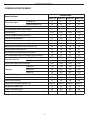
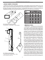
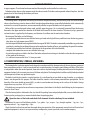
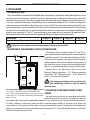
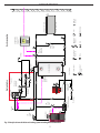
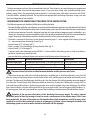
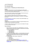
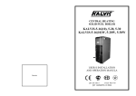
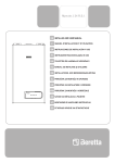
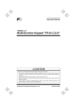
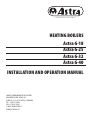
ASTRA MACHINERY PLANT AB • ANNO 1929
HEATING BOILERS
Astra G-18
Astra G-25
Astra G-32
Astra G-40
INSTALLATION AND OPERATION MANUAL
CONTACT INFORMATION OF THE FACTORY:
MACHINERY PLANT “ASTRA” AB
ULONŲ G. 33, LT-62161 ALYTUS, LITHUANIA
TEL.: +370 315 75449
FAX: +370 315 52265
E-MAIL: [email protected]
WWW.ASTRA-GAS.LT
Table of contents
1. SAFETY REQUIREMENTS................................................................................... 3
2. TECHNICAL DESCRIPTION................................................................................. 4
• General View of the Boiler.................................................................................................................... 4
• Technical Data of the Boiler.................................................................................................................. 5
• Ceramic Elements of the Boiler............................................................................................................. 6
• Turbulence Plates................................................................................................................................. 6
3. INTENDED USE................................................................................................ 7
4. TRANSPORTATION, STORAGE, UNPACKING......................................................... 7
5. INSTALLATION................................................................................................ 8
• Accumulation Tank............................................................................................................................... 8
• Description of the Emergency Cooling System Diagram........................................................................ 8
• Description of the House Heating System Scheme................................................................................ 8
• Requirements for Connection of the Boiler to the Heating System..................................................... 10
• Circuit Diagram of the Boiler............................................................................................................... 11
• Connection of the Circulation Pump................................................................................................... 12
• Mounting of the Draught Regulator................................................................................................... 12
• Regulation of the Primary Air Damper................................................................................................ 12
• Controlling the Temperature of Water Returning to the Boiler............................................................ 13
• Heating Output, Water Temperature and Water Flow Relationship..................................................... 13
• Installation of the Boiler Room........................................................................................................... 13
• Requirements for the Chimney........................................................................................................... 14
6. FUEL............................................................................................................15
7. OPERATION...................................................................................................16
• Front Control Panel............................................................................................................................ 16
• Rear Control Panel.............................................................................................................................. 17
• Preparation for Firing......................................................................................................................... 17
• Kindling Procedure of the Boiler......................................................................................................... 17
• Fire Bed and Tips for Effective Boiler Stoking...................................................................................... 18
• Regulation of the Boiler Temperature................................................................................................. 19
• Addition of Fuel.................................................................................................................................. 19
• Combustion Control........................................................................................................................... 19
• Cleaning the Boiler............................................................................................................................. 19
• Emergency Shut Down of the Boiler................................................................................................... 20
8. POSSIBLE FAULTS..........................................................................................20
9. WARRANTY AND ITS VALIDITY TERMS...............................................................21
10. ACCEPTANCE CERTIFICATE..............................................................................21
SELLING CARD..................................................................................................22
BOILER INSTALLATION PROTOCOL........................................................................22
WARRANTY AND POST-WARRANTY REPAIR CARD...................................................23
DECLARATION OF CONFORMITY...........................................................................24
INSTALLATION AND OPERATION MANUAL
This user manual was compiled following the requirements of EN 12171 “Heating systems in buildings. Procedure for the
preparation of documents for operation, maintenance and use. Heating systems not requiring a trained operator”.
1. SAFETY REQUIREMENTS
1.1.
1.2.
1.3.
1.4.
The room where the boiler is to be installed should be ventilated.
Free inflow of air into the room should be ensured.
The boiler flue connection with the chimney should be tight. Do not heat up the boiler with leaking flue connections!
The boiler should be installed in a closed heating system with a closed (membranous) expansion vessel, the volume of
which should be no less than 10% of the total volume of the heating system (including the boiler) (the volume of the
expansion vessel can be calculated according to the standard EN 12828 annex D).
1.5. A safety valve for no more than 2 bar response pressure should be fitted onto the boiler in the heating system for the
boilers Astra G-18, Astra G-25, Astra G-32, and a maximal response pressure of 3 bar for the boiler Astra G-40 (please see
Chapter 5, “Requirements for connection of the boiler to the heating system”).
1.6. Remove the accumulated soot and resin from the boiler flues, as instructed in this manual.
1.7. The room where the boiler is installed should have fire-extinguishing tools: fire extinguishers, sand box, shovel and
other tools.
1.8. Do not place flammable materials on or near the boiler.
1.9. Connect the boiler to the electric system only via a three-pole plug plugged into an adequate three-pole socket with
earthing. Protect connection cable from damages.
1.10.Observe operation of temperature control devices and gauge readings when operating the boiler. In case of faulty
operation of the boiler, stop operation and remove the fault.
1.11. Kindle the boiler and put the firewood into the boiler only as indicated in Chapter 7 of this manual.
1.12.Keep children away from the boiler! The boiler can be serviced only by adults.
1.13.Before kindling the boiler, check if the heating system is filled with water and deaerated.
1.14.The operating pressure in the heating system should not exceed the following:
• 2 bar – for boilers Astra G-18, Astra G-25, Astra G-32;
• 3 bar – for boiler Astra G- 40.
1.15.The electrical connections are factory tested and the following parameters were confirmed:
• integrity of the protective circuit – electrical resistance of the protective circuit does not exceed 0.1Ω;
• resistance of the electrical insulation – at least 1.0 MΩ;
• resistance of electrical insulation was checked at 50 Hz, 1 000 V voltage.
3
HEATING BOILERS: Astra G-18, Astra G-25, Astra G-32, Astra G- 40
2. TECHNICAL DESCRIPTION
• General View of the Boiler
1
A
B
6
7
3
13
d
8
2
9
4
k
d
12
14
C
h
S
11
5
H
D
10
B
10
N
D
17
19
20
21
16
15
L
22
23
24
18
25
Fig. 1 General view of the boiler
A – front view; B – rear view; C – top view; D - section. 1 pav. Bendras katilo vaizdas
1. Front control panel; 2. Rooftop cover; 3. Handle of the upper flue damper; 4. Doors of the combustion chambers; 5. Adjustable support legs;
6. Flow water pipe; 7. Rear control panel; 8. Sensor immersion pocket ½” of the safety temperature limiter 95°C valve; 9. Primary air regulation damper;
10. Ventilator; 11. Return water pipe; 12. Water drain nipple; 13. Connections of the cooling serpentine; 14. Flue pipe; 15. Flue cleaning cap; 16. Temperature
sensors of operation, pump and safety thermostats; 17. Thermometer; 18. Combustion chambers; 19. Upper combustion chamber opening to the flue;
20. Primary air inlet opening; 21. Secondary air inlet opening; 22. Ceramic burner; 23. Ceramic chopper; 24. Ceramic segment; 25. Opening to the flue
Astra G boiler model
Astra G-18
Astra G-25
Astra G-32
Astra G-40
B
646
646
646
660
L
750
965
965
975
H
1156
1156
1246
1176
h
925
925
1025
935
4
k
130
130
130
210
D
152
152
152
152
d
G1 1/2”
G1 1/2”
G1 1/2”
G1 1/2”
N
205
205
205
160
S
215
215
215
160
INSTALLATION AND OPERATION MANUAL
• Technical Data of the Boiler
Name of indicator
firewood, kW
wooden briquettes, kW
Class of boiler according to EN 303-5
Class of protection against electric impact
Efficiency rate,%
Power of emergency cooling system, kW
Water volume in the boiler, l
Setting range of the temperature regulator, °C
Maximum operating draught in the flue, mbar
Working pressure of water in the system, bar, max.
Testing pressure of the boiler, bar
Max. allowable water temperature in the boiler, °C
Max. allowable operating water temperature in the boiler, °C
voltage, V / frequency, Hz
Electric characteristics:
average power used, W
Level of electric protection of the boiler
height, mm
Dimensions:
width, mm
depth, mm
Weight of boiler, kg,
Threaded connection diameter
Volume of fuel chamber, l
Dimensions of the loading aperture, mm
Flue gas duct diameter, mm
Length of wood pieces, mm
Average temperature of the flue gases at the nominal heat output, °C
Nominal heat output
5
Indicator value
Astra G-18 Astra G-25 Astra G-32 Astra G-40
18
25
32
40
20
28
33
42
3
3
3
3
1
1
1
1
81-89
81-89
81-89
81-89
12
15
15
18
52
62
71
85
65-85
65-85
65-85
65-85
0.25
0.30
0.30
0.30
2.0
2.0
2.0
3.0
3.0
3.0
3.0
4.5
108
108
108
108
95
95
95
95
220/50
220/50
220/50
220/50
14
21
21
21
IP30
IP30
IP30
IP30
1156
1156
1246
1176
646
646
646
660
750
965
965
1176
260
310
330
380
1½”
1½”
1½”
1½”
67
105
130
140
350x285
350x285
350x285
350x285
152
152
152
152
330
500
500
550
165
188
195
205
HEATING BOILERS: Astra G-18, Astra G-25, Astra G-32, Astra G- 40
• Ceramic Elements of the Boiler
The boiler has ceramic elements of three types: ceramic burner 1, ceramic chopper 2 and two ceramic segments 3 (Fig. 2). The
chopper 2 must be moved to the back wall of the boiler chamber during operation of the boiler, segments 3 – resting upon the
front edge of the chopper. If needed, the ceramic burner 1 can be removed. For this purpose, use a screwdriver to remove the
sealing rope from between the ceramic burner and the frame of the boiler, then this ceramic insert can be removed.
1
Ceramic
element
1. Burner
G-18.00.003
K-30.00.007
ŠK-50.07.001
2. Chopper
G-32.01
G-32.02
3. Segments
G-18.00.004
G-18.00.004-01
2b
2a
3
Fig.2 Ceramic inserts and their positions
1. Ceramic burner; 2. Ceramic chopper; 3. Ceramic segments.
1
1
1
1
1
1
1
1
2
2
2
G-40
1
2
2
• Turbulence Plates
Turbulence plates – a technology invented and patented by
“Astra” engineers, used for capturing more heat from the hot
exhaust smoke. It forces the exhaust smoke to hold, become
turbulent and thus transfer more heat to the adjacent heat
exchanger. The core of the device consists of the turbulence
plates, positioned at an angle in the rectangular-shaped flue
channel of the boiler. The inspection aperture 1 is installed on
the top part of the flue channel (Fig. 3), covered with a screwon cover with a gasket. This aperture is used for cleaning the
flue channel and placing/removing the turbulence plates.
The turbulence plates 2, shown in Fig. 3, maintain their
position in the flue due to their force of gravity alone. They
are inserted into the flue channel or removed using a poker
3, which is provided with the boiler. Poker 3 (Fig. 3) is bent
at an angle of approximately 80° to the handle, so that the
hooked plate does not slide off. In order to be able to hook
the turbulence plate 2 with a poker, a hole has been made in
its upper part for hooking with a poker. The plate rests upon
the heat exchanger 4 of the boiler flue on four supports: two
bottom and two upper supports. When inserting the plate 2
with a poker 3 into the flue channel, first the lower position
is found, and after slightly loosening the poker, yet without
removing it from the hole, the plate is allowed to descent
onto the opposite side of the heat exchanger due to the force
of gravity until it touches the wall of the heat exchanger with
1
2
G-18
Boiler type
G-25
G-32
3
4
2
Fig. 3 Turbulence plate technology
1. Inspection aperture; 2. Turbulence plates; 3. Poker;
4. Heat exchanger of the boiler flue.
6
INSTALLATION AND OPERATION MANUAL
its upper supports. Then the tool can be removed and the next plate can be installed in a similar way.
Turbulence plates decrease the temperature of the exhaust smoke. The boiler can be operated without the plates, but then
greater losses of heat through the chimney will occur.
3. INTENDED USE
The heating boiler is designed for the heating of residential and public buildings, manufacturing shops and other buildings
where a closed heating system has been installed. Control and regulation devices are installed in the boiler, which automatically
maintain the set water temperature, ensure economically efficient usage of the boiler and safe operation.
Boilers of this type are designed to burn wood, partially generating gases. Gas is extricated (generated) from the burning
firewood in the upper combustion chamber of the boiler and burned in the lower chamber. The intensity of gas generation
and combustion is regulated by the frequency and duration of air inflow into the combustion chambers.
Advantages of the boiler are the following:
•gas generating combustion ensures effective burning of wood and a high efficiency coefficient since the burning process
takes place at a high temperature of 900°C;
•the heat output of the boiler can be regulated within the range of 40-100%. The boiler is automatically controlled using an electronic
regulator, by switching the ventilator inflowing into the combustion chambers off or on, or by regulating the speed of its rotation;
•the combustion period of one fuel load is long due to the large volume of the fuel chamber;
•complete fuel combustion ensures cost-efficient fuel usage;
•the turbulence plates installed in the flue of the boiler enhance heat exchange in the boiler and reduce the temperature
of the smoke in the chimney;
•it is sufficient to remove the ashes 1-2 times per week.
4. TRANSPORTATION, STORAGE, UNPACKING
The heating boiler is to be transported and packaged in accordance with the documentation of the manufacturer, protected
from precipitation and dust. It can be transported only in vertical position, fastened to avoid sliding and falling. If the boiler
is transported in other than vertical position, decorative surfaces may be damaged, cladding battered, control and regulation
equipment broken, built-in ceramic inserts may fall down and splinter. The heating boiler should be carefully loaded, unloaded
and transported, without any significant impact.
The boiler should also be stored in a vertical position. It is not allowed to put one boiler on top of another, as a packaging
frame is not designed for this purpose. The boiler should be stored in a closed room protected from precipitation. The air
humidity of the room should not exceed 80%, in order to avoid condensate forming on the surfaces of the boiler. Storage
temperature may vary from -40°C to +60°C.
If the boiler was transported or stored in minus temperatures, then before it is kindled, it should be kept in plus temperature
for no less than 2 hours.
After the heating boiler is delivered to the site, take off the packing frame and polyethylene film, unscrew boiler bolts and,
fastening to the packaging base, remove the boiler from the packaging base.
Open the doors of the boiler and check if all elements listed in a delivery kit are included.
The delivery kit consists of the following: boiler - 1 pc.; poker - 1 pc.; scraper - 1 pc.; draught regulator - 1 pc.; tee - 1 pc.;
operation manual - 1 pc.; support legs - 4 pcs.
Check if painted surfaces have not been damaged during transportation, if the components are not bent and if control and
regulation equipment is intact. In case you notice any inadequacies, present your claims to the vendor company.
7
HEATING BOILERS: Astra G-18, Astra G-25, Astra G-32, Astra G- 40
5. INSTALLATION
• Accumulation Tank
These solid fuel boilers are intended to be fully loaded during the operation; the most efficient mode of their exploitation is at the
nominal or maximum heat output. It is advisable to install an accumulation tank of sufficient size in their proximity, which could
accumulate the excessive heat. If the boiler is operated without the accumulation tank, its lifetime can be shortened because, in
such a case, a relatively low temperature of the outflowing water is maintained in the boiler (65-70°C). Therefore, the temperature
of the water returning to the boiler from the heating system is as low as 55-60°C. More water vapour condenses in the boiler at such
operating temperatures, more tar accumulates on the internal walls of the boiler and metal corrosion intensifies. When operating
the boiler with an accumulation tank, it is possible and advisable to maintain constantly maximum temperature of outflowing and
returning water, respectively 85°C and 72°C, then condensation of water vapour and metal corrosion will be significantly lower.
Recommended capacity of the accumulation tank is approximately 50 litres per 1 kW of nominal power of boiler:
Boiler model
Required volume of the accumulation tank, litres
Astra G-18
900
Astra G-25
1200
Astra G-32
1500
Astra G-40
2000
The boiler is to be operated only with an emergency cooling system installed!
• Description of the Emergency Cooling System Diagram
2
5
1
3
4
A thermostatic safety temperature limiter 95°C valve (Fig. 4)
protects the boiler form the overheating. If the water temperature
in the boiler exceeds 95°C, the valve automatically opens the flow
of cold water from the public water supply network through the
1. serpentine,
Į kanalizaciją;
cooling
where it absorbs the excessive heat energy and
2. Terminis
vožtuvas;
flows out
into theapsauginis
sewage. The
sensor of the valve with the external
Filtras;
thread3.½”
is screwed onto the socket on the rear wall of the boiler.
4.
Vanduo
Technical dataiš vandentiekio.
of the thermostatic safety valve are the
Slėgis 2-6 bar. Temperatūra °C;
following: Opening temperature - 95°C; Maximum operating
5. Terminio apsauginio vožtuvo sensorius.
temperature- 110°C; Operating pressure - 10 bar; Bulb of the
sensor - L=142 mm, external thread ½“.
The emergency cooling system protecting the
boiler from overheating cannot be used for heating
domestic water.
Fig. 4 Connection diagram of the emergency cooling system
• Description of the House Heating System
1. To sewage; 2. Thermostatic safety temperature limiter 95°C
Avarinio
aušinimo
pajungimo
schema
Scheme
valve; 3. Filter;44.pav.
Water
from public
watersistemos
supply, pressure
2-6 bar,
temperature 12°C; 5. Sensor of the thermostatic safety temperature The house heating system with an accumulation tank could be
limiter 95°C valve.
divided functionally into two circles: heat production and heat
consumption. Both circles operate independently and interact in the accumulation tank. The heat production circle consists
of a boiler, Laddomat 21 thermostatic mixing unit with a circulation pump installed in it, expansion vessel, fittings and
accumulation tank. The intended use of this circle is to charge the accumulation tank only. To charge the tank, the boiler could
operate on its maximum heat output and outflowing water temperature 85°C. That mode of boiler operation is optimal for
the boiler and combustion process itself.
8
9
Fig. 5 Principle scheme of the house heating system including heat accumulation
Min 65oC!
T
Pump
Control
Heating Boiler
TM
Flow
Control
Valve
Flow
Control
Valve
Water Supply
T
Automatic Water
Addition Valve
Pump Control
Thermostatic
Switch
T
Accumulation Tank
Air Outlet
T
Pressure Relief
Valve
Thermometer
Other Notations:
From Water Supply
TM
Domestic Water
Preparation
Thermostatic
Mixing Valve
Membrane
Expansion Vessel
Domestic Water
Recirculation
Water Heating
Laddomat 21
Thermostatic Mixing Valve
Air Outlet
Heat production
TM
Pump
TM
Return
Overflow
Valve
3-Way
Servo Drive
Mixing Valve
Thermometer Manometer
M
Hot Water
Valve
Manometer
With Valve
T
Programmable
Heating System
Processor
Heat consumption
Return Valve
Filter
Automatic
Air Outlet
Heating System Return
Heating System Supply
INSTALLATION AND OPERATION MANUAL
HEATING BOILERS: Astra G-18, Astra G-25, Astra G-32, Astra G- 40
The heat consumption circle uses the heat accumulated in the tank. The circle consists of a room thermostat or a programmed
control processor, room or/and outside temperature sensors, 3-way servo drive, mixing valve, underfloor heating system,
radiators, piping, fittings. The programmed processor controls a 3-way mixing valve, which allows more or less heat (45-60°
C) into the radiators, according to demand. This way of heat consumption allows the heating of the house as long as the tank
stores heat independently from the boiler.
• Requirements for Connection of the Boiler to the Heating System
The following requirements should be fulfilled when installing the boiler:
• The boiler should be installed in a closed heating system with a closed membranous expansion vessel, the volume of which should
be no less than 10% of the total volume of the system. A closed heating system is a kind of system with no free access to atmospheric
air, which actuates corrosion. Due to this, drainage of water from the system without an important reason is undesirable, e. g. in
summer. It is also necessary to ensure watertightness of the system in order to need fewer refills with fresh water containing free
oxygen. The quantity of the additional water let in should not exceed 5% of the system water volume per year;
• The boiler is connected to the heating system through connection pipes 6 – water supplied to the heating system and
11 – water returning from the heating system (Fig. 1);
• Internal threads G 1½” of pipes 6 and 11 ;
• There is a nipple 12 for water filling or draining from the boiler (Fig. 1);
• Internal thread G ½” of the nipple 12;
• A pressure relief valve conforming to norm EN1268-1 is to be installed in the heating system as close to the boiler as
possible at a location easy to reach by hand;
• pressure relief valves and control devices must conform to the following technical characteristics:
Instrument
Pressure relief valve
Pressure relief valve
Thermometer-manometer
Technical characteristics
Connection diam. does not exceed ½”, set opening pressure 2 bar
Connection diam. does not exceed ¾”, set opening pressure 3 bar
Range of temperature 0-120°C, pressure 0 – 4.0 bar
Type of boiler
Astra G-18, Astra G-25 , Astra G-32
Astra G-40
All boilers
There must be no ball valves installed between the boiler and the pressure relief valve.
• Water from the pressure relief valve should be conducted via an offtake pipe. It should be conducted in a way that will
allow the water passing through the pressure relief valve to flow safely, avoiding exposure of people and electrical parts of
the boiler. The diameter of the offtake pipe should be no less than the diameter of the offtake opening connection nipple of
the safety valve. The total length of the offtake pipe should not exceed 2 m. No more than 2 elbow joints at angles of 90° are
to be used when installing this duct. No ball, mixing or other valves are to be installed in the water offtake pipe. This offtake
pipe is to be installed in a way that will make the flow of the passing water visible. If part of the pipe installed is hidden, e. g.,
in a sewerage pipe, then such a pipe should have a special funnel enabling visual observation of the offtake flow of water.
Operation of the pressure relief valve is to be checked at least once a month. The valve is opened
for a short period of time, by turning its head, to reveal a small amount of the offtake water. If this is not
done periodically, the parts of the valve can stick together due to high temperature and fail to open, when
required. In case the safety valve fails to open in an emergency situation, serious damage to the boiler and
the heating system can occur as well as hazard to the health and life of people.
10
INSTALLATION AND OPERATION MANUAL
In order to guarantee natural water circulation of water in the boiler, the pipework between the boiler
and the mixing valve in the line boiler–mixing valve–boiler is to be of the same diameter and correspond to
the diameter of the connection pipes of the boiler.
• Circuit Diagram of the Boiler
220 V
P
1
N
S1 - įva
S2 - ve
jun
SK- ava
SK2- si
SK3- d
F - sau
M - ve
- šil
cirk
U - te
jut
M
P
L
2
3
N
L
4
5
6
N
P
L
7
8
N
L
9
10
11
12
N1
L15
N1
L12
L1
SK3
L11
SK2
F
L12
L12
L13
L11
L13
L11
S2
L14
L14
N1
N
L1
L
L15
S1
SK
U
U
U
Fig. 6 Circuit diagram of the boiler
S1 - power supply switch; S2 – ventilator switch; SK – emergency ventilator shutdown 95°C thermostat; SK2- circulation pump thermostat;
SK3- operation thermostat; F - fuse; M - ventilator;
- circulationkatilo
pumpelektros
of the heating
6 pav. Montažinė
schemasystem; U - water temperature sensors.
• An electric installation with earthing, in accordance with the electric safety regulations in force, is to be installed when
connecting the electric part of the boiler.
Protect the isolation of the mains cable against damage.
11
HEATING BOILERS: Astra G-18, Astra G-25, Astra G-32, Astra G- 40
• Connection of the
Circulation Pump
1
3
2
In order to insure a continuous flow of
1
water, a circulation pump is to be installed
in the system, on the return water pipe
behind the mixing valve. The electronic
controller of the boiler controls the
pump. Before connecting the circulation
pump, remove the rooftop cover of the
boiler (Fig. 7). The cover is removed in
the following sequence: 1) unscrew two
fastening bolts, 2) lift the backside part
of the cover, 3) push the cover forward
and then lift it up. Connect the wire of
the circulation pump to the 12-way
electric terminal connector, contacts No Fig. 7 Removing the rooftop cover of the boiler
11 and 12, marked with the sign (See 1. Unscrew bolts; 2. Lift the backside of the cover; 3. Push the cover forward , then raise.
Fig. 6 “Circuit diagram of the boiler”). Connect the earthing wire of the pump to the contact No. 1 on the same connector.
• Mounting of the Draught Regulator
At first, mount the tee 1 (Fig. 8) present in the supply set, on the boiler flow pipe 6 (Fig.
1). Then, install the draught regulator 2 (Fig. 8) into the lateral pipe of the tee. Connect
the lever of the draught regulator with the ventilator lid. When the temperature of the
water in the boiler rises, the lever descends, and the main air supply damper 4 cloaks
the opening of the air duct, thus restricting the air supply to the combustion chambers.
Damper 4 (Fig. 8) should not completely close the air supply opening
in any mode of the boiler operation. It is recommended to sustain at least a
3-8 mm gap to the opening in the lowest position of the damper.
The position of the damper 4 is set by changing the length of the connecting chain of
the draught regulator. First, decide at what temperature to keep the flow water during
the boiler’s use. 75° C or even higher is recommended. By reaching this water temperature,
the boiler should considerably lower the air supply to the combustion chambers and the
burning process must slow down as a consequence. At this moment, the damper 4 must
go down to its lowest position. Fire up the boiler and observe the indications on the boiler
thermometer. When the targeted water temperature (75° C) is reached, fix the damper 4 to
the lowest position by fastening the lever of the draught regulator and choosing the length
of the connecting chain. Remember: a 3-8 mm gap should be left between the damper
and the air supply opening. The exact size of the gap depends upon the draught of your
chimney. The worse the draught, the greater the gap should be.
1
2
3
4
5
Fig. 8 Mounting of the draught
regulator
1. Tee; 2. Draught regulator; 3. Primary
air damper; 4. Main air supply damper;
5. Ventilator.
• Regulation of the Primary Air Damper
The primary air damper 3 (Fig. 8) is set up in the factory. To inspect the positioning of the damper: loosen the fixing screw
and push the shaft of the damper forward until it gets stuck. Then pull the shaft 5 mm backwards and fix it with the screw.
12
1. Trau
2. Triš
3. Pirm
skle
4. Pag
skle
5. Ven
INSTALLATION AND OPERATION MANUAL
• Controlling the Temperature of Water Returning to the Boiler
It is absolutely necessary to maintain the temperature of the water returning from the heating system to the boiler at a
constant level, no less than 65°C, as this will prolong the lifetime of the boiler and will make the combustion process more
effective. This is because when a constant high temperature of water returning to the boiler is maintained, there arises
significantly less water vapour condensation inside the boiler. The heavy water condensation is harmful to the boiler, because
deposits of tar, pitch and soot accumulate on the walls of the heat exchanger, causing intense metal corrosion. Moreover, the
resulting layer of soot impedes effective heat transfer and the efficiency of the boiler falls.
In order to maintain the temperature, we recommend installing the small circulation circle together with a Swedish-made
thermoregulation device, “Laddomat 21-60”. Make sure that the “Laddomat” is supplied with the 78°C or 72°C thermostat
cartridge. The mentioned temperature is the one at which the valve of the device opens completely. However, the actual
temperature of the water returning from the system and getting into the boiler after mixing, is 5-6°C lower. The higher the
temperature of the return water is, the better it is for the boiler. Thermoregulation devices of other manufacturers could be
used for maintaining the temperature of the returning water as well.
• Heating Output, Water Temperature and Water Flow Relationship
The heating output supplied to a heating
Difference
Heating output, kW
of water
system depends directly upon the difference of temperatures
18
25
32
40
Water flow, l/min
Δt, °C
flow and return water temperatures Δt and the
11
24
33
43
53
intensity of the water flow circulating through
12
22
31
39
49
the boiler. The boiler will fail to reach the desired
13
20
28
36
45
temperature of the flow water if the returning
14
19
26
33
42
water temperature is too cold or the circulation
15
18
24
31
39
16
16
23
29
37
pump is too powerful. This will happen because
17
16
22
28
34
the boiler will be forced to produce a larger
18
15
20
26
33
heating output than it has been designed for.
The most effective boiler operation occurs when the difference between the flow and return water temperatures is 12-14°C.
If the boiler is forced to operate with a 20°C or even greater temperature difference, it will work ineffectively, consume too
much of fuel, and the combustion period of one fuel load will consequently shorten. If the previously mentioned difference of
temperatures is kept less than 10°C, the fuel in the boiler will again burn inefficiently and fume because of a lack of air supply.
If you know the water flow intensity near your boiler, in the above presented table you can check, what the difference of flow
and return temperatures your boiler is capable to maintain, when operating at the nominal heating output.
Do not forget to keep the returning water temperature as high as possible, at least 65°C or even higher!
It is necessary to assure that a thermometer is installed on the returning water pipe, in order to be able to
observe this temperature at any time!
• Installation of the Boiler Room
The boiler room should be ventilated. The required air inflow necessary for combustion should be also ensured. For this
purpose, boiler room doors should have ventilation grating or there should be a sufficient gap between the doors and the
floor. If there is no possibility to supply air in from another rooms or the house is very tight, it will be necessary to install an
opening in the exterior wall. The cross-section area of the opening should be at least 0.001 m2/kW.
Place the boiler as close to the flue as possible on a hard concrete levelled basement. Leave at least 600 mm gap between the
backside casing of the boiler and the room wall for boiler servicing and cleaning. The smallest distance between a lateral casing
13
HEATING BOILERS: Astra G-18, Astra G-25, Astra G-32, Astra G- 40
of the boiler and a building structure is 400 mm. If the building structure is made of flammable materials, this distance should be
doubled. A freely approachable space of at least 800 mm should be then left from the opposite side of the boiler to ensure access
to the backside of the boiler, for its servicing and cleaning. The floor under the boiler, within the distance of 50 cm in front of it and
within the distance of 30 cm around the boiler should be made of inflammable materials. Screw supporting legs onto the base of
the boiler and level the boiler with screw nuts using a level; then connect the heating system circulation pump to the boiler.
The smoke exhaust pipe of the boiler should be connected to the chimney through a metal duct. The internal diameter of
the metal connecting duct should be at least the same as the external diameter of the smoke exhaust pipe of the boiler. To
improve the draught, the connecting duct between the boiler and the chimney should be installed at an inclination towards
the boiler. All junctions should be carefully tightened using a heat-resistant material and insulated using thermal insulation.
If an additional damper is installed between the boiler and the chimney for the draught control purpose,
the damper should not close more than 2/3 of the cross-section area of the opening in its fully closed position.
• Requirements for the Chimney
It is recommended to insert acid-resistant stainless steel liner, if the chimney is made from masonry. It improves draught of
the chimney and protects the masonry from destruction due to the impact of condensate. Internal diameter of the liner should
be no less than the external diameter of the smoke exhaust pipe of the boiler. The chimney liner can be round or oval. It is not
recommended to use rectangular-shaped liner as, due to the temperature fluctuations, its walls deform, gaps appear at the
element junction points, through which the condensate falls on the walls of the bricks chimney. Additional air is sucked in, which
reduces draught of the chimney. Draught for each boiler model should correspond to the referred value of draught in the table
“Technical data”. The liner should be factory made. Minimum permissible height of the chimney should be at least 6m. The top
of the chimney should be above the ridge at least by 0.5m. If the chimney is further from the ridge than 1m, the angle horizon-
Fig. 9 Positioning of a chimney in respect to vicinity objects
14 esanþiǐ objektǐ atžvilgiu
8 pav. Kamino padơtis greta
INSTALLATION AND OPERATION MANUAL
the ridge- the cap of the chimney should consist 10° or less degrees. Draught of the chimney can also be negatively affected by
various obstructions near the building: trees, hills, other buildings. Fig. 9 presents the recommended minimal angles between the
chimney, nearby objects and the horizon. Angles larger than those indicated will cause reduction of draught of the chimney.
The connection of other devices to the chimney to which the boiler is connected is prohibited.
The chimney should be cleaned at least once a year!
6. FUEL
The boiler is fired only by wood logs and wood briquettes. It is possible to fire it with fuel peat briquettes, however the
operation of the boiler becomes less comfortable for the user as it is necessary to remove the ashes of these highly ashproducing briquettes after each loading. The ceramic elements of the lower chamber can be damaged if they are removed
every day when cleaning, thus their lifetime will be shorter. Therefore, we recommend usage of fuel peat briquettes only in
rare, exceptional cases.
It is recommended to fire dry firewood with a moisture content of 12-20 %. The drier the firewood, the larger its calorific capacity.
When the moisture content of the firewood is 20%, the heat potential of 1 kg is approximately 4 kWh; when the moisture
content is 50%, its heat potential is reduced by half.
The length of the firewood should be at least 5cm shorter than the length of the boiler combustion chamber.
Type of boiler
Astra G-18
Astra G-25
Astra G-32
Astra G-40
Length of firewood, mm 310
500
500
550
The recommended thickness of the wood logs is 100-150mm. Thicker pieces of firewood should be split at least once. Up to
15% of the fuel load can consist of fine wooden splinters and sawdust. However, they must be loaded in such a way so as not
to block the opening of the ceramic burner 22 (Fig. 1) connecting the upper and lower chambers of the boiler.
Do not fire freshly prepared and excessively damp pieces of firewood. The operation of the boiler
becomes inefficient, deposits of resin emerge on its inside walls as well as excessive condensate. Corrosion of
the boiler takes place several times faster when firing it with freshly prepared wood or wood that has been
dried outside for several months only!
Recommendations for firewood preparation:
• put split wood in a properly-ventilated place – if possible, in a sunlit place;
• firewood should be well sheltered from rain and snow;
• pieces of split wood should be stacked with sufficient gaps between them so that the freely-circulating air can blow away
the moisture evaporated from the pieces of firewood;
• there should be sufficient space above the heap of firewood below the roof and sufficient ventilation to remove the moist air;
• it is not advisable to store freshly-cut firewood in a basement since the firewood needs sun and free air movement to dry.
Dry wood can be stored in the basement where sufficient ventilation is guaranteed;
• it is recommended to dry the split firewood outdoors under the above-mentioned conditions. Depending on the type of wood,
soft wood (alder, asp, fir, poplar) must be dried for at least 8 months, and hard wood (oak, ash, birch) for at least 20 months.
Firing the boiler with coal, rubber or plastics is prohibited. However, loading wood briquettes into the
boiler together with their plastic packaging bags is allowed.
15
HEATING BOILERS: Astra G-18, Astra G-25, Astra G-32, Astra G- 40
7. OPERATION
• Front Control Panel
1
2
3
4
Fig. 10 Front control panel
1. Operation thermostat knob; 2. Thermometer; 3. Green button for switching the voltage of the boiler on and off; 4. Red button for switching on the ventilator.
The front control panel contains the operation thermostat 1 (Fig. 10), the thermometer 2, the green button 3 of the main
supply and the red button 4 for switching on the ventilator. The buttons light up in the ON position.
The function of the operation thermostat 1 is to switch off the boiler ventilator when the targeted water temperature
is reached. Then, the combustion in the boiler slows down and the water temperature in the boiler does not rise further.
The position of the operation thermostat 1 knob should be set so that its targeted temperature would be several degrees
less than targeted temperature of the draught regulator (see the chapter “Mounting of the draught regulator”). Then the
operation thermostat 1 will switch off the ventilator a little bit earlier than the draught regulator would descend the damper
4 (Fig. 8) into its lowest position. The appropriate position of the operation thermostat knob should be found and marked
with a pencil, or a scratch should be made on the case of the knob. This position should be defined in the next way: first, turn
the thermostat knob to maximum. Then, set the draught regulator 2 (Fig. 8) to the targeted temperature, for example to 75°
C. Start the boiler and allow it to reach a 75° C temperature. Then, turn the thermostat knob in the direction of the lower
temperature until you hear a “click”sound. Turn the knob a little bit further and mark this position on the knob case with a
pencil. Now you have found the appropriate setting position of the operation thermostat 1 (Fig. 10).
The green ventilator button 4 (Fig. 10) has three positions. The position 0-60° C is used to turn on the ventilator during the
ignition of the boiler. At this state, the ventilator will be operating permanently. The central position , “OFF,“ is intended to
switch off the ventilator, the button lamp then does not light. After the initial phase of kindling the boiler, when the water
temperature in the boiler overlaps 60° C, the ventilator is usually turned to the position 60-90° C. This setting switches off the
ventilator automatically after the combustion in the boiler has ended and the water temperature has dropped below 60° C.
If you forget to switch the ventilator to the 60-90° C position, nothing serious will happen, just the ventilator will be rotating
permanently even after the combustion in the boiler will come to the end.
The ventilator will be switched off equally in both the 0-60° C and the 60-90° C positions when the safety
temperature limiter 95° C thermostat 2 (Fig. 11) trips, the operation thermostat 1 (Fig. 10) switches it off.
The circulation pump control thermostat SK2 (Fig. 6) is also located inside the front control panel and is not observable
from the outside. It has two functions: 1. Turn on the circulation pump when the water temperature in the boiler reaches
60° C, 2. Turn on the ventilator if the button 4 (Fig. 10) is in the 60-90° C position and the water temperature in the boiler is
higher than 60° C. Consequently, this thermostat will switch off both the ventilator and the circulation pump, when the water
temperature in the boiler drops below 60° C. To learn more about the control devices of the front control panel, please, refer
to the chapter “Kindling procedure of the boiler”.
16
INSTALLATION AND OPERATION MANUAL
• Rear Control Panel
The following safety devices are installed in the rear control panel: thermal fuse 1 and
1
electric fuse 2 (Fig. 10). The purpose of the thermal fuse, otherwise called the maximum
boiler temperature emergency thermostat, is to switch off the boiler ventilator if water
temperature in the boiler exceeds the maximum permissible 95°C due to unforeseen
reasons. The temperature sensor of the thermostat is installed in a dedicated sleeve
16 (Fig. 1). The burning intensity decreases when the ventilator is switched off and the
water temperature decreases. When the emergency thermostat trips, the lamp of the
ventilator switch 3 on the front panel switches off (Fig. 9) and the lighting indicator bulb
4 “Firing off” on the electronic regulator lights up (Fig. 11). In this case, it is necessary Fig. 11 Rear control panel
to find out the causes of tripping and to remove them. After the boiler cools down, the 1. Thermal fuse ; 2. Electric fuse.
emergency thermostat can be returned to its normal operating mode. For this purpose,
unscrew its cover and depress the red button.
2
The cause of overheating of the boiler and tripping of the emergency thermostat must be found and
removed. If this is not done, the risk of serious damage to boiler equipment as well as hazard to human health
and life remains. If the user cannot locate and remove the cause of tripping of the emergency thermostat, a
professional servicing company must be consulted!
The electric fuse is designated to protect the elements of the electric circuit in case the current in the mains exceeds 2 A. If the
fuse is damaged, the boiler will not switch on and its indicator lamps will not light. In this case, remove and replace the fuse.
The rear control panel of the boiler is grounded.
• Preparation for Firing
Before kindling the boiler, check the position of the ceramic chopper 2 in the lower combustion chamber: the edge of the
chopper must be in contact with the rear wall of the boiler (Fig. 2). Place two ceramic segments 3 (Fig. 2) on the chopper so
that they contact the walls of the boiler chamber.
Fill the heating system with water. The filling pressure should be 0.2 bar bigger than the hydrostatic pressure, yet it must
not exceed the operating pressure of the boiler. After filling the system with water, perform a visual check of the tightness of
the entire system. Perform it before kindling the boiler, then again after kindling and reaching the nominal operating mode.
Check if the heating system is properly deaerated.
• Kindling Procedure of the Boiler
Before kindling the boiler, check whether all requirements indicated in the section 1 are executed.
Open the damper of the upper flue 19 by pulling the handle 3 (Fig. 1) towards yourself. Open the door of the upper
combustion chamber, put dry smaller kindling wood pieces and paper on the ceramic bottom so that the paper protrudes into
the lower combustion chamber through the rectangular opening of the ceramic burner 1 (Fig. 2) – this way, it will be easy
to kindle the boiler through the lower combustion chamber. Put some of the easily flammable materials and larger pieces of
kindling wood and firewood atop. Load the wood without any large gaps at the top of combustion chamber. Bigger pieces of
firewood should be loaded in the middle and smaller prices at the sides, because the walls of the combustion chamber slow
down the combustion of the bigger pieces of wood, due to their lower temperature.
Do not cover the entire opening of the upper flue 19 (Fig. 1) with the wood, because it will make kindling
more difficult.
17
HEATING BOILERS: Astra G-18, Astra G-25, Astra G-32, Astra G- 40
The first time, kindle the boiler using only paper and small pieces of wood in order to safely remove the
moisture remaining in the ceramic elements.
Switch on the voltage, using button 3 (Fig. 10) on the front control panel. Set the required outflowing boiler water
temperature using the operation thermostat knob and draught regulator (see more in the chapter “Front control panel”); we
recommend a temperature of at least 75°C or – even better – a higher temperature. Close the door of the upper combustion
chamber, open the lower door and set the kindling material on fire. Observe the rising water temperature in the thermometer
2 (Fig. 10) display. Keep the lower door open until the boiler water will heat up to 40°C. Then, close the lower door, close the
damper 19 of the upper flue by pushing its handle 3 (Fig. 1). Then, switch on the ventilator switch 4 on the control panel
(Fig. 10) into the position 0-60° C. The ventilator will start rotating and the water temperature will rise further. After the
temperature passes 60° C, turn the ventilator switch to the 60-90° C position. The boiler then will operate in automatic mode:
it will try to reach and maintain the setpoint temperature of the water outflowing from the boiler.
When firing the boiler for the first time, the condensation of the residual moisture and drainage of water in the lower
combustion chamber occurs. This is not a shortcoming. After kindling the boiler several times, this phenomenon disappears.
The doors of the boiler combustion chambers should be tightly closed, there should be no flue gases
seeping into the ambience through them. Door tightness is regulated by screwing or unscrewing the hinge
and lock screws of the door.
• Fire Bed and Tips for Effective Boiler Stoking
The hot embers and charcoal in the boiler are called the fire bed. Combustible gases emerge from there and are further
burned in the lower chamber of the boiler. The optimal fire bed height during boiler operation is approximately 4-5 cm above
the bottom of the fuel chamber. The output of the boiler ventilator is deliberately chosen with the purpose of sufficiently
supplying the fire bed with air. Then, the most effective combustion of wood gases takes place. Avoid a situation when the
volume of the fire bed expands several times. This situation can occur if very dry and thinly cut wood gets loaded into the
fuel chamber. Consequently, the volume of the fire bed increases rapidly during the burning process and soon a lack of air
occurs, allowing the combustible gases to escape unburned through the chimney into the atmosphere. An indicator of this
undesirable course is dense fumes emerging from the chimney.
The best way to stoke a boiler is the so-called two stages method. During the first stage, the boiler is stoked with a small
amount of fuel. The aim of this phase is to warm up the boiler and form the optimal fire bed. The second stage is intended for
full fuel loading and to perform the main combustion.
The first stage: Prepare thin-cut wood and paper for an easy start. The volume of loaded fuel should be about 15-20 % of the
fuel chamber’s capacity. Open the upper flue damper 3 (Fig.1) and both boiler doors, put the wood and paper inside. Kindle
the paper, make sure that the firing starts and close the upper door. After the temperature of water in the boiler reaches 45°
C, close the damper and the lower door and turn on the ventilator. Let the boiler burn further for 30 minutes.
The second stage: Load the boiler fully. If wood briquettes are used for stoking, load approx. 70 % of the fuel chamber’s
capacity. Before opening the door, turn off the ventilator. Open the damper 3 (Fig. 1) by pulling the handle towards yourself,
and after some time, open the upper boiler door very slowly to avoid smoke escaping into the room. Load the fuel, close the
door and push the handle of the damper 3 (Fig. 1). Press the ventilator knob 4 (Fig. 10) on the front control panel into the
„60-95° C“ position. The ventilator will start and the boiler will continue its firing mode.
If you lack time to stoke the boiler in the two stages mode as described above, then stoke it by one stage. The boiler will operate
as usual. But if there is the possibility to do so, use the two stages mode in order to achieve an even more effective combustion.
18
INSTALLATION AND OPERATION MANUAL
• Regulation of the Boiler Temperature
See the chapters “Mounting of the draught regulator”and “Front control panel”.
• Addition of Fuel
While adding firewood into the combustion chamber, during boiler operation or after a load has burned off, keep strictly
to the following procedure:
1. Open the damper of the upper flue 19 by pulling the handle 3 towards yourself (Fig. 1).
2. Switch off the ventilator switch 3 (Fig. 9).
3. Wait at least 20 seconds, allowing the smoke to be removed by draught; then slowly open the upper door.
4. Put the firewood in and close the door tightly.
5. Switch on the ventilator to the 0-60° C position, if the actual water temperature is lower than 60° C.
6. Close the damper of the upper flue 19 by pushing handle 3.
7. Switch the ventilator button to the 60-90° C position, after the actual water temperature has rised over 60° C.
If operated following this order, smoke and carbon monoxide will not enter the room. Water temperature and pressure in
the system are checked by readings of the thermometer-manometer, installed in the heating system.
• Combustion Control
The status of the boiler firing process can be seen from the indications of the thermometer 2 (Fig. 10). The firing is active if
the temperature of water in the boiler exceeds approximately 60° C. The flame in the boiler can be checked by opening the
door of the lower combustion chamber when the ventilator is on. The visible tongue of flame has to be yellow or yellow-red
and reach the ceramic element; this means the firing is proceeding in an optimal manner.
Do not keep the lower door of the boiler open for extended periods of time during firing: the lower chamber
contains gases which, when escaping into the boiler room in larger amounts, can impair human health.
• Cleaning the Boiler
Ashes are removed from the boiler every 4-7 days. Open the door of the upper combustion chamber and shovel ashes down to the
lower chamber. Open the door of the lower chamber, take out only ceramic segments 3 (Fig. 2), pour ashes to a metal box. It is not
necessary to take out the triangle ceramic chopper 2 (Fig. 2) at the time of cleaning, ashes underneath it may be raked using scraper.
In any case, strictly follow the established procedure when opening the upper door: open the damper
of the upper flue, then after 20 seconds, open the boiler door.
Clean boiler chambers from tar, pitch and scurf once or twice a month. Clean the boiler when the fuel has been completely
burned and the boiler is cooled down to at least +40°C.
Open the upper cap 15 for cleaning the flue (Fig. 1). Remove the turbulence plates from the flue by hooking them and
pulling them out with the poker, then clean them using a scraper. Clean tar and scurf from combustion chambers and flue
walls using a scraper and metal hog. Clean with the doors of the combustion chambers open. The soot residues falling down
from the flue walls during the cleaning process are raked out of the boiler through the lower opening of the combustion
chamber 25 (Fig. 1), pulling them outwards. When finished, place the turbulence plates back and close the cleaning cap.
Control water pressure in the heating system at least once every two weeks. If the pressure drops,
raise it by filling up the system with more water. If the boiler is not being heated for a longer time, drain the
water out of the system when air temperature is below 0°C!
19
HEATING BOILERS: Astra G-18, Astra G-25, Astra G-32, Astra G- 40
• Emergency Shut Down of the Boiler
If for some reason you must immediately shut down the operating boiler, by any means do not pour water on the kindling
wood! The boiler can burst!
It is very convenient to use dry sand for emergency extinction. There should be ~50kg of dry sand in the boiler room. Sand
not only isolates burning firewood well from the air oxygen but also cools down the burning zone. Then, when the boiler
cools down, sand can be easily cleaned and removed.
8. POSSIBLE FAULTS
Fault
1. The set
temperature
cannot be
reached
Cause
Not enough water in the heating system
Too low temperature of the return water
Thermoregulator or ventilator is defective
Poor quality fuel: high moisture content,
too large pieces of firewood
Heating surfaces of the boiler are very dirty
No draught in the chimney due to accumulated
impurities
The ceramic burner is congested
Ventilator damper is stuck
2. Smoke escapes The door-sealing rope is damaged
through the
Door is not tight along the entire perimeter
boiler door
Problem solution
Fill up
Raise the return water temperature
Repair or replace
Use dry fuel, split firewood
Clean
Clean
Clean
Move or clean
Replace with a new one
Adjust hinge supports and door lock (regulated
screwing or unscrewing of door hinge or lock
screws) (see Fig. 13)
Fig. 13 Adjustment of the door and lock mechanism
3. Ventilator is
not operating
No draught in the chimney due to accumulated
impurities
Emergency thermostat has tripped, light of the
ventilator switch is off
Power supply failure
20
13 pav. Durelių ir užrakto mechanizmo reguliavimas
Clean
Unsrew the thermostat 1 (Fig. 10) cover and
press the button under it. It is absolutely
required to define and remove the causes of
tripping of this thermostat in order to avoid
hazards to property and human health!
Check electric fuses of the electric panel of the
building; call electrician
INSTALLATION AND OPERATION MANUAL
9. WARRANTY AND ITS VALIDITY TERMS
The manufacturer provides a warranty for the boilers, the main conditions of which are the following:
•the connection of the boiler to the heating system as well as the initial kindling, adjustment and repairs are carried out by
an authorised company;
•the boiler is connected to the heating system and operated following the requirements of this operation manual;
•the duration of the warranty period for the boiler is the following:
- for the heat exchanger of the boiler against leaking – 60 months,
- for other parts of the boiler – 24 months.
•the warranty repairs are performed when the fault has occurred due to the manufacturer’s fault;
•the warranty term is not extended after removing the faults which have occurred during the warranty period;
•boiler cleaning and heating system adjustment works are not covered by the warranty;
•the damage caused to the premises and the property in the premises due to the boiler fault will not be compensated;
•the warranty repair works and replacement of parts during the warranty period are free;
•the warranty period starts from the boiler purchase date;
•the warranty is valid only if the boiler is installed, connected to the heating system and operated following the requirements
of this manual.
The warranty does not apply in the following cases:
•in case the heat exchanger is limed;
•in case the water or other liquid inside the boiler has been frozen;
•in case of fault of the boiler due to improper operation;
•in case of fault of the boiler due to improper connection to power supply;
•in case the boiler parts are mechanically damaged;
•in case the boiler is connected to the heating system not in accordance with the diagrams and requirements of the
operation manual.
The post-warranty repair works will be carried out at the expense of the owner of the boiler.
The buyer must follow all the requirements of this operation manual during transportation, storage
and operation, otherwise the manufacturer warranty does not apply.
10. ACCEPTANCE CERTIFICATE
The heating boiler Astra G- ......................., serial No. .......................................,, conforms to the technical documentation and
requirements of standard EN 303-5 and is approved as fit for operation.
Manufacturing date 201 ..................................................................................................
L. S.
Head of Quality Service ....................................................................................................
21
HEATING BOILERS: Astra G-18, Astra G-25, Astra G-32, Astra G- 40
SELLING CARD
Boiler sold by:
Company: ...............................................................................................................................................................................................
Address: ..................................................................................................................................................................................................
Telephone:..............................................................................................................................................................................................
Date of sale: ...........................................................................................................................................................................................
Signature: ...............................................................................................................................................................................................
BOILER INSTALLATION PROTOCOL
Boiler was installed by:
Company (technician): ...........................................................................................................................................................................
Address: ..................................................................................................................................................................................................
Telephone:..............................................................................................................................................................................................
Installation date:....................................................................................................................................................................................
Installation data:
Height of the chimney: ..........................................................................................................................................................................
Diameter of the flue: .............................................................................................................................................................................
Draught of the chimney: .......................................................................................................................................................................
Other information concerning installation: ..........................................................................................................................................
.................................................................................................................................................................................................................
.................................................................................................................................................................................................................
The boiler was tested on site, the control and safety elements were checked and found to be operating properly.
Person responsible for installation and testing: ..................................................................................................................................
(Name, surname, signature of the employee)
I accept the installation works: .............................................................................................................................................................
(Name, surname, signature of the client)
22
INSTALLATION AND OPERATION MANUAL
WARRANTY AND POST-WARRANTY REPAIR CARD
Boiler repaired by:
Company (technician): ...........................................................................................................................................................................
Address: ..................................................................................................................................................................................................
Telephone: ..............................................................................................................................................................................................
Repair date: ............................................................................................................................................................................................
Information on fault, works performed:...............................................................................................................................................
.................................................................................................................................................................................................................
.................................................................................................................................................................................................................
Signature of the technician: ..................................................................................................................................................................
23
DECLARATION OF CONFORMITY
LT
Manufacturer: Machinery plant “Astra” AB
Address: Ulonu g. 33, 62161 Alytus, Lithuania
Product designation: heating boilers Astra G-18, Astra G-25, Astra G-32, Astra G-40
We declare that the above-mentioned products conform to the requirements of directives 97/23/EEC Article 2.3 and 2006/95
EEC.
The following standards were applied for the above-mentioned products:
LST EN 303-5
LST EN 12828
LST EN 60335-1
LST EN 60529
Procedure of conformity evaluation in accordance with Article 2.3 of 97/23/EEC was performed by “Inspecta”, www.inspecta.
com. Certification No. 2-4.2.1/619/2012
Alytus , 201 ..............................................................................
(date)
Gražvydas Eimanavičius, project manager