1
ADSP-2189M
Byte Memory
The byte memory space is a bidirectional, 8-bit-wide, external
memory space used to store programs and data. Byte memory is
accessed using the BDMA feature. The byte memory space
consists of 256 pages, each of which is 16K × 8.
The byte memory space on the ADSP-2189M supports read
and write operations as well as four different data formats. The
byte memory uses data bits 15:8 for data. The byte memory
uses data bits 23:16 and address bits 13:0 to create a 22-bit
address. This allows up to a 4 meg × 8 (32 megabit) ROM or
RAM to be used without glue logic. All byte memory accesses
are timed by the BMWAIT register and the wait-state mode bit.
Byte Memory DMA (BDMA, Full Memory Mode)
The Byte memory DMA controller allows loading and storing of
program instructions and data using the byte memory space.
The BDMA circuit is able to access the byte memory space
while the processor is operating normally and steals only one
DSP cycle per 8-, 16- or 24-bit word transferred.
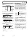
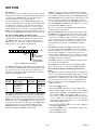
15 14 13 12 11 10
0
0
0
0
0
0
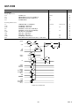
BDMA CONTROL
9 8 7 6 5
0
0
0
BMPAGE
0
0
4
3
2
1
0
0
1
0
0
0
DM (0ⴛ3FE3)
BDIR
0 = LOAD FROM BM
1 = STORE TO BM
BCR
0 = RUN DURING BDMA
1 = HALT DURING BDMA
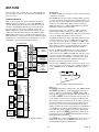
Internal Memory DMA Port (IDMA Port; Host Memory
Mode)
The IDMA Port provides an efficient means of communication
between a host system and the ADSP-2189M. The port is used
to access the on-chip program memory and data memory of the
DSP with only one DSP cycle per word overhead. The IDMA
port cannot, however, be used to write to the DSP’s memorymapped control registers. A typical IDMA transfer process is
described as follows:
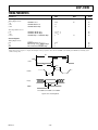
Table VI. Data Formats
Word Size
Alignment
00
01
10
11
Program Memory
Data Memory
Data Memory
Data Memory
24
16
8
8
Full Word
Full Word
MSBs
LSBs
When the BWCOUNT register is written with a nonzero value
the BDMA circuit starts executing byte memory accesses with
wait-states set by BMWAIT. These accesses continue until the
count reaches zero. When enough accesses have occurred to
create a destination word, it is transferred to or from on-chip
memory. The transfer takes one DSP cycle. DSP accesses to
external memory have priority over BDMA byte memory
accesses.
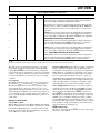
The BMWAIT field, which has four bits on ADSP-2189M,
allows selection of up to 15 wait-states for BDMA transfers.
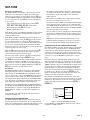
The BDMA circuit supports four different data formats which
are selected by the BTYPE register field. The appropriate number of 8-bit accesses are done from the byte memory space to
build the word size selected. Table VI shows the data formats
supported by the BDMA circuit.
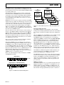
Internal
Memory Space
The source or destination of a BDMA transfer will always be
on-chip program or data memory.
The BDMA overlay bits specify the OVLAY memory blocks to
be accessed for internal memory.
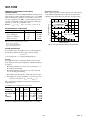
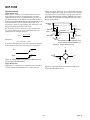
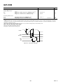
Figure 9. BDMA Control Register
BTYPE
The BWCOUNT register is updated after each transfer so it can
be used to check the status of the transfers. When it reaches
zero, the transfers have finished and a BDMA interrupt is generated. The BMPAGE and BEAD registers must not be accessed
by the DSP during BDMA operations.
The BDMA Context Reset bit (BCR) controls whether the
processor is held off while the BDMA accesses are occurring.
Setting the BCR bit to 0 allows the processor to continue operations. Setting the BCR bit to 1 causes the processor to stop
execution while the BDMA accesses are occurring, to clear the
context of the processor, and start execution at address 0 when
the BDMA accesses have completed.
BTYPE
BDMA
OVERLAY
BITS
BDMA accesses can cross page boundaries during sequential
addressing. A BDMA interrupt is generated on the completion
of the number of transfers specified by the BWCOUNT register.
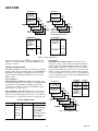
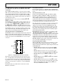
1. Host starts IDMA transfer.
2. Host checks IACK control line to see if the DSP is busy.
Unused bits in the 8-bit data memory formats are filled with 0s.
The BIAD register field is used to specify the starting address
for the on-chip memory involved with the transfer. The 14-bit
BEAD register specifies the starting address for the external byte
memory space. The 8-bit BMPAGE register specifies the starting page for the external byte memory space. The BDIR register
field selects the direction of the transfer. Finally, the 14-bit
BWCOUNT register specifies the number of DSP words to
transfer and initiates the BDMA circuit transfers.
3. Host uses IS and IAL control lines to latch either the DMA
starting address (IDMAA) or the PM/DM OVLAY selection
into the DSP’s IDMA control registers. If Bit 15 = 1, the
value of bits 7:0 represent the IDMA overlay: Bits 14:8 must
be set to 0. If Bit 15 = 0, the value of bits 13:0 represent the
starting address of internal memory to be accessed and Bit 14
reflects PM or DM for access.
4. Host uses IS and IRD (or IWR) to read (or write) DSP internal memory (PM or DM).
5. Host checks IACK line to see if the DSP has completed the
previous IDMA operation.
6. Host ends IDMA transfer.
–10–
REV. A