1
Memory Interface
10.1
10
OVERVIEW
The ADSP-2100 family has a modified Harvard architecture in which data
memory stores data and program memory stores both instructions and
data. Each processor contains on-chip RAM and/or ROM, so that a
portion of the program memory space and a portion of the data memory
space reside on-chip. Each processor (except the ADSP-2181) also has a
boot memory space in addition to the data and program spaces. The
ADSP-2181 has a byte memory space instead of the boot memory space.
The boot memory space and byte memory space can be used to load onchip program memory with code from an external EPROM at reset.
In each ADSP-2100 family device, memory is connected with the internal
functional units by four on-chip buses: the data memory address bus
(DMA), data memory data bus (DMD), program memory address bus
(PMA), and program memory data bus (PMD). The internal PMA bus and
DMA bus are multiplexed into a single address bus which is extended offchip. Likewise, the internal PMD bus and DMD bus are multiplexed into a
single external data bus. The sixteen MSBs of the external data bus are
used as the DMD bus: external bus lines D23-8 are used for DMD15-0.
There are three separate memory spaces: data memory, program memory
and boot (or byte) memory. The PMS, DMS, and BMS signals indicate
which memory space is being accessed. Because the program memory and
data memory buses are multiplexed off-chip, if more than one external
transfer must be made in the same instruction there will be an overhead
cycle required. There is no overhead if just one off-chip access (with no
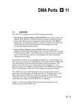
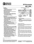
wait states) occurs in any instruction. Figure 10.1 shows the external
memory buses and control signals (for all ADSP-21xx processors except
the ADSP-2181).
All external memories may have automatic wait state generation
associated with them. The number of wait states—each equal to one
instruction cycle—is programmable.
10 – 1
10 Memory Interface
This chapter includes example timing diagrams for the memory interfaces
of the ADSP-21xx processors. For each bus transaction, only the sequence
of events is described; you must consult the processor data sheets for
actual timing parameters. All timing diagrams use CLKOUT as a
reference, which indicates the instruction execution rate.
The memory interfaces of the ADSP-2181 are described separately in the
second half this chapter.
AAA
AAA
AAA
AA
AA
AA
AA
1x CLOCK
or
CRYSTAL
SERIAL
DEVICE
(OPTIONAL)
SERIAL
DEVICE
(OPTIONAL)
ADSP-21xx
14
CLKIN
ADDR13-0
24
BR
BG
SCLK1
RFS1 or IRQ0
TFS1 or IRQ1
DT1 or FO
DR1 or FI
BMS
DATA
e.g. EPROM
2764
27128
27256
27512
CS
A13-0
ADDR
D23-0
DATA
OE
WE
RD
WR
PROGRAM
MEMORY
(OPTIONAL)
CS
A13-0
ADDR
D23-8
PMS
DMS
NOTES
1. Applies to all ADSP-21xx processors except ADSP-2181.
2. ADSP-2171 and ADSP-21msp58/59 use a 1/2x CLKIN signal.
3. Unused data bus lines may be left floating.
4. The two MSBs of the data bus (D23-22) are used to supply the two MSBs of the
boot memory EPROM address. This is only required for the 27256 and 27512.
Figure 10.1 ADSP-21xx System With External Memory
10 – 2
BOOT
MEMORY
OE
MMAP
SPORT 1
ADDR
D15-8
DATA23-0
RESET
IRQ2
SPORT 0
SCLK0
RFS0
TFS0
DT0
DR0
AAAA
AAAA
AAAA
AAAA
AAAA
AAAA
AAAA
AAAA
AAAA
D23-22
XTAL
CLKOUT
A13-0
DATA
OE
WE
CS
DATA
MEMORY
&
PERIPHERALS
(OPTIONAL)
Memory Interface 10
10.2
PROGRAM MEMORY INTERFACE
This section describes the program memory interface of all ADSP-21xx
processors except the ADSP-2181.
The processors address 16K of 24-bit wide program memory, up to 2K
on-chip and the remainder external, using the control lines shown in
Figure 10.1. The processors supply a 14-bit address on the program
memory address bus (PMA) which is driven off-chip on the address bus in
the case of external program memory accesses. Instructions or data are
transferred across the 24-bit program memory data (PMD) bus which is
also multiplexed off-chip. For a dual off-chip data fetch, the data from
program memory is read first, then the data memory data. A program
memory select pin, PMS, indicates that the address bus is being driven
with a program memory address and memory can be selected.
Two control lines indicate the direction of the transfer. Memory read (RD)
is active low signaling a read and memory write (WR) is active low for a
write operation. Typically, you would connect PMS to CE (Chip Enable),
RD to OE (Output Enable) and WR to WE (Write Enable) of your memory.
10.2.1 External Program Memory Read / Write
On-chip memory accesses do not drive any external signals. PMS, DMS,
RD, and WR remain high (deasserted); the address and data buses are
tristated. Off-chip program memory access happens in this sequence:
1. The processor places the address on the PMA bus, which is
multiplexed off-chip, and PMS is asserted.
2.
RD or WR is asserted.
3. Within a specified time, data is placed on the data bus, multiplexed to
the internal PMD bus.
4. The data is read or written and RD (or WR ) is deasserted.
5.
PMS is deasserted.
The basic read and write cycles are illustrated in Figure 10.2 on the next
page. Figure 10.2A shows zero wait states and 10.2B shows the effect of
one wait state.
10 – 3
10 Memory Interface
CLKIN
CLKOUT
PMS
or
DMS
Address
RD
or
WR
Data
In
Data
Out
External Program/Data Memory Read/Write
PWAIT=0, DWAIT=0 (no wait states added)
Figure 10.2A Memory Read And Write, No Wait States
CLKIN
CLKOUT
PMS
or
DMS
Address
RD
or
WR
Data
In
Data
Out
External Program/Data Memory Read/Write
PWAIT=1, DWAIT=1 (one wait state added)
Figure 10.2B Memory Read And Write, One Wait State
10 – 4
Memory Interface 10
The program memory interface can generate 0 to 7 wait states for external
memory devices. The program memory wait state field (PWAIT) in the
system control register is shown in Figure 10.3. PWAIT defaults (after
RESET) to seven wait states for program memory accesses.
System Control Register
0x3FFF
15
14
13
12
11
10
9
8
7
6
5
4
3
2
1
0
PWAIT
(Program Memory Wait States)
Default = 7
Figure 10.3 Program Memory Wait State Field In System Control Register
10.2.2 Program Memory Maps
For all RAM-based processors except the ADSP-2181, the program
memory space is mapped in one of two configurations depending on the
state of the MMAP pin. Figure 10.4 shows these configurations for the
processors with 2K internal program memory (ADSP-2101, ADSP-2111,
ADSP-2171, ADSP-21msp58), and Figure 10.5 shows the same information
for the processors with 1K internal program memory (ADSP-2105,
ADSP-2115).
When MMAP=0, internal RAM occupies 2K words beginning at address
0x0000. In this configuration, the boot loading sequence is automatically
initiated when RESET is released (as described in “Boot Memory
Interface”).
When MMAP=1, words of external program memory begin at address
0x0000 and internal RAM is located in the upper 2K words, beginning at
address 0x3800. In this configuration, program memory is not loaded
although it can be written to and read from under program control.
The program memory space can hold instructions and data intermixed in
any combination. The ADSP-21xx linker determines where to place
relocatable code and data segments. You may specify absolute address
placement for any module or data structure, including the code for the
restart and interrupt vector locations. The restart vector is at program
memory address 0x0000. The interrupt vector locations are given in
Chapter 3 and in Appendix D.
10 – 5
10 Memory Interface
ADSP-2101
ADSP-2111
ADSP-2171
ADSP-21msp58
INTERNAL
RAM
2K
Loaded From
External
Boot Memory
ADSP-2105
ADSP-2115
0x0000
0x0000
INTERNAL RAM
1K
Loaded From
External
Boot Memory
0x07FF
0x0800
0x03FF
0x0400
Reserved
1K
EXTERNAL
14K
INTERNAL RAM
1K
EXTERNAL
0x37FF
0x3800
14K
EXTERNAL
14K
Reserved
1K
2K
MMAP=1
No Booting
0x3FFF
0x3FFF
0x3FFF
Figure 10.4 Program Memory Maps (2K internal RAM)
MMAP=0
MMAP=1
No Booting
Figure 10.5 Program Memory Maps (1K internal RAM)
Internal program memory RAM is fast enough to supply an instruction
and data in the same cycle, eliminating the need for cache memory.
Consequently, if the processor is operating entirely from on-chip memory,
it can fetch two operands and the next instruction on every cycle. It can
also fetch any one of these three from external memory with no
performance penalty.
10.2.3 ROM Program Memory Maps
The ADSP-2172 and ADSP-21msp59 processors contain maskprogrammable ROM on-chip. The program memory maps for these
processors are shown in Figures 10.6 and 10.7. The ADSP-2172 contains 8K
of ROM and the ADSP-21msp59 contains 4K.
On the ADSP-2172 and ADSP-21msp59, the ROM is enabled by setting the
ROMENABLE bit in the Data Memory Wait State control register (at
address DM[0x3FFE]). When the ROMENABLE bit is set to 1, addressing
program memory in the ROM range will access the on-chip ROM. When
ROMENABLE is set to 0, addressing program memory in this range will
access external program memory. The ROMENABLE bit is initialized to 0
after reset unless MMAP and BMODE=1.
10 – 6
0x37FF
0x3800
0x3BFF
0x3C00
INTERNAL
RAM
0x3FFF
EXTERNAL
0x07FF
0x0800
14K
MMAP=0
0x0000
0x0000
Memory Interface 10
2K Internal RAM
Booted
0000
0000
2K Internal RAM
Not Booted
2K External
07FF
0800
07FF
0800
0000
07FF
0800
8K Internal ROM
8K Internal ROM
(ROMENABLE = 1)
(ROMENABLE = 1)
8K Internal ROM
or
or
(ROMENABLE Defaults
to 1 During RESET)
8K External
8K External
(ROMENABLE = 0)
(ROMENABLE = 0)
27FF
2800
27FF
2800
27FF
2800
4K External
6K External
2K Internal RAM
6K External
37FF
3800
3FFF
3FFF
3FFF
MMAP = 1
BMODE = 1
MMAP = 1
BMODE = 0
MMAP = 0
BMODE = 0 or 1
Figure 10.6 ADSP-2172 Program Memory Map
0000
INTERNAL
RAM
LOADED FROM
EXTERNAL
BOOT
MEMORY
INTERNAL
MASK
PROGRAMMED
ROM
17F0 – 17FF
RESERVED
07FF
0800
0800
07FF
INTERNAL
MASK
PROGRAMMED
ROM
17F0 – 17FF
RESERVED
17FF
EXTERNAL
EXTERNAL
EXTERNAL
INTERNAL
RAM NOT
LOADED
ROM ENABLE=1
MMAP=0
0800
17FF
1800
37FF
3FFF
3800
3FFF
3FFF
ROM ENABLE=0
MMAP=0
0000
EXTERNAL
EXTERNAL
07FF
1800
0000
0000
INTERNAL
RAM
LOADED FROM
EXTERNAL
BOOT
MEMORY
ROM ENABLE=1
MMAP=1
37FF
INTERNAL
RAM
3800
NOT
LOADED
3FFF
ROM ENABLE=0
MMAP=1
Figure 10.7 ADSP-21msp59 Program Memory Map
10 – 7
10 Memory Interface
When the MMAP and BMODE pins both are set to 1, the ADSP-2172 (or
ADSP-21msp59) will operate in standalone ROM execution mode. When
MMAP=1 and BMODE=1, the ROM is automatically enabled and
execution begins from program memory location 0x0800 at the start of
ROM. This lets an embedded design operate without external memory
components. To operate in this mode, the ROM-coded program must copy
an interrupt vector table to the appropriate locations in program memory
RAM. In this mode, the ROMENABLE bit defaults to 1 during reset.
Table 10.1 summarizes the booting and startup execution modes for the
ADSP-2172 and ADSP-21msp59.
BMODE = 0
BMODE = 1
MMAP = 0
Boot from EPROM,
then execution starts
at internal RAM
location 0x0000
Boot from HIP, then
execution starts at
internal RAM location
0x0000
MMAP = 1
No booting, execution
starts at external memory
location 0x0000
Standalone mode,
execution starts at
internal ROM location
0x0800
Table 10.1 Booting Mode for ADSP-2172, ADSP-21msp59
The ADSP-216x processors are memory-variant versions of the ADSP-2101
and ADSP-2103 that contain factory-programmed on-chip ROM program
memory. The ADSP-2161, ADSP-2163, and ADSP-2165 are 5.0V supply
processors based on the ADSP-2101. The ADSP-2162, ADSP-2164, and
ADSP-2166 are 3.3V supply processors based on the ADSP-2103. These
devices offer different amounts of on-chip memory for program and data
storage, as shown in Table 10.2.
Feature
2161
2162
2163
2164
2165
2166
Data Memory (RAM)
Program Memory (ROM)
Program Memory (RAM)
1
1
1
1
4K
12K
1K
4K
12K
1K
⁄2K
8K
–
⁄2K
8K
–
⁄2K
4K
–
⁄2K
4K
–
Table 10.2 ADSP-216x ROM-Programmed Processors
Figures 10.8, 10.9, and 10.10 show the program memory maps for the
ADSP-2161/62, ADSP-2163/64, and ADSP-2165/66, respectively.
10 – 8
Memory Interface 10
0x0000
0x0000
2K
EXTERNAL
8K
INTERNAL
ROM
6K
INTERNAL
ROM
0x0000
0x07FF
0x0800
4K
INTERNAL
ROM
0x1FF0
Reserved
2K
EXTERNAL
2K
INTERNAL
ROM
0x0FF0
0x1FF0
Reserved
Reserved
0x1FFF
0x2000
0x1FFF
0x2000
6K
EXTERNAL
8K
EXTERNAL
2K
INTERNAL
ROM
0x3FFF
MMAP=0
0x0FFF
0x1000
0x37FF
0x3800
0x3FFF
0x3FFF
MMAP=0
Figure 10.8 ADSP-2161/62 Program Memory Maps
0x07FF
0x0800
0x0FF0
Reserved
0x0FFF
0x1000
10K
EXTERNAL
12K
EXTERNAL
MMAP=1
0x0000
2K
INTERNAL
ROM
0x37FF
0x3800
0x3FFF
MMAP=1
Figure 10.9 ADSP-2163/64 Program Memory Maps
0000
0000
2K
EXTERNAL
07FF
0800
12K x 24
INTERNAL
ROM
10K X 24
INTERNAL
ROM
2FFF
3000
2FFF
3000
1K x 24 RAM
1K x 24 RAM
33FF
3400
RESERVED
2K x 24
EXTERNAL
RESERVED
37FF
3800
3FFF
MMAP=0
33FF
3400
2K x 24
INTERNAL
ROM
37FF
3800
3FFF
MMAP=1
Figure 10.10 ADSP-2165/66 Program Memory Maps
10 – 9
10 Memory Interface
10.3
DATA MEMORY INTERFACE
This section describes the data memory interface of all ADSP-21xx
processors except the ADSP-2181.
The processors supply a 14-bit address on the data memory address bus
(DMA) which is multiplexed off-chip. Data is transferred across the upper
16 bits of the 24-bit memory data bus, which is also multiplexed off-chip.
A data memory select pin, DMS, indicates that the address bus is being
driven with a data memory address and memory can be selected.
Two control lines indicate the direction of the transfer. Memory read (RD)
is active low signaling a read and memory write (WR) is active low for a
write operation. Typically, you would connect DMS to CE (Chip Enable),
RD to OE (Output Enable) and WR to WE (Write Enable) of your memory.
10.3.1
External Data Memory Read/Write
Internal data memory accesses are transparent to the external memory
interface. Only off-chip accesses drive the memory interface. Off-chip data
memory accesses follow the same sequence as off-chip program memory
accesses, namely:
1. The processor places the address on the DMA bus, which is
multiplexed off-chip, and DMS is asserted.
2.
RD or WR is asserted.
3. Within a specified time, data is placed on the data bus, multiplexed to
the internal DMD bus.
4. The data is read or written and RD (or WR ) is deasserted.
5.
DMS is deasserted.
The basic read and write cycles are illustrated in Figure 10.2.
For a dual off-chip data fetch, the data from program memory is read first,
then the data memory data.
10 – 10
Memory Interface 10
10.3.2
Data Memory Maps
The processors can address a total of 16K words of 16-bit data memory.
On-chip data memory is 1K in size and starts at address 0x3800 on the
ADSP-2101 and ADSP-2111. On-chip data memory is 512 locations in size
on the ADSP-2105 and ADSP-2115, again starting at address 0x3800. Onchip data memory is 2K in size on the ADSP-2171 and ADSP-21msp58/59,
beginning at address 0x3000.
The processors’ control and status registers are mapped into the top 1K of
data memory, addresses 0x3C00-0x3FFF. The rest of the top 1K is
reserved. External data memory is available for additional data storage.
Figures 10.11, 10.12, and 10.13 show the data memory maps for each
ADSP-21xx processor.
1K External
DWAIT0
0x0000
0x0400
1K External
DWAIT1
0x0800
EXTERNAL
RAM
10K External
DWAIT2
0x3000
1K External
DWAIT3
0x3400
1K External
DWAIT4
1K for ADSP-2101
ADSP-2103
ADSP-2111
AAAAA
AAAAA
AAAAA
512 for ADSP-2105
ADSP-2115
ADSP-216x
Memory-Mapped
Control Registers
& Reserved
0x3800
0x3A00
0x3C00
INTERNAL
RAM
0x3FFF
Figure 10.11 Data Memory Map (ADSP-2101, ADSP-2111, ADSP-2105, ADSP-2115, ADSP-2161/62/63/64)
10 – 11
10 Memory Interface
As shown in Figure 10.11, the ADSP-2101, ADSP-2111, ADSP-2105,
ADSP-2115, and ADSP-2161/62/63/64 processors have five external wait
state zones (DWAIT0–DWAIT4). Each of the five zones of external data
memory has its own programmable number of wait states. Wait states are
extra cycles that the processor either waits before latching data (on a read)
or drives the data (on a write). This means that one zone of memory could
be used for working with memory-mapped peripherals of one speed
while another zone was used with faster or slower peripherals. Similarly,
slower and faster memories can be used for different purposes, as long as
they are located in different zones of the data memory map.
As shown in Figures 10.12 and 10.13, the ADSP-2171, ADSP-21msp58/59,
and ADSP-2165/66 processors each have three wait state zones for
external data memory.
0000
DWAIT 0
(1K External)
DWAIT 1
(1K External)
12K External
0000
03FF
0400
07FF
0800
DWAIT 2
(10K External)
2FFF
3000
2FFF
3000
2K Internal
Data RAM
37FF
3800
1K Reserved
Memory Mapped
Registers/Reserved
No Wait States
3BFF
3C00
3FFF
Data Memory
3FFF
Wait States
Figure 10.12 Data Memory Map (ADSP-2171, ADSP-21msp58/59)
10 – 12
Memory Interface 10
0x0000
1K External
DWAIT0
0x0400
1K External
DWAIT1
0x0800
EXTERNAL
RAM
6K External
DWAIT2
0x2000
4K x 16 Internal
INTERNAL
RAM
0x3000
4K x 16
Memory Mapped
Registers
and Reserved
0x3FFF
Figure 10.13 Data Memory Map (ADSP-2165/66)
The Data Memory Waitstate control register has a separate field for each zone
of external memory. Each 3-bit field specifies the number (0-7) of wait states
for the corresponding zone of memory; all zones default to 7 wait states after
RESET. Figure 10.14 shows this control register for the ADSP-2101, ADSP-2111,
ADSP-2105, ADSP-2115, and ADSP-2161/62/63/64 processors. Figure 10.15
shows the register for the ADSP-2171/72 and ADSP-21msp58/59 processors;
on the ADSP-2172 and ADSP-21msp59, one bit in this register is used to enable
or disable the on-chip ROM.
10 – 13
10 Memory Interface
15
14
13
12
11
10
9
8
7
6
5
4
3
2
1
0
0
1
1
1
1
1
1
1
1
1
1
1
1
1
1
1
DWAIT4
DWAIT3
DWAIT2
DWAIT1
DM(0x3FFE)
DWAIT0
Figure 10.14 Data Memory Waitstate Control Register (ADSP-2101, ADSP-2111,
ADSP-2105, ADSP-2115, ADSP-2161/62/63/64)
15
14
13
12
11
10
9
8
7
6
5
4
3
2
1
0
0
0
0
0
0
0
0
1
1
1
1
1
1
1
1
1
DWAIT2
DWAIT1
DM(0x3FFE)
DWAIT0
ROM Enable (ADSP-2172, ADSP-21msp59 only)
1=enable
0=disable
Figure 10.15 Data Memory Waitstate Control Register (ADSP-2171/72, ADSP-21msp58/59)
10.3.3
Memory-Mapped Peripherals
Peripherals requiring parallel communications and other types of devices
can be mapped into external data memory. Communication takes the form
of reading and writing the memory locations associated with the device.
Some A/D and D/A converters require this type of interface. The .PORT
directives in the System Builder and Assembler modules of the ADSP-2100
Family Development Software support this mapping.
Communication with a memory-mapped device consists simply of reading
and writing the appropriate locations. By matching the access times of the
external devices to the wait states specified for their zone of data memory,
you can easily interface a variety of devices.
The 16 MSBs of the external data bus (D23-8) are connected to the 16 LSBs of
the internal DMD bus, so D23-8 should be used for 16-bit peripherals.
10 – 14
Memory Interface 10
10.4
BOOT MEMORY INTERFACE
This section describes the boot memory interface of all ADSP-21xx
processors except the ADSP-2181.
The entire internal program memory, or any portion of it, can be loaded
from an external source using a boot sequence. To interface with
inexpensive EPROM, the processor loads instructions one byte at a time.
Automatic booting at reset depends on the state of the MMAP pin at the
time of processor reset. The boot sequence occurs if the MMAP pin is 0.
The boot sequence can also be initiated after reset by software.
The ADSP-2111, ADSP-2171, and ADSP-21msp5x processors, which
include a Host Interface Port (HIP), can boot using either the memory
interface or the HIP (from a host computer). The state of the BMODE pin
determines which method is used: the memory interface if BMODE=0, or
the HIP if BMODE=1. Booting through the HIP is described in Chapter 7.
BR is recognized during the booting sequence. The bus is granted after
completion of loading the current byte.
The ADSP-216x contain on-chip program memory ROM; on these devices,
no booting occurs.
10.4.1 Boot Pages
Boot memory is organized into eight pages, each of which can be 8K bytes
long. Every fourth byte of a page is an “empty” byte, except the first one,
which contains the page length. Each set of three bytes between successive
empty bytes contains an instruction. The page length is read first and then
bytes are loaded from the top of the page downwards. This results in
shorter booting times for shorter pages.
The length of the boot page is given as:
page length = (number of 24-bit PM words / 8) – 1
That is, a page length of 0 causes the boot address generator to generate
byte addresses for 8 words which reside in 32 sequential ROM locations.
The PROM Splitter utility, part of the ADSP-2100 Family Development
Software tools, calculates the proper page length for your program and
orders the bytes of your program as shown in Figure 10.16 (on the next
page).
10 – 15
10 Memory Interface
Address
0000
Word 0: USB
0001
Word 0: MSB
0002
Word 0: LSB
0003
Page Length
0004
Word 1: USB
001B
Not Used
001C
001D
Word 7: USB
Word 7: MSB
001E
Word 7: LSB
001F
Not Used
Figure 10.16 EPROM Contents
10.4.2 Powerup Boot & Software Reboot
Upon a hardware or software reset, the boot sequence occurs if the MMAP
pin is a logical 0. The boot sequence on reset always loads boot page 0.
After reset, boot loading can occur under program control from any one of
up to 8 different boot pages. The boot page select field (BPAGE) in the
memory-mapped System Control Register (see Figure 10.17) specifies
which boot page is to be loaded. To boot from a specific boot page, set
BPAGE to the desired page number and, in the same memory-mapped
register, set the boot force bit (BFORCE). When the boot force bit is set, the
software-forced booting sequence starts. Except for the page selection and
(possibly) the number of wait states, there is no difference between a
software-forced boot sequence and a reset boot sequence.
Tables 9.2–9.7 in the System Interface chapter show the state of the
processor control registers after a reset and after a software reboot.
Essentially, the processor’s control state is saved, but stacks are cleared
and execution starts at the restart vector, at program memory location
0x0000.
10 – 16
Memory Interface 10
System Control Register
15
14
13
0
0
0
12
11
10
9
BFORCE
(Boot Force Bit)
8
7
6
5
4
3
0
0
0
0/1
1
1
2
1
0
DM(0x3FFF)
BWAIT (Boot Wait States)
Default=3 for ADSP-21xx
Default=7 for ADSP-2171, ADSP-21msp58
BPAGE (Boot Page Select)
Default = 0
Figure 10.17 Boot Control Fields In System Control Register
10.4.3 Boot Memory Access
The processor can boot its internal memory from a single byte-wide
CMOS EPROM, such as the 27C64 and 27C512. A low-cost, commoditygrade EPROM with an industry-standard access time can be used. The
number of wait states for the boot memory access is selected in the BWAIT
field of the System Control Register (see Figure 10.17). This field can be set
to any value from 0 to 7 in order to generate 0 to 7 wait states. The default
value at reset is 3 wait states on the ADSP-2101, ADSP-2105, ADSP-2111,
and ADSP-2115. BWAIT defaults to 7 wait states on the ADSP-2171 and
ADSP-21msp58.
Timing of the boot memory access is identical to that of external program
memory or external data memory accesses, except that the active strobe is
BMS rather than PMS or DMS. To address eight pages of 8K bytes each, 16
bits are needed. The least significant 14 bits are output on the 14-bit
address bus, and the most significant 2 bits are output on the 2 MSBs of
the data bus during a boot memory access. Data is read from the middle
eight bits of the data bus.
10.4.4 Boot Loading Sequence
The order in which the processor loads data into its internal memory
during a boot operation is unimportant in most applications. The boot
loading sequence is explained in this section for those instances in which
the order is relevant, for instance when a latch is providing data rather
than an EPROM.
10 – 17
10 Memory Interface
To execute the boot operation, the boot address generator generates the
appropriate byte addresses and loads internal program memory with the
contents of the EPROM. The internal program memory is loaded
beginning with the high addresses. For example, assume that eight 24-bit
words are loaded into the processor during the booting process. The first
word written into program memory is written to address 0x0007. The last
word loaded is written to internal program memory address 0x0000.
The boot address is made up of several values, as shown in Figures 10.18
and 10.19: the 3-bit page number (from BPAGE in the system control
register); the 8-bit page length, which is always read first (from the fourth
byte of the page); a 3-bit word counter value; and a 2-bit code whose value
determines which byte of the word is being addressed.
The last 24-bit word (instruction or data value) is loaded into the
processor first. The byte loading order is: upper byte, lower byte, middle
byte. The word pointer is then decremented. This addresses the second-tolast 24-bit word in the EPROM.
For example, to boot from page 0 the shortest allowable page (with eight
24-bit words corresponding to a page length of 0), the following addresses
would be generated (see Figure 10.20):
1. The first address generated is 0x0003 which reads the page length.
2. The next address generated in this example is address 0x001C. This is
the upper byte of the last word.
3. The byte code is then updated to specify the lower byte (the final two
bits are 10) and the address generated is 0x001E.
4. The byte address changes again, this time to address the middle byte
(the two bit code is 01) and the address generated is 0x001D.
5. Once all three bytes are loaded, the word counter is decremented. The
three succeeding byte addresses generated are 0x0018, 0x001A, and
0x0019.
6. The word counter is decremented again and the next set of byte
addresses generated is 0x0014, 0x0016, and 0x0015. This process
continues until word 0 is loaded.
The contents of the EPROM, the byte addresses, and the order of
addresses generated is shown in Figure 10.20.
10 – 18
Memory Interface 10
Byte Address
Word Pointer
15 14
13
12
11
Page #
10
9
8
7
6
5
4
3
2
1
0
Counter
8-Bit Page Length
}
2-bit byte code: USB = 00
MSB = 01
LSB = 10
Figure 10.18 Boot Memory Address
15 14
13
12
11
10
9
8
7
6
5
4
3
2
1
0
Page #
8-Bit Page Length
1
1 1
0
0
Page #
8-Bit Page Length
1
1 1
1
0
Page #
8-Bit Page Length
1
1 1
0
1
Page #
8-Bit Page Length
1
1 0
0
0
Page #
8-Bit Page Length
1
1 0
1
0
Page #
8-Bit Page Length
1
1 0
0
1
Page #
8-Bit Page Length
1
0 1
0
0
1st Word
2nd Word
etc.
Figure 10.19 Boot Memory Addresses
10 – 19
10 Memory Interface
Address
EPROM
0000
0001
Word 0: USB
Word 0: MSB
0002
Word 0: LSB
0003
0004
Page Length
Word 1: USB
0005
Word 1: MSB
0006
Word 1: LSB
0007
Not Used
0018
Word 6: USB
5th
0019
Word 6: MSB
Word 6: LSB
7th
001A
001B
Order
Addressed
(bytes)
1st
2nd word loaded
6th
Not Used
001C
Word 7: USB
2nd
001D
001E
Word 7: MSB
4th
Word 7: LSB
3rd
001F
Not Used
1st word loaded
Page#=0, Pagelength=0
Figure 10.20 Example of Boot Loading Order (with Page#=0, Pagelength=0)
10 – 20
Memory Interface 10
10.5
BUS REQUEST / GRANT
This section describes the bus request and grant feature of all ADSP-21xx
processors, including the ADSP-2181.
The ADSP-21xx can relinquish control of its data and address buses to an
external device. The external device requests the bus by asserting (low) the
bus request signal, BR. BR is an asynchronous input. If the ADSP-21xx is not
performing an external access, it responds to the active BR input in the
following processor cycle by:
• tristating the data and address buses and the xMS, RD, WR output drivers,
• asserting the bus grant (BG) signal, and
• halting program execution (unless Go Mode is enabled).
If Go Mode is enabled, the ADSP-21xx continues to execute instructions from
its internal memory. It will not halt program execution until it encounters an
instruction that requires an external access. (An “external access” may be
either a memory device access or, on the ADSP-2181, a memory overlay
access, BDMA access, or I/O space access.)
If Go Mode is not enabled, the ADSP-21xx always halts before granting the
bus. The processor’s internal state is not affected by granting the bus, and the
serial ports and host interface port (on the ADSP-2111, ADSP-2171,
ADSP-21msp5x) remain active during a bus grant, whether or not the
processor core halts.
If the ADSP-21xx is performing an external access when the BR signal is
asserted, it will not grant the buses until the cycle after the access completes.
The sequence of events is illustrated in Figure 10.21. The entire instruction
does not need to be completed when the bus is granted. If a single instruction
requires two external accesses, the bus will be granted between the two
accesses. The second access is performed after BR is removed.
When the BR input is released, the ADSP-21xx releases the BG signal,
reenables the output drivers and continues program execution from the point
where it stopped. BG is always deasserted in the same cycle that the removal
of BR is recognized. Refer to the data sheet for exact timing relationships.
The bus request feature operates at all times, including when the processor is
booting and when RESET is active. During RESET, BG is asserted in the same
cycle that BR is recognized. During booting, the bus is granted after
completion of loading of the current byte (including any wait states). Using
bus request during booting is one way to bring the booting operation under
control of a host computer.
10 – 21
10 Memory Interface
The ADSP-2171 and ADSP-2181 processors have an additional feature, the
Bus Grant Hung (BGH) output, which lets them operate in a
multiprocessor system with a minimum number of wasted cycles. The
BGH pin asserts when the ADSP-21xx is ready to execute an instruction
but is stopped because the external bus is granted to another device. The
other device can release the bus by deasserting bus request. Once the bus
is released, the ADSP-21xx deasserts BG and BGH and executes the
external access. Figure 10.22 shows timing for the BGH signal.
CLKOUT
If no memory access is in progress, BG is
asserted in the cycle after BR is recognized:
BR
BG
PMS
DMS
BMS
If a memory access is in progress, BG is asserted in
the cycle after the access is completed:
BR
BG
PMS
DMS
BMS
Figure 10.21 Bus Request (with and without external access)
10 – 22
Memory Interface 10
CLKOUT
BR
xMS
RD
WR
BG
BGH
Figure 10.22 Bus Grant Hung (BGH) Timing (ADSP-2171, ADSP-2181 only)
10.6
ADSP-2181 MEMORY INTERFACES
The ADSP-2181 has the same modified Harvard architecture for internal
memory as the other processors of the ADSP-2100 family. In this
architecture, Data Memory stores data values and Program Memory
stores both instructions and data. The ADSP-2181 has as its full base
memory on-chip: 16K x 24-bit words of internal program memory RAM
and 16K x 16-bit words of internal data memory RAM.
There are four separate memory spaces: data memory, program memory,
byte memory, and I/O memory. To provide external access to these
memory spaces, the ADSP-2181 extends the internal address and data
buses off-chip and provides the PMS, DMS, BMS, and IOMS select lines.
The PMS, DMS, BMS, and IOMS signals indicate which memory space is
being accessed.
The composite memory space (and its CMS select line) lets a single offchip memory be accessed as multiple memory spaces. The Composite
Memory Select register lets you define which memory spaces are selected
by the CMS signal.
10 – 23
10 Memory Interface
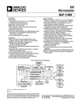
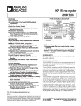
Figure 10.23 shows the external memory buses and control signals in an
ADSP-2181 system. Two control lines determine the direction of external
memory transfers: RD is active low signaling a read and WR is active low
for a write operation. Typically, you would connect RD to OE (Output
Enable) and WR to WE (Write Enable) of your memory.
Internal memory accesses do not drive any external signals: PMS, DMS,
BMS, IOMS, RD , and WR remain high (deasserted), and the address and
data buses are tristated.
ADSP-2181
1/2x CLOCK
or
CRYSTAL
CLKIN
XTAL
14
ADDR13-0
A13-0
D 23-16
FL0-2
PF0-7
24
D15-8
DATA23-0
A0-A21
BYTE
MEMORY
DATA
IRQ2
IRQE
IRQL0
CS
BMS
A 10-0
IRQL1
ADDR
D 23-8
SPORT 1
SERIAL
DEVICE
SCLK1
RFS1 or IRQ0
TFS1 or IRQ1
DT1 or FO
DR1 or FI
SPORT 0
SCLK0
RFS0
TFS0
DT0
DR0
SERIAL
DEVICE
SYSTEM
INTERFACE
or
µCONTROLLER
IDMA PORT
IRD
IWR
IS
IAL
IACK
16
IAD15-0
DATA
2048 Locations
IOMS
CS
A 13-0
ADDR
D23-0
PMS
DMS
CMS
BR
BG
BGH
PWD
PWDACK
Figure 10.23 ADSP-2181 System Diagram
10 – 24
I/O SPACE
(PERIPHERALS)
DATA
OVERLAY
MEMORY
Two 8K
PM Segments
Two 8K
DM Segments
Memory Interface 10
Unlike other processors of the ADSP-2100 family, the ADSP-2181 supports
several additional memory interfacing features. These features include:
• External Overlay Memory in 8K segments: these segments can be
swapped for the upper 8K of internal program memory or lower 8K of
data memory.
• I/O Memory space: this memory space is for peripheral I/O, has 2K
(16-bit wide) locations, and has four user-assignable waitstate ranges.
• Byte Memory & Byte Memory DMA (BDMA): this memory space can
address up to 4M bytes. The byte memory interface supports booting
from and runtime access to inexpensive 8-bit memories. The DMA
feature lets you define the number of memory locations the DSP will
transfer to/from internal memory in the background while continuing
foreground processing.
• Internal Direct Memory Access (IDMA) Port: this port supports booting
from and runtime access to host systems (for example, PC Bus Interface
ASICs). The DMA feature of this port lets you define the number of
memory locations the DSP will transfer to/from internal memory in the
background while continuing foreground processing.
For complete information on the BDMA port, including booting, and IDMA
port, refer to the DMA Ports chapter of this manual.
The ADSP-2181 uses a half-instruction-rate clock input from which it
generates a full-instruction-rate internal clock. For example, from a
16.67 MHz clock input (CLKIN) the ADSP-2181 generates a 33.33 MHz
instruction rate clock. All timing diagrams for the processor use the fullinstruction-rate output clock (CLKOUT) as a reference.
All external memories may have automatic wait state generation associated
with them. The number of wait states—each equal to one instruction cycle—
is programmable.
10.6.1
ADSP-2181 Program Memory Interface
The ADSP-2181 processor addresses its 16K of internal program memory as
well as two 8K external program memory overlays. All program memory is
24 bits wide. Up to two accesses to internal program memory can be
completed per instruction cycle; this lets the DSP complete all operations in
a single cycle. The PWAIT field of the System Control Register (shown in
Figure 10.24) sets the number of waitstates for each access to program
memory overlays. PWAIT defaults (after reset) to seven.
10 – 25
10 Memory Interface
System Control Register
15
14
13
12
11
10
9
8
7
6
5
0
0
0
0
0
1
00
0
0
00
00
01
4
01 0
3
2
1
1
1
0
1
DM (0x3FFF)
SPORT0 Enable
1 = enabled, 0 = disabled
SPORT1 Enable
1 = enabled, 0 = disabled
PWAIT
Program Memory Overlay Wait States
SPORT1 Configure
1 = serial port
0 = FI, FO, IRQ0, IRQ1, SCLK
Figure 10.24 PWAIT Field in System Control Register
The on-chip program memory and overlays can hold instructions and
data intermixed in any combination. The ADSP-21xx linker determines
where to place relocatable code and data segments. You may specify
absolute address placement for any module or data structure, including
the code for the restart and interrupt vector locations. The restart vector is
at program memory address 0x0000.
The ADSP-2181’s MMAP pin lets you select from two program memory
configurations. The MMAP pin also controls whether the ADSP-2181
boots after RESET is released. Figure 10.25 shows the MMAP options and
the resulting memory maps for program memory.
The program memory overlay select register (PMOVLAY) lets you choose
a memory overlay to map from address PM(0x2000) to address
PM(0x3FFF). The memory mapped to this space and corresponding
PMOVLAY register values are shown in Figure 10.25. Table 10.3 shows
how PMOVLAY relates to the addressing of memory locations (with
address line A13).
PMOVLAY
0
1
Memory
Internal
External overlay 1
A13
—
0
2
External overlay 2
1
A12:0
—
13 LSBs of address between
0x2000 and 0x3FFF
13 LSBs of address between
0x2000 and 0x3FFF
Table 10.3 PMOVLAY and Program Memory Overlay Addressing
10 – 26
Memory Interface 10
MMAP = 0
Program Memory
MMAP = 1
Address
0x3FFF
8K Internal
(PMOVLAY = 0)
Program Memory
Address
0x3FFF
8K Internal
(PMOVLAY = 0)
or
External 8K
(PMOVLAY = 1 or 2)
0x2000
0x1FFF
0x2000
0x1FFF
8K External
8K Internal
0x0000
0x0000
Figure 10.25 ADSP-2181 Program Memory Map
The following example instructions demonstrate how to use the
PMOVLAY register.
PMOVLAY=DM(0x1234);
}
{type 3 instruction, PMOVLAY is loaded
{ with the contents of address
DM(0x1234)}
PMOVLAY=2;
{type 7 instruction, PMOVLAY is loaded }
{ with the value 2. }
PMOVLAY=AX0;
{PMOVLAY is loaded from AX0 register.}
AX0=PMOVLAY;
{AX0 is loaded from PMOVLAY register.}
If you are using a system design that sets MMAP=1, note that the first 8K is
used to support a single segment of external memory. This allows an
external ROM-based system to operate properly. In this mode, the external
program memory address always has A13 set to 0 and 8K of internal PM is
available. Set PMOVLAY=0 and MMAP=1. This mode is available on other
10 – 27
10 Memory Interface
ADSP-2100 family processors.
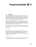
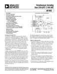
Figure 10.26 shows a memory design that provides full external program
and data memory overlays for an ADSP-2181 processor, assuming that
MMAP=0. The important points to note about this design are:
• Three 32K x 8-bit SRAMs are required for full external program and
data memory overlays; glue logic is not required.
• Four control lines are required for read (RD), write (WR), chip select
(CMS), and data/program memory select (PMS or DMS).
• Composite Memory Select (CMSSEL) is configured to assert the CMS
control line when Program Memory Select (PMS) or Data Memory
Select (DMS) are asserted.
• The order of overlays stored in this design (from lowest address to
highest) is PM Overlay 1, PM Overlay 2, DM Overlay 1, and DM
Overlay 2. Address line 13 (A13) of the ADSP-2181 selects between
overlay 1 or 2. Figure 10.27 shows a memory map of this design.
ADDR 0 - 13
A0 - 13
DATA 0 - 7
D0 - 7
ADDR 0 - 13
A0 - 13
32K x 8 BIT
SRAM
DATA 8 - 15
D0 - 7
ADDR 0 - 13
A0 - 13
32K x 8 BIT
SRAM
CS
OE
WE
A14
CMS
RD
WR PMS
D0 - 7
32K x 8 BIT
SRAM
CS
OE
WE A14
CS
OE
WE A14
CMS
RD
WR PMS
CMS
RD
WR PMS
Figure 10.26 Example Program and Data Memory Overlay Design
10 – 28
DATA 16 - 23
Memory Interface 10
DM Overlay 2
A13 = 1
DM Overlay 1
A13 = 0
PM Overlay 2
A13 = 1
PM Overlay 1
A13 = 0
PMS = 1
PMS = 0
Figure 10.27 Memory Overlay Addressing For Example Design
There are some restrictions on using program memory overlays:
• The ADSP-2181’s program sequencer does not consider the value in the
PMOVLAY register. Switching pages during operations that are sensitive to
the current PMOVLAY register value can result in program execution errors.
For example, if your program is performing a loop operation on one of the
external overlays and the program changes to another external or internal
overlay, an incorrect loop operation could occur.
• The contents of the PMOVLAY register are not automatically saved and
restored on the processors status stack when the processor responds to an
interrupt. If your program uses overlays, you must save and restore the
10 – 29
10 Memory Interface
contents of PMOVLAY as part of your interrupt service routine.
10.6.2
ADSP-2181 Data Memory Interface
The ADSP-2181 addresses 16K x 16-bit wide internal data memory and
two 8K x 16-bit wide external data memory overlays. All accesses to
internal data memory are completed in a single processor instruction
cycle. The DWAIT field of the Waitstate Control Register (shown in Figure
10.28) sets the number of waitstates for each access to data memory
overlays. Figure 10.29 shows the data memory map of the ADSP-2181.
The processor’s memory-mapped control/status registers are mapped
into the top locations of internal data memory, addresses 0x3FE0-0x3FFF.
Most of the ADSP-2181’s control registers correspond to those found on
other ADSP-21xx processors. Note that the ADSP-2181’s System Control
Register does not have the boot memory control fields found on other
ADSP-21xx processors. Also note that the Waitstate Control Register
Wait State Control Register
15
14
13
12
11
10
9
8
7
6
5
4
3
2
1
0
0
1
1
1
1
1
1
1
1
1
1
1
1
1
1
1
DWAIT
IOWAIT3
IOWAIT2
Figure 10.28 ADSP-2181 Wait State Control Register
Data Memory
32 Memory-Mapped
Control Registers
Address
0x3FFF
0x3FE0
0x3FDF
Internal
8160 words
0x2000
0x1FFF
8K Internal
(DMOVLAY=0)
or
External 8K
(DMOVLAY=1,2)
0x0000
10 – 30
Figure 10.29 ADSP-2181 Data Memory Map
IOWAIT1
IOWAIT0
DM(0x3FFE)
Memory Interface 10
includes four fields for the ADSP-2181’s I/O memory space.
The Data Memory overlay select (DMOVLAY) register lets you choose a
memory overlay to map from address DM(0x0000) to address DM(0x1FFF).
The DMOVLAY register is unique to the ADSP-2181. The memory mapped
to this space and corresponding DMOVLAY contents are shown in Figure
10.29. Table 10.4 shows how DMOVLAY relates to memory addressing
(address line A13).
DMOVLAY
0
1
Memory
Internal
External overlay 1
A13
—
0
2
External overlay 2
1
A12:0
—
13 LSBs of address between
0x0000 and 0x1FFF
13 LSBs of address between
0x0000 and 0x1FFF
Table 10.4 DMOVLAY and Data Memory Overlay Addressing
The following example instructions demonstrate how to use the DMOVLAY
register:
DMOVLAY=DM(0x1234);
}
{type 3 instruction, DMOVLAY is loaded
{ with the contents of address
DM(0x1234)}
DMOVLAY=2;
{type 7 instruction, DMOVLAY is loaded }
{ with the value 2. }
DMOVLAY=AX0;
{DMOVLAY is loaded from AX0 register.}
AX0=DMOVLAY;
{AX0 is loaded from DMOVLAY register.}
For an example memory design that provides full external program and
data memory overlays for an ADSP-2181 processor, see the previous section
“Program Memory Interface.”
Two control lines indicate the direction of external transfers. Memory read
(RD) is active low signaling a read and memory write (WR) is active low for
a write operation. Typically, you would connect DMS to CE (Chip Enable),
10 – 31
10 Memory Interface
RD to OE (Output Enable) and WR to WE (Write Enable) of your memory.
10.6.3
ADSP-2181 Byte Memory Interface
The ADSP-2181’s byte memory space is 8 bits wide and can address up to
4M bytes of program code or data. This memory space takes the place of
the boot memory space found on other ADSP-2100 family processors.
Unlike boot memory space, byte memory has read/write access through
the ADSP-2181’s BDMA port.
Byte memory space consists of 256 pages, each containing 16K x 8-bit wide
locations. This memory can be written and read in four different formats:
24-bit, 16-bit, 8-bit MSB alignment, and 8-bit LSB alignment.
Each read/write to byte memory consists of data (on data bus lines 15:8)
and address (on address bus lines 13:0 plus data lines 23:16). The 22-bit
byte memory address lets you access up to 4M bytes of ROM or RAM.
For complete information on the ADSP-2181’s byte memory and BDMA
port, refer to the DMA Ports chapter of this manual.
10.6.4
ADSP-2181 I/O Memory Space
The ADSP-2181 has a dedicated I/O Memory Space instead of the
memory-mapped I/O used on other ADSP-21xx processors. The I/O
memory space consists of 2048 locations with four associated
programmable waitstate regions. Figure 10.30 shows the Wait State
Wait State Control Register
15
14
13
12
11
10
9
8
7
6
5
4
3
2
1
0
0
1
1
1
1
1
1
1
1
1
1
1
1
1
1
1
DWAIT
IOWAIT3
IOWAIT2
Figure 10.30 ADSP-2181 Waitstate Control Register
10 – 32
IOWAIT1
IOWAIT0
DM(0x3FFE)
Memory Interface 10
Control Register and the IOWAIT0-3 bit fields that control I/O memory
waitstate regions.
The Wait State Control Register is divided into the following fields:
• IOWAIT0. This 3-bit field sets the number of waitstates (0-7) for
accesses to I/O memory addresses 0x000–0x1FF.
• IOWAIT1. This 3-bit field sets the number of waitstates (0-7) for
accesses to I/O memory addresses 0x200–0x3FF.
• IOWAIT2. This 3-bit field sets the number of waitstates (0-7) for
accesses to I/O memory addresses 0x400–0x5FF.
• IOWAIT3. This 3-bit field sets the number of waitstates (0-7) for
accesses to I/O memory addresses 0x600–0x7FF.
• DWAIT. This 3-bit field sets the number of waitstates (0-7) for accesses
to external program and data memory overlays.
Note: The PWAIT field of the System Control Register sets the number of
waitstates for access to external program memory overlays.
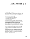
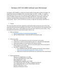
When you connect a parallel I/O device to the ADSP-2181 as shown in
ADDRESS 10:0
or
Decoded
Address Input
DATA 23:8
Codec, A/D, D/A, or
other peripheral device.
IOMS
RD
WR
Figure 10.31 I/O Memory Space Peripheral Connection Example
10 – 33
10 Memory Interface
13
12
11
10
9
8
7
6
5
4
3
2
1
0
0
1
x
0
0
0
0
0
0
0
0
0
0
0
I/O Memory Operation
1 = Write
0 = Read
I/O Memory Address
Figure 10.32 I/O Memory Address Word
Figure 10.31, the address sent to the device appears on the external
address bus as shown in Figure 10.32.
Host interfaces can use the additional communications channel provided
by the ADSP-2181’s I/O memory space. If your system bus interface ASIC
uses a set of data registers for passing control information from the system
bus and must also pass large amounts of sample data, map the control
registers as I/O memory peripherals and transfer the sample data using
IDMA. This combination of the I/O memory and IDMA channels reduces
system bus transfer rate limitations.
Note: As with other ADSP-2100 Family processors, on the ADSP-2181 you
can define memory-mapped I/O ports with the assembler’s .PORT
directive. On the ADSP-2181, this directive defines memory-mapped I/O
ports in external program memory overlays or data memory overlays. If
you want to use this feature, you must make sure at runtime that you are
on the correct program memory overlay or data memory overlay when
accessing the port; the assembler and linker will not flag errors in .PORT
accesses related to overlays because the issue is resolved at runtime. The
“IO” keyword does not work with the .PORT directive; to assign symbolic
10 – 34
Memory Interface 10
labels to I/O memory addresses, use a #define macro. The best use of
the .PORT directive is in porting non-ADSP-2181 applications to the
ADSP-2181; otherwise, use I/O memory space for memory-mapped I/O.
10.6.5
ADSP-2181 Composite Memory Select
The ADSP-2181 has a programmable memory select signal, Composite
Memory Select (CMS ). This signal lets you generate a memory select for
devices mapped to more than one memory space, with the same timing as
other individual memory select signals (PMS, DMS, BMS, and IOMS).
Based on the value of CMSSEL in the Programmable Flag & Composite
Select Control register (see Figure 10.33), the ADSP-2181 asserts CMS
Programmable Flag & Composite Select Control
15
14
13
12
0
1
1
1
11
10
9
8
7
6
5
4
3
2
1
0
0
0
0
0
0
0
0
0
1
0
1
1
IOM
BM
DM
PM
BMWAIT
CMSSEL
1 = Enable CMS
0 = Disable CMS
DM(0x3FE6)
PFTYPE
1 = Output
0 = Input
Figure 10.33 CMSSEL Selection for CMS Signal
when the corresponding memory select signal (or signals) are asserted. Each
xMS signal can be individually enabled. After reset, CMSSEL is initialized to
enable PMS, DMS, and IOMS (with BMS disabled).
Figure 10.26 (earlier in this chapter) shows an example of how to use the
10 – 35
10 Memory Interface
CMS signal. In this system the CMS line drives the chip select for all
three SRAMs. This lets you use three 32K x 8-bit SRAMs, with no glue
logic, for complete program and data memory overlays.
10.6.6
External Memory Read – Overlays & I/O Memory
External memory reads may access either PM overlays, DM overlays, or
I/O memory space. These read operations occur in the following
sequence (see Figure 10.34):
1) The ADSP-2181 executes a read from an external memory address; the
address is driven on the address bus and PMS, DMS, BMS, or IOMS ,
and RD is asserted. (CMS may also be asserted, depending how it is
configured.)
2) The external peripheral drives the data onto the data bus.
3) The ADSP-2181 reads the data and deasserts RD.
WR remains high (deasserted) throughout the external memory read
operation.
Note that ADSP-2181 internal memory accesses do not drive any
CLKOUT
A0 – A13
DMS, PMS,
BMS, IOMS,
or CMS
RD
DATA
Figure 10.34 External Memory Read Timing
10 – 36
Memory Interface 10
external signals: PMS, DMS, IOMS, BMS, CMS, RD, and WR remain high
(deasserted), and the address and data buses are tristated.
10.6.7
External Memory Write – Overlays & I/O Memory
External memory writes may access either PM overlays, DM overlays, or I/O
memory space. These read operations occur in the following sequence (see
Figure 10.35):
1) The ADSP-2181 executes a write to an external memory address; the address
is driven on the address bus, data is driven on the data bus, and PMS, DMS,
BMS, or IOMS, and WR is asserted. (CMS may also be asserted, depending
how it is configured.)
2) The external peripheral stores the data.
3) The ADSP-2181 stops driving the address and data buses and deasserts WR.
CLKOUT
A0 – A13
DMS, PMS,
BMS, IOMS,
or CMS
WR
DATA
Figure 10.35 External Memory Write Timing
RD remains high (deasserted) throughout the external memory write
operation.
10.7
MEMORY INTERFACE SUMMARY (ALL PROCESSORS)
Table 10.5 summarizes the states of the memory interface pins for various
combinations of program memory and data memory accesses. Table 10.6
summarizes the states of the memory interface and control pins during
reset, booting (ADSP-21xx boot memory booting, not ADSP-2181 byte
memory booting), and bus grant.
10 – 37
10 Memory Interface
Access
PMS
DMS
BMS
RD
WR
Address
Data
Internal program
memory only
high
high
high
high
high
tristated
tristated
Internal data
memory only
high
high
high
high
high
tristated
tristated
Internal program
memory, external
data memory
high
low
high
low
(for
read)
low
DM address
(for
write)
DM data
Internal data
memory, external
program memory
low
high
high
low
(for
read)
low
PM address
(for
write)
PM data
External boot
memory
high
high
low
low
(for
read)
high
Boot data,
Boot page
address
Boot address
Table 10.5 Pin States During Memory Accesses
Operation
Address
Data
PMS
DMS
BMS
RD
WR
CLKOUT
SPORTs
BG
Reset
tristated
tristated
high
high
active
tristated
high
Booting*
after Reset
active
active
BMS active
PMS , DMS
RD active
WR high
active
tristated
high
BMS active
PMS , DMS
RD active
WR high
active
active
high
high
Reboot*
active
active
high
BR Asserted
tristated
tristated
tristated
tristated
active
active
low
BR Asserted
tristated
tristated
tristated
tristated
active
tristated
low
during Normal
Operation, Booting*,
or Go Mode
during Reset
Table 10.6 Pin States During Reset, Booting*, and Bus Grant
* ADSP-21xx boot memory booting, not ADSP-2181 byte memory booting.
10 – 38