1
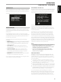
IDENTIFICATION OF CONTROLS
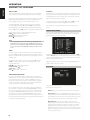
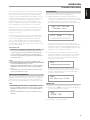
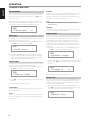
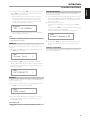
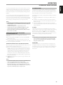
REAR PANEL
ENGLISH
1
2
3
4
5
6
7
8
9
FRANÇAIS
L
R
ZONE 2
SURR-BACK/
ZONE 2
SURR-B/ZONE2
ESPAÑOL
SURR-BACK/
ZONE 2
PORTUGUÊS
10 11 12
13
14
15
16
ITALIANO
ATTENTION!
Please make sure that the T 748 is powered off or unplugged from the mains power source before making any connections. It is also advisable to power
down or unplug all associated components while making or breaking any signal or AC power connections.
DEUTSCH
1 FM ANTENNA TERMINAL
• Connect the supplied lead-type FM antenna to the FM antenna
input. Extend the lead. Experiment freely with your antenna
placement and orientation until you get the clearest sound and
lowest background noise. Fix the antenna in the desired position by
using thumb tacks, push pins or any suitable means.
NEDERLANDS
AM ANTENNA TERMINAL
The AM loop antenna supplied with the T 748 (or a suitable
replacement) is required for AM reception.
• Connect the supplied AM loop antenna to these terminals. If an
external AM antenna is used, make connections to the AM and GND
terminals in accordance with the instructions supplied with the
antenna.
• Testing different positions for the antenna may improve reception;
vertical orientation will usually produce the best results. Antenna
proximity to large metal objects (appliances, radiators) may impair
reception, as will as attempts to lengthen the wire to the loop.
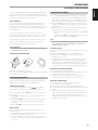
• Refer also to the item about ASSEMBLING THE LOOP ANTENNA at
the LISTENING TO AM/FM RADIO section of the OPERATION page.
SVENSKA
РУССКИЙ
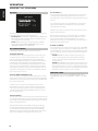
2 AUDIO 1-2/VIDEO 1-2/S-VIDEO
• These comprise the T 748’s other sets of principal input. Connect
these S-Video, composite video, and analog audio input ports to
the corresponding output ports of source components such as DVD
players or cable/satellite boxes.
• AUDIO 2 IN and S-VIDEO IN are the assigned default ports for the
audio/video output of the separately sold NAD IPD (NAD IPD Dock
for iPod) 1, NAD IPD 2 and later variants.
8
3 MONITOR OUT
• Connect to the video input of a monitor/television using quality
dual-RCA cables designed for video signals.
4 AUDIO 3 IN/OUT
• Connect AUDIO 3 OUT to the corresponding analog audio input
of a recording component such as a cassette deck, CD recorder or
to an outboard audio/video processor. Connect AUDIO 3 IN to the
component’s corresponding analog audio output connectors.
• The signal present at the AUDIO 3 OUT is determined by the source
last selected via the front panel Source keys or the AVR 4’s input select
keys with the exception of Source 3 or Source 4. If the default settings
are maintained for both Source 3 and Source 4 (analog audio input is
AUDIO 3) and both their respective digital audio input is set to “Off”,
there will be no output at AUDIO 3 OUT when Source 3 or Source 4 is
selected. This prevents feedback through the recording component
thereby preventing possible damage to your speakers.
5 COMPONENT VIDEO INPUT
• Connect the Component Video Input to Component Video output
of compatible source components, typically a DVD player, BD player,
digital cable box or other applicable components.
• Be sure to observe consistency in connecting the Y/Pb/Pr jacks to
the corresponding sources.
6 ZONE 2
• Send zone selected audio source to the corresponding audio input
of a separately located additional amplifier or receiver (not supplied)
that can power its matching set of speakers.
• Use high quality patch cables to reduce noise pickup over long
distance runs.