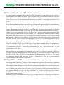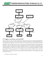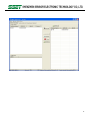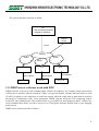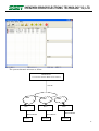
1
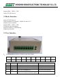
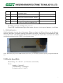
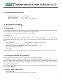
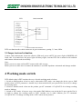
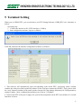
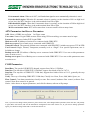
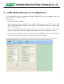
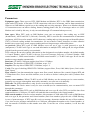
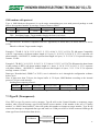
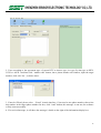
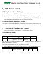
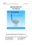
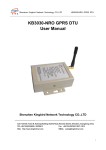
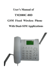
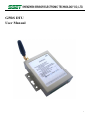
GPRS DTU
GPRS DTU
User Manual
1
GPRS DTU
1
Brief Introduction..............................................................................................................................................................3
1.1 Overview .....................................................................................................................................................................3
1.2 Features .......................................................................................................................................................................3
1.3 Safe Use.......................................................................................................................................................................4
1.4 EMI .............................................................................................................................................................................4
1.5 Appearance and Interface ............................................................................................................................................5
2
Technical Specification .....................................................................................................................................................5
2.1 GSM/GPRS: ................................................................................................................................................................5
2.2 Basic Function:............................................................................................................................................................6
2.3 User Interface ..............................................................................................................................................................6
2.4 Electric Specificity ......................................................................................................................................................7
2.5 Circumstances Specificity ...........................................................................................................................................8
3
Terminal Setting ................................................................................................................................................................8
4
Working mode switch........................................................................................................................................................9
5
Terminal Setting ..............................................................................................................................................................10
6. SMS Modem Parameter Configuration ...........................................................................................................................13
7. SMS Modem ...................................................................................................................................................................15
7.2 Type A (With protocol) ......................................................................................................................................15
7.3 Type B (Transparent).........................................................................................................................................16
8. DTU Remote Control ......................................................................................................................................................19
9. IO Control—Reading And Setting ..................................................................................................................................19
10 DTU Application Guide ..................................................................................................................................................20
11. “Plug and play” of CE-485G..........................................................................................................................................22
11.1 DTU work with DTU ...................................................................................................................................................22
11.3 DDSN server software work with DTU .......................................................................................................................25
2
GPRS DTU
1 Brief Introduction
1.1 Overview
GPRS DTU (Data Terminal Unit) is wireless data transmitting terminal of GPRS/SMS and embedded with
High reliable ARM7 CPU.
Based on the public net, GPRS DTU transmit widely, stably and reliably, GPRS DTU is widely used in
unattended operation device, Remote AMR, remote data acquisition, remote AMR, remote scheduling and
so on. Due to this product is designed for industry integrated, we adopt special designs in the temperature
scope, shaking, EMC and interface multiform and so on, to keep it good stability in the severe atmosphere,
ensure high quality for your device.
Aim at different scope user’s requirements to supply different define GPRS Terminal unit, it needs taking
industry characteristics for developing on hardware & software and system integration. GPRS mobile net
can supply TCP/IP connection; GPRS DTU can be use for internet connection, data transmitting application
and so on. GPRS DTU (Data Terminal Unit) is special GPRS wireless device that send the data from COM
port through GPRS mobile data network.
GPRS DTU is used in electric power automatic system, industry monitoring, traffic management,
atmosphere, pro-environment, pipe network monitoring, finance, securities departments and so on. Consider
the networking request from different application scope, achieve Virtual data private network in network
structure. It is applicable to small and medium data transmitting of the Center to multi-points, multi-points
scatter.
8B
1.2 Features
l Standard industrial products, EMC anti-jamming design
l Independent research, embedded 32 bit ARM7-CPU with real-time operating system.
l Embedded Watchdog chip, provide multiple Reset mechanism, can be controlled by software,
achieve industrial security mechanism perfectly.
l Working Frequency adopt 850MHz/900MHz/1800MHz/1900MHz which is suit for every country
all over the world (Including North America and South America);
l Advanced and strict data communication protocol, with the function of correction and encryption.
Never lose package when data transmission, can achieve pictures over than 100K and Flash
animation files transmission, no Mosaic happened.
l Various working mode: DTU (default), Modem, SMS Modem. DTU mode is GPRS data
transmission which can get the data from device’s COM port (RS232/RS485/TTL) and transmit to
the server in Internet. It also can receive SMS Message when DTU mode (it needs to switch IO port
to SMS when send message). SMS Modem is SMS transmission mode, user can set to type A (with
protocol) or type B (transparent). When set to Modem, compatible standard AT command
(GSM07.05 and 07.07). user can write AT command software to realize the function user need.
3
GPRS DTU
l DTU and SMS Modem can switch through User configuration software and also can change the
working modem through IO port. Set the parameter of Modem mode must after it is power-on.
l SMS Modem feature:
Ø Various networking ways: Under SMS Modem, the device with protocol (A) can network with the
device without protocol (B), the device with protocol (A) also can network with the device with
protocol (A).
Ø Under SMS Modem, can receive and send the MAX data 1024 bytes a time.
Ø Under SMS Modem, support Sending and Receiving Data form: HEX, ASCⅡ, UCS2. User is
advised to set this parameter through our configuration software before use it.
l Various networking ways, peer to peer, center to multi-points.
l Automatically IP register mechanism, can achieve various server modes, build complete super large
SCADA system.
l Remote sleep and awake: User can use appointed cell phone number to dial or send message can
sleep or awake DTU, it is convenient for user to save a lot of GPRS Flow Fee when no need to use
DTU.
l Remote modify DTU parameters: Support that SMS and data service center modify DTU
parameters.
l IO switching value function: Two channels input, two channels IO output. Remote control and
reading. Alarm status threshold, automatic alarm signal report function.
l Strong communication backup function: Support automatic switching between main server and
backup server, support TCP and UDP automatic switchover (now don’t have TCP and UDP
automatic switching function). It will connect to backup server when main server has problem, and
will take UDP to communication once TCP off line.
l Strong server software support, application for many years, strong function.
l Support special APN, data center support fixed IP and DDNS.
l Working temperature range: -40℃-80℃, communication is not effected at -40℃.
1.3 Safe Use
GPRS DTU Completely complied with national radio product safety technical regulations.
Warning:Do not touch the antenna with your hands or body. During 15 seconds after DTU started, Please
keep away from the antenna. If the antenna is damaged, you must replace it in time, assorted and qualified
cable and antenna.
1.4 EMI
Now most electric device all has electromagnetic pulse hardening, but some old device may have no, under
RF power radiation, it may go wrong. When you use GPRS DTU, please check the device nearby have
electromagnetic pulse hardening or not.
4
GPRS DTU
1.5 Appearance and Interface
GPRSS DTU has three physical interfaces:
. The first is 10 pins main interface: RS232/RS485/TTL (5V)/CMOS (3.3V), Power supply, Modem
COM port
. The second is SMA RF interface: For the antenna
. The third is embed SIM socket: For SIM card
. Size: 82mm(L)*59mm(W)*25.2mm(H)
. Weight: 170g
2 Technical Specification
2.1 GSM/GPRS:
Frequency Band: GSM850MHz/EGSM900MHz/DCS1800MHz/PCS1900MHz
GPRS Multi-slot Class 12
GPRS Mobile Station Class B
GPRS Coding: CS1~CS4
Output Power: Class 4 (2W) at GSM850MHz and GSM900MHz
Class 1 (1W) at DCS1800MHz and PCS1900MHz
Sensitivity: <-107 dBm (typ.) at GSM850 MHz <-107 dBm (typ.) at GSM900 MHz <-107 dBm (typ.) at
DCS1800MHz <-107 dBm (typ.) at PCS1900MHz
Compatible standard AT command(GSM07.05 and 07.07)
Support extend command
5
GPRS DTU
Support SMS、USSD、CSD
Embed TCP/IP Protocol
2.2 Basic Function:
Embed TCP/IP Protocol
Embed standard AT command(GSM07.05 and 07.07)
Support extend command
Support SMS、USSD、CSD
Transparent data transmitting
Support IP address or domain name
Support special APN
2.3 User Interface
1. User Interface: Interface as follow (From left to right):
1
2
3
4
5
6
7
8
9
10
VCC
GND
UTXD/A
URXD/B
Output1
Input1
UGND
Output2
Status
SW
Pin No.
Definition
Description
1
VCC
Power: DC5~24V
2
GND
Ground
3
TXD
TXD(DTU COM/RS485: A)
RS232,TTL:RXD; RS485:A
4
RXD
RXD(DTU COM/RS485: B)
RS232,TTL:TXD; RS485:B
Output1
Output NO.1 of IO; User can set it as RTS
hardware flow control port (Default: Output1)
5
For User
6
GPRS DTU
6
7
8
9
10
Input1/RST
Input No.1 of IO; User can set it as RST reset
pin (Default: Input1)
UGND
Ground (COM)
Output2
Output No.1 of IO; User can set it as CTS
hardware flow control port (Default: Output2)
Status
Online is high,offline is low
SW/Input2
Input No.2 of IO; High is DTU, low is SMS,
user can set it as Input 2 of IO(Default: SW)
RS232,TTL, RS485:Data groud
Red LED: power light, will light after power-on.
Green LED: Communications light, when connect Server is ok, it keeps on. Otherwise, it will flash.
2.SIM Card Interface
SIM Card Interface is on the side of the antenna. When you plug in the SIM card, please note the direction
and front /back side. First please push the point nearby, the drawer socket will go out automatically. Then
take out the drawer socket and put the SIM card into it, at last push the whole drawer socket(IC side of SIM
card face down) into the hole of DTU. Just as below picture:
Notes: Please don’t plug or move SIM card after power-on, if you need to plug and move, please put equipment blackouts
first.
2.4 Electric Specificity
Work Voltage: 5V~24V DC (7-60V can be custom made)
Power:
Standby: < 25mA@5V
Communicating: < 125mA@5V
Peak point current: 1.5A@5V
7
GPRS DTU
2.5 Circumstances Specificity
Working Temperature:
Storage Temperature:
Relative Humidity:
-40℃~80℃
-45℃~125℃
20%~ 95%(No Condensation)
3 Terminal Setting
3.1 Overview
GPRS MODEM must correct installation just can achieve design functions, usually equipment installation
must be approved in our company under guidance of qualified engineers.
Note: please don't power on before installing work done GPRS.
3.2 Unpack
For transportation safety, usually GPRS MODEM needs reasonable packaging, when you please keep
unpacking packaging materials used for future need transshipment. GPRS MODEM includes the following
parts:
GPRS MODEM
1Unit (Packaging depend on order quantity)
Settings software and user manual (CD-ROM)
1 copy
Small chuck antenna or club-shaped antenna (SMA interface)
1 root
5V / 2A industrial power adapter
1
data cable
1
When unpacking the case, check the specific items according to the packing of user's ordering contract.
3.3 Antennas and SIM card installed
Antenna support SMA female pedestal, spin the left from MODEM and lock it.
Insert SIM card from the antenna side of DTU, please note that SIM card metal surface outwards, make sure
insert the SIM card to drawer with stuck feeling, to avoid SIM card fall off when SIM card not insert in
place or handling equipment vibration. Remove SIM card, click the left little point of SIM card with pointed
thing, SIM seats can pop up.
Note: Please don't charged operation when connection with the antenna and install SIM card, please don’t
power-on CE-485G first.
3.4 Serial cable connection
GPRS MODEM
The cables interface type and connections as figure 3.2 show:
8
GPRS DTU
DTU
User’s termianl
3.2 Serial connection schemes
DTU user data interface cable connectors is green connectors, spacing: 3.5 mm, 10Pin.
3.5 Inspect network situation
Connect cable and antenna, insert into effective SIM card, power-onDTU, the power light of MODEM will
flash, after 10 seconds later, the power light will always light, it means DTU into a normal work condition
and connect with network successfully.
Note:
Before power-on, must confirm DTU connect with cable correct;
Before power-on, make sure to connect the antenna, to avoid RF impedance mismatch and damage module.
4 Working mode switch
DTU default value is DTU modem, the way of switch working mode as below:
1. Switch to SMS modem: it has two ways, when under DTU mode, can change the device type to SMS
modem when set DTU parameters. Another way is that switch the IO port (put the Pin 10 to low) to change
the working mode.
2. Switch to Modem mode: when run the product, put AT command: AT+QLOCPU=0 to change working
mode to Modem.
3. Switch to DTU mode: it has two ways, when under SMS Modem, can switch the IO port (put the Pin 10
to high) to change the working mode to DTU. Another way is under Modem, put AT command:
AT+QLOCPU=1 to change working mode to DTU when run the product.
9
GPRS DTU
5 Terminal Setting
When you set GPRS DTU, you are advised to use DTU Setting Software (GPRS_DTU.exe). Introduce as
follow:
Operating step:
1.Connect the interface to PC (DTU interface is COMA)
2.Run configuration software, tips are as follows:
Click OK, and enter the interface configuration software, as follows:
3. This software will automatically open corresponding serial search DTU, processing, please confirm
whether the serial port which opened by software is the serial port connected with DTU, if not, please click
the “stop” button in toolbars in the menu options from the file, then change information in COM parameters
settings window. (Note: configuration parameters are fixed by 115200bps)
4. Connect the DTU to the power supply, the system will prompt that search DTU successfully in 5 seconds
and show as below:
10
GPRS DTU
5. Click Read in toolbars, the software will read the parameters, and the display the parameter of DTU.
Local parameter:
GPRS ID: GPRS DTU the only mark, important at communication.
SIM Code: The SIM card number is only for user record.
Dis_Reconnection interval: The interval of DTU re-connects with backup server or the Main server
when DTU connection error or disconnected with Main server or backup server.
Local port: DTU local TCP or UDP port.
Heartbeat interval: The interval of server with DTU’s heartbeat for units in seconds, scope: 0-300S.
Max package: To send data packet maximum DTU data bytes (optional 512 bytes) or 1024 bytes.
Data Mininterval: The smallest interval packets (0-1000ms) serial receives data between two value is
less than this if a packet, 1~10 units for 100ms.
Recon. Interval:No Response reconnection cycle, if it do not received answer from server for some
time, DTU will reconnect with the server. The value scope: 0-3600s. If you set this parameter to Zero,
DTU will not reconnect.
Debug information: You can set DTU output its working state information or not. None: DTU will not
output working state information; Normal: DTU will not output Sample working state information;
Detail: DTU will output detailed working state information. When you connect DTU with your device,
please set this parameters value to NONE, in order to avoid output information affect users of the
equipment.
Device type: Three types as DTU, Modem, SMS. User can change this parameter to change the
working mode. DTU is for GPRS data transmission, SMS Modem is data transmission by SMS (type A
and type B), When set to Modem, through AT instructions users can achieve dialing, Internet, making
phone calls, use of messages and so on. (Note: Modem can’t switch by this way; it only can switch
through AT command when power on)
Zone: The working code DTU belongs. Generally we just use this parameter when networking.
Zone Enabled: The enabled or disabled working code which DTU belongs to.
Control Number: The phone number which control sleep or awake DTU and amend the parameters of
DTU by SMS, user can dial this number to control DTU sleep or awake, sleep mode can save a lot of
GPRS Flow Fee, DTU will be sleep or awake by any call if this value is none, so user is advised to set a
phone number.
SMS control number: This number works When DTU working as SMS Modem, it can be set three
numbers, after set the number, only these three numbers can message DTU, if no number, then any
phone number can message it.
11
GPRS DTU
IO Automatic alarm: When set it “ON”, it will send alarm signal to server automatically, otherwise, it won’t
IOA threshold (6 pin): When the IO automatic alarm is opening, set the situation of IOA as high level
or low level, the DTU interface is the sixth terminal from left to right.
IOB threshold (10 pin): When the IO automatic alarm is opening, set the situation of IOB as high level
or low level, the DTU interface is the tenth terminal from left to right
MAX reconnection times: DTU will restart when it can not connect in how many times.
APN Parameter And Server Parameter:
APN: Name of GPRS Access Point. In China: cmnet
User name: Name of login GPRS account. When using VPN networking, user name must be input.
Password: the password when DTU login GPRS.
Main server IP: IP Address of main server connected with GPRS DTU.
Main server port: Port of main server connected with GPRS DTU.
Network Protocol: The protocol of Main server connected with GPRS DTU, include two types as TCP & UDP.
User Protocol: Single, Normal, Transparent, normally set it as “Single” if no special requirement, user is
forbidden to change.
Backup server IP: IP Address of Backup server connected with GPRS DTU. User can set this parameters
same as main server’s.
Backup server port: Port of Backup server connected with GPRS DTU. User can set this parameters same
as main server.
COM Parameter:
Baud Rate: The speed of GPRS DTU adopted, support from 300 to 115200bps.
Data bits: The data bits of GPRS DTU COM data, support four kinds of bits as 5/6/7/8.
Stop bits: The stop bits of GPRS DTU COM data, support three kinds of bits as1/2/1.5, generally the stop
bits is 1bit.
Verify: The way of checking GPRS DTU COM data, Classify it to None, Even, Odd, Mark, Space, etc.
Flow Control: Com data transmission classify to none flow control, hardware flow control, software flow
control. None flow control is in general.
Notice: After choose or import parameters, and click Set button, software will prompt:
Now, if you need to change others parameter, please choose NO, after changed others parameter, then click Set, will prompt
it again, DTU will restart, and exit the Parameters configuration state after choose Yes, If you need to change parameter
again, you should to outage DTU and re-search after Power-on.
12
GPRS DTU
6.SMS Modem Parameter Configuration
You are advised to use the configuration software (GPRS_DTU.exe) to set parameters (We will
provide this software in CD with product).
Operation steps:
1. Connect the COM port with PC’s;
2. Run configuration software: GPRS_DTU.exe, software will prompt that close DTU of power, click
"OK", enter the main interface software, click “Stop” to stop searching, choose device type to SMS
Mdoem, click “Search”
Choose a COM which SMS Modem need to connect (such as COM1), then click the "search" button,
enter search state (note: when using configuration parameters are fixed 115200bps). Tip as 4.1,
3. Connect the power supply, the system will prompt that search SMS Modem successfully, Click Read
Parameters, the software will read the parameters, and display the parameter.
4. After set the parameter, click “Set” to save, click “Restart”, then power off, and power on again.
13
GPRS DTU
Parameters:
Equipment types: Three types as DTU, SMS Modem and Modem, DTU is for GPRS data transmission,
when under DTU mode, it can make TCP/IP connection with server in Internet, and for data transmission.
When set to SMS Modem, special use to the sending and receiving messages. When set to Modem, through
AT instructions users can achieve dialing, Internet, making phone calls, use of messages and so on. (Note:
Modem can’t switch by this way; it only can switch through AT command when power on)
Data types: When DTU work as SMS Modem, users can set message’s data coding way as HEX
(hexadecimal), ASCII and USC2 (Unicode). Generally, HEX is used for the communication of instrument
equipment; ASCII be used to transfer ASCII characters, sending and receiving messages with mobile phone;
USC2 is Unicode coding method for transmission, for user transfer Chinese characters or other countries
double byte or more bytes words, support sending and receiving messages with mobile phone.
ser protocol: When DTU work as SMS Modem, users can set to type A (with protocol) or type B
(transparent). CE-485G with Type A can send information to multiple DTU with type B, the target number
picked from the protocol send by user terminals;
DTU with type B can only send the information to the designated record phone number, the default number
is Control Number, when CE-485G with type B received message from one of Control Number, SMS
control number 1, SMS control number 2 and SMS control number 3, CE-485G with type B will set this
number as target number automatically.
Baud rate: CE-485G COM port support from 300 to 115200bps.
Data bits: The data bits of GPRS DTU COM data, scope: 5-9.
Stop bits: The stop bits of GPRS DTU COM data, scope:1-2.
Verify: The type of checking GPRS DTU COM data, support None, Even, Odd, Mark, Space (Can’t realize
Mark, Space)
Flow control: Com data transmission support none flow control, hardware flow control (Support RTS and
CTS hardware flow, if user need this interface, user is advise to declare it when place order), software flow
control.
Service center number: When CE-485G work as SMS Modem, use the message service center number,
generally user can get it through the network by automatic, user also can set it manually.
SIM code: The SIM card number is only for user recorded (not for communication).
Device name: The Device name is only for user recorded (not for communication), user can name DTU
through this parameters.
Control number: When DTU work as SMS Modem and set to type B, after DTU received the data from
connected device’s COM port, CE-485G will send this data as message to the Control number.
SMS control number: it can be set three numbers; this parameter is valid when DTU work as SMS Modem
and set to type B, this parameter and Control number (total: four numbers) plays the role of SMS filtering,
in case of spam messages. if DTU (type B) receive a message, determine whether this one of four numbers,
if yes, then receive messages and transfer to a COM port, and update the number as the Control number, so
that can transfer COM data to this number next time. If not the one of four numbers, it will lose this
message.
14
GPRS DTU
3B
7.SMS Modem
7.1 Overview
User is advised to set the type of DTU as SMS Modem through the configuration software. Choose the data
type of communication (HEX (default), ASCII and UCS2), then set DTU as type A (with protocol) or type
B (transparent), if set it as type A (with protocol), user send data must according to the communication
protocol provide by our company.
The synopsis of communication relationship between DTU and terminal equipment, DTU and DTU as
below form:
Type
Communication
Communication
port
interface
Work status
With protocol
Note
None
Transparent data to device
With protocol
Get target number from the package
Send message
PDU
Send to type B or mobile
Receive message
PDU
Receive any type B or mobile’s message
Send data to device
None
Transparent data to device
None
Get transparent data from device
PDU
Send message to the temp target number
Send data to device
COM port
COM Communication
A
Received data from
device/PC
Air
COM port
Air Communication
COM Communication
Received data from
device
Send message
B
Air
Get the source number from message, then
Air Communication
Receive message
PDU
detect and filter the number, if passed then
save it as temp target number.
The working principle of type A (with protocol) and type B (transparent) are as below:
7.2 Type A (With protocol)
When the device which connected with type A and need to send data to type A, then must according to the
protocol of our company to send data to type A, A will send data to target number according to protocol,
After A received data, it will check the data type with protocol: 01 means Hex, 02 means ASCII, 03 means
UCS2, if 00 means type A will convert the data to the designated data type after received data, then send the
data to type B through PDU format, type A can receive the message from any phone number, analysis the
message, convert the date to designated data type and sent it to COM port of device which connected with
type A. In this type, "Control number" and "SMS Control number" doesn't work.
With protocol
PC/Device
SMS Modem
Transparent
Type A
15
GPRS DTU
SMS modem with protocol
Type A, SMS Modem with protocol, it can be major transmitting port, user need protocol package to send
data to the appointed number by message, Protocol form as follow:
Hear (8bits)
0x7B
TPL(8bits)
Target number
(HEX)
Data length(16bits)
(ASCII)
Data(n bytes)
End(8bits)
(HEX)
0x7D
TPL:Send data format+ Target number length, the form is as below:
Send data format DATATYPE(2bit)
Target number length phoneLen(6bit)
DATATYPE:00 means Compatible with V0.1 agreement, 01 means HEX, 02 means ASCII, 03 means
UCS2;
PhoneLen: Means Target number length;
Example 1: 7B 0B 31 38 39 32 32 38 34 33 31 35 31 00 06 31 32 33 34 35 36 7D, 0B means Compatible
with V0.1 agreement, cell phone number length is 11 bytes, 31 38 39 32 32 38 34 33 31 35 31 represent cell
phone number:18922843151, 0x0006 represent data length is 6 bytes, 31 32 33 34 35 36 represent message
content: 123456.
Example 2: 7B 4B 31 38 39 32 32 38 34 33 31 35 31 00 06 31 32 33 34 35 36 7D,4B means the data format
of this package is HEX, cell phone number length is 11 bytes, 31 38 39 32 32 38 34 33 31 35 31 represent
cell phone number:18922843151, 0x0006 represent data length is 6 bytes, 31 32 33 34 35 36 represent
message content: 123456.
Data type: Hexadecimal, GSM0.7 or UCS2, user is advised to set it through the configuration software
before use it.
Note: if data more than 70 bytes, the largest buffer is 512 bytes, SMS Modem according to the internal
protocol, 70 bytes each message.
Sending data response protocol:
Head(8bits)
TPL (8bits)
Target number
Data length (16bits)
Function code(8bits)
0x7B
(HEX)
(ASCII)
(HEX)
0x01 or 0x02
End(8bits)
0x7D
Function code: 0x01 means successful sending, 0x02 means failure sending.
7.3 Type B (Transparent)
If set DTU as type B, passive receive message, Type B will set the Control Number as temporary target
number, after received message, type B will read the source number, if this number is the one of “Control
number” or “SMS Control number”, then will update this number as temporary target number, Type B will
convert the message to designated data type and send it to COM port of device which connected with type B.
when type B received the data from device,
Transparent
PC/Device
SMS Modem
Transparent
Type B
16
GPRS DTU
7.4 SMS Modem network
PC
RS232
DTU A
GSM
SMS Center
GSM
GSM
GSM
DTU B
RS232/RS485
Device
DTU B
RS232/RS485
Device
DTU B
RS232/RS485
Device
7.5 SMS Modem sending and receiving message
User can send/receive message through the provided configuration software. Proceed as follows:
1. Run SMS_Modem.Exe software, first choose the COM connected to DTU and baud rate of COM port
and so on, enter "SMS sending" page, show as follows:
17
GPRS DTU
2. Users according to the agreement type of current DTU to choose type A or type B, data type as HEX,
UCS2 or ASCII. And then click " number edit” button, into a phone number edit window, input the target
number, click edit" Set ", as below show:
3. If need to FSend, please select “Fsend” in main interface, if just send to one phone number, then select
this number in the target phone number list box, click "send" button, this message is sent out, the software
will tip sent successfully.
4. If it received message, it will show the messages’ details on the right of the information display box.
18
GPRS DTU
8.DTU Remote Control
8.1 Dialing Control Sleep and Waking Up
1.Controlled center number on DTU should set to user's cell phone number, Please refer the 5th chapter for
parameter setting details.
2.Use cell phone dial the SIM card number on DTU, if DTU is on working, DTU will break away from
GPRS and enter into sleep pattern, and user can see the green light DTU will be off. In sleep pattern, no
heartbeat and can not transmit data, no GPRS flow fee. If DTU is on sleep state, dial DTU number, it
will be waked up and connected with server, then enter into normal working state.
8.2 Internet Remote configuration Parameter
User can set the DTU parameters through our’s configuration software (the server software must be our
company’s Data Center software), but for safety's sake, user is not advised to set parameters through
Internet.
9.IO Control—Reading And Setting
User can send instruction to DTU through server, to read and control the IO flow.
9.1 IO Input state Reading
1.Read:ServerèDTU
Head
GPRS ID
Zone
FUNCTIONC
ODE
Zone enabled
PARITY
0xA881
(2bytes)
11bytes
ASCII
4bytes ASCII
0x06 (1byte)
0x00 OR 0x01
CheckSum
1byte
State: CheckSum is a accumulation data form FH to PARITY, if the data greater than 255, then choose 256
pattern, (The Remainder by divided 255)
For example: A8 81 30 30 30 30 30 30 30 30 30 30 31 30 30 30 31 06 01 02, represent that reading the
DTU’s(GPRS ID: 00000000001, Zone: 0001, Zone enabled: true.) IO status.
2.Reply: DTUèServer(or active report all this format when IO state response and change input interface)
Head
GPRS ID
0xA881
11bytes
(2bytes)
ASCII
Zone
FUNCTIONCODE
Zone enabled
IO STATE
4bytes ASCII
0x07 (1byte)
0x00 or 0x01
2bytes
PARITY
CheckSum
1byte
Notice:
1. IO Port State: High Level: ox01, Low level: ox00, in proper order is 6, 10.
19
GPRS DTU
2. When set the DTU IO automatic alarm Open, and the input terminals 6, 10 feet of DTU is to the
corresponding threshold, DTU will sent alarm information to server automatically, alarm information is
this format.
9.2 Output state of IO flow settings
1.Setting: ServerèDTU
Head
GPRS
ID
Zone
FUNCTION
CODE
Zone enabled
IO STATE
PARITY
0xA881
(2bytes)
11bytes
ASCII
4bytes
ASCII
04 (1byte)
0x00 或 0x01
2bytes
CheckSum
1byte
State: Ouput port state: high level: ox01, low level:ox00
2.Reply: DTUèServer
Head
GPRS ID
Zone
FUNCTION CODE
Zone enabled
IO STATE
PARITY
0xA881
(2bytes)
11bytes
ASCII
4bytes
ASCII
0x05 (1byte)
0x00 或 0x01
2bytes
CheckSum
1byte
State: Output port state: high level: ox01, low level: ox00
10
DTU Application Guide
10.1 Operation Steps:
(1).Plug in SIM card;
(2).Connect the antenna;
(3).Set DTU Parameters;
Connect the data cable. DTU’s user interface is 10PIN socket, If DTU is RS232 interface, you can
connect it with DB9 of COM port, if DTU is RS485 interface, and you can use one converter of
RS232-RS485 to connect it with DB9 of COM port.
Run the configuration software, choose and open all the COM port that DTU connected;
Connect with the Power. The power adaptor(5V) is One of the enclosures,first you can plug the power
adaptor into the power socket, then connect the male into the female socket of the power cable. DTU can
get power. CE-485G DTU Setting Software will list the menu of configuration. You can choose different
menu to set different parameters, such as server IP, port, baud rate and so on. (Baud rate and Verify must
be same with the device), then save the parameters and reset DTU.
(4).Connect DTU with the device
Connect DTU with the device according to the interface define of DTU. If DTU is RS232 interface, you can
connect it with the device of RS232, If the DTU is RS485 interface, you can connect it with device of RS232.
(5).Start the control center software or the SCADA software to collect the remote device’s data.
20
GPRS DTU
10.2 User utility software R&D and server planning
Users need planning on R&D software which in GPRS application, user can choose fixed IP servers or
dynamic domain mode. Based on dynamic DNS is unstable, User is not advised to adopt this way. Here
is the explain for the planning on software R&D based on fixed IP servers
Fixed IP server user can rent or hosting ISP Internet service provider, or can apply special line to our
server.
Generally speaking, user's monitoring software can divide into two modes:
One is the user monitoring software and Data center software (Data center) integration. Namely the user
monitoring software is installed on the Server, and its working mode as Server, it communicate with
and manage every scene DTU directly, the advantage of this way is communication directly, no data
transfer, Disadvantage is that the flexibility for application is not strong, server must be in the user's
master-control room (special line). So that users just can monitor and data collect in that server only.
Another is the user monitoring software and Data Center software (Data Center) separation, Data
Center dedicated to Data transfer and each machine DTU’s management, monitoring software only in
charge of the customer's business logic processing, it communicate with Data Center software through
network, and it with Data Center software is C/S architecture, the monitoring software working mode
as Client, and Data center as Server. The advantage of this way is very flexible application, user no
need special line, only need place the server in ISP service provider, and install Data center software
into server. User can manage it only by user’s monitoring software, and when monitoring software
install into a computer which connect with internet, it can achieve communication even in company or
on business trip outside. The disadvantage of this mode is data need to transfer, monitoring software is
not communicate with DTU directly, But communicate with data center software first, and then
forward data to scene DTU.
Users can plan the whole GPRS application system according to user’s request. Normally, users are
suggested using the second modem, our company's server and server software is available to offer a lot
of support when user debugging and trial in the early time. If users develop software completely, Our
company can offer SDK or Demo program when user monitoring software work as the server (when
user monitoring software and data center software is integration) or Client (when user monitoring
software and data center software is separation).
10.3 Use GPRS and SMS for communication in the same time
Generally speaking GPRS DTU with only GPRS communication function, but sometimes in GPRS data
communication, also needs SMS communication. It can use SMS as backup communications when
GPRS communication interrupt, or it can send out a warning through SMS to users mobile phone when
abnormal situation.
Receive SMS message: when under DTU mode, CE-485G can receive SMS, and send the SMS to the
user equipment through serial port, but only available for the message from message control number.
CE-485G refuses to receive the message from any other number, to avoid the interference to users’
equipment from spam messages.
Send SMS messages: when under DTU mode, it gets the data from device’s COM port and sends it to
server via GPRS, but if user needs to send data by SMS to Mobile phone or other SMS terminal, user
21
GPRS DTU
can change working mode to SMS Modem through switch Pin 10 to low. Then the data from the user
terminal can be send to Message control number or terminal by SMS.
11. “Plug and play” of CE-485G
When users don't want to or can not do software development based on customary communication to use
GPRS, then can use “plug and play”. If user can develop software, then need not to use "plug and play".
Normally, users monitoring software based on serial communication mode before user use GPRS, if user
want to use GPRS system, user is advised to change the communication mode to network communication
mode, meanwhile, Put the protocol of GPRS DTU in monitoring software (Invoke SDK from DTU
manufacturers) and building server and so on many developments and applications. My company
recommends "plug and play" solutions, user doesn't need to change its monitoring software, when users
get our product, through my company's some software support, it can achieve remote GPRS
communication through the monitoring software base on COM port communication modem. User can
build a large SCADA system with our products and software in 10 minutes. In early time user debugging
and try our products, user can use our server. If the bulk application is still need to adopt our company
server, also can lease my company server.
Our company products "plug and play" solution requires our server software (Center Data) to support, the
following various network scheme adopts our company's server software (installed in users server or our
company server).
11.1 DTU work with DTU
DTU can use with DTU. When the master control room has no condition to surf the internet, user can use a
DTU as main station, and use another DTU connected with device as slave station. This way is called plug
and play (foolish application), no need to develop any software. User can use own server, or ours. Not only
peer to peer, but also center to multi-point. This type network is very suit for the situation that main
controlled room has no condition to surf the internet or outdoor, but need remote data communication.
Connected net system structure as follow:
22
GPRS DTU
PC
RS232
DTU
Data Server
GPRS
Internet
GPRS
GPRS
GPRS
DTU
RS232/RS485
Device 1
DTU
RS232/RS485
Device 2
DTU
RS232/RS485
Device N
11.2 Appserver software work with DTU
Appserver software is the client-side communication software developed by our company and application in
one single host or multi host system, the single host or multi hosts in network are need data communications
with the equipment. Appserver software can combine to use with user's device control software (based on
COM port), it can obtain the data in user's device control software through COM part and send the data to
the DTU. In this way, when a host needs to communicate with device, Appserver software send TCP
connection request to designated server, then communication with it. At the same time, the DTU which
connected with device sends the TCP connection request to server, after connection established, CE-485G
can communicate with server, then user can use Appserver software in host communicate with every DTU
through server. This network mode is very suitable for that equipment and PC software are serial
communication mode, and need for remote data communication projects. Such as, LED display information
issue system and so on.
The Appserver interface as follow:
23
GPRS DTU
系统结构如下:
24
GPRS DTU
The system schematic structure as follow:
PC
(User monitoring software
+Appserver software)
Internet
Server
TCP/IP
Internet
GPRS
GPRS
GPRS
DTU
RS232/RS485
Device 1
DTU
RS232/RS485
Device 2
DTU
RS232/RS485
Device N
11.3 DDSN server software work with DTU
DDSN software is the server-side communication software developed by our company which can network
with the device monitor software (based on COM), it can get the monitor software data and send it to local
CE-485G. It applies in one single host or multi host system, when the single host or multi hosts in network
both need to communicate with local equipments. DDSN software accept the TCP connecting request
from DTU and communication. This network mode is very suitable for that equipment and PC software are
serial communication mode, user have own server or Through the dynamic domain name or port mapping
mode project.
DDSN server software interface as below:
25
GPRS DTU
The system schematic structure as follow:
Host server
(User monitor software+DDSN server software)
TCP/IP
GPRS
DTU
RS232/RS485
Device 1
GPRS
DTU
RS232/RS485
Device 2
GPRS
DTU
RS232/RS485
Device N
26
GPRS DTU
12. Modem
User is advised to input AT command through COM port with115200bps Baud rate in five seconds after
power up to switch work mode to Modem. AT command as below:
AT + QLOCPU = 0
After switch to Modem, CE-485G will always keep this mode. If users need to switch to DTU mode, can
change it through AT command, the AT command as below:
AT + QLOCPU = 1
Under Modem working mode, user can achieve the function through AT command; of course, user must be
familiar with AT command.
User can achieve the function according to application that dial-up, make phone call, send and receive SMS,
or GPRS transmission, and so on.
http://www.ce-transducer.com
Tel: 86 755 83766916
Floor 4; Shenzheng Building; 42 MeiLin Road; Shenzhen City; China Post code: 518049
Fax: 86 755 83763161
27