1
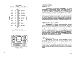
Laboratory Exercise 8
Basic Stepper Motor Control
8.1
Purpose and General Plan
The principal purposes of this exercise are the following:
• To gain familiarity with the properties of stepper motors.
• To gain familiarity with the generation of waveforms with a microcontroller, and
the use of these waveforms to control a stepper motor.
8.2
Equipment
The equipment to be used in this experiment is the same as that used in Laboratory Exercise 6. Before proceeding, make sure that your group has all of these items
available.
1. One PC running the P&E software IASM11, SIM11A, SIM11, and EVB11.
2. One Motorola M68HC11EVB evaluation board, with power supply.
3. One Motorola M68HC11EVB Evaluation Board User’s Manual.
4. One serial port cable, for connecting the evaluation board to the PC.
5. One Knight Electronics Mini-Lab 200 analog-digital lab station.
6. One stepper motor.
7. One stepper-motor control parts kit, consisting of an MC3479P stepper motor
controller chip, one 4.3 V. Zener diode, and one 47KΩ resistor,
8. Various wires for interconnection purposes.
9. One digital voltmeter.
77
78
Laboratory Exercise 8
10. One oscilloscope, with two coaxial probes..
8.3
Pre-Lab Preparation
It will be to your distinct advantage to prepare in advance for this laboratory. In addition to reading through this handout, you should do the following reading assignments.
Elementary stepper motors: Read the excerpt from the North American Phillips
Controls Corp. Stepper Motor Handbook. You may safely gloss over the formulas
concerning torque and ramping, but you should familiarize yourself with the
main ideas in the other sections.
Stepper motor control: Read Section 7.6 of the text by Kheir.
Output compare: Read the material on pages 132-134 of Kheir on output compare,
particularly Program 9. Also re-read the material in Section 8.1 of the Technical
Data manual on output compare.
Interrupt Prioritization: Read the material in 9.2.4 and 9.2.5 of the Technical Data
manual, which covers this topic. This material is also summarized on pages 104105 of Kheir.
In addition, you should attempt the following.
Software: Implement the software described in Section 5.1 of this document, using
either SIM11A or SIM11 as a development platform,
8.4
Procedure – Part 1: Stepper Motor Configuration
The stepper motor to be used in this experiment is a two-phase bipolar unit from
Jameco Electronics. The documentation for this motor is reproduced in Figure 1. The
Motorola MC3479P stepper-motor driver chip will also be used as a smart interface
to the motor, eliminating the need to generate the raw stepping signals within the
microcontroller software. The procedure which is to be followed in this part of the
exercise is given below, in a series of ten steps.
1. Familiarize yourself with the prototyping area. The prototyping area of the minilab consists of two beige platforms with wiring holes, into which wires and pins of chips
may be inserted. They are situated in the center of the mini-lab, and are attached with
velcro. They are not connected electrically to the mini-lab in any way. Pull one off
and replace it, in order to convince yourself of this.
Basic Stepper Motor Control
Figure 8.1: Stepper motor documentation.
79
80
Laboratory Exercise 8
Each platform consists of a 14 (row) × 63 (column) array of holes. At the outside of
each platform are two rows of 63 holes each, labelled A and B. All of the holes in each
such row are connected to each other. However, elements in different rows (even when
those rows are labelled by the same letter) are not connected. On the inside of the
strips are two groups of five rows each. One group of rows is labelled a through e, and
the other f through j. In each group, each set of five holes within a given column are
connected to each other. Thus, for each column, elements a through e are connected to
each other, and elements f through j are connected to each other. However, elements
e and f are not connected. Elements in distinct columns of these inner rows are not
connected.
Use the voltmeter and a pair of wires to test the connectivity of a platform, making
sure that you understand these conventions.
2. Wire the circuit shown in Figure 2. Figure 2 shows the connections which are to be
made to the MC3479P chip. This circuit corresponds fairly closely to that shown on
Figure 8.2: Wiring configuration for the stepper-motor driver.
the documentation of Figure 1. The major difference is that the four dual-transistor
“H” servo driver circuits connected to the stepper motor in Figure 1 have been omitted.
Rather, the leads of the stepper motor are connected directly to the driver chip. The
purpose of these circuits is to increase the power available to drive the motor. For the
level of power required in this experiment, the chip itself can supply sufficient power,
and so the simpler configuration is adequate. For a real servo application, however,
Basic Stepper Motor Control
81
one would almost certainly include such amplifier circuits.
Before you begin wiring, make sure that your mini-lab is shut off and unplugged.
Never wire a live circuit!! While the voltage levels involved in this experiment are
not dangerous, it is very easy to destroy sensitive components with incorrect wiring,
even if the connection is made only for an instant.
Begin by installing the chip into the prototyping area, Install the chip so that one row
of pins is in row e of the prototyping platform, and the other in row f. The holes in
the prototyping platform are spaced correctly for such dual in-line integrated-circuit
packages.
The pins on the chip are numbered 1 through 16, going counterclockwise from the
upper left. The top of the chip is identified by a special mark, which is usually a small
notch in the case of the chip. This notch is depicted by a semicircle on the illustration
of Figure 2.
The wiring will be done with sections of solid wire, stripped at each end. There should
be plenty available, but if not, a spool of wire and cutters will be provided. The
notations in capital letters (e.g., GND, GEN, POS, and PULSER) refer to connectors on the
mini-lab.
It is a good idea to tie all of the GND connections together on the prototyping platform,
and then to run a single wire to a GND connector on the mini-lab.
Pins 9 and 10 should be connected to separate pulser switches. Each should be connected to the strip of the pulser labelled 1, so that the untoggled logic level supplied
is one.
The band on the Zener diode identifies the cathode; i.e., the end with the zig-zag line
pointed to by the triangle. (The left end of the diode in Figure 2.) Make sure that
you have installed it correctly; if you reverse the connection and apply power, it is
possible that the integrated circuit will be destroyed by the reverse voltage from the
motor coils. The resistor is of course symmetric; it may be installed either way.
Pin 11 is provides a special output signal which will not be used, and may be left
unconnected.
3. Disconnect the power lead Disconnect the lead connecting pin 16 to the POS connector of the mini-lab. Disconnect the end at POS, leaving the end which is connected
to the prototyping platform and the integrated circuit connected. This ensures that,
when the mini-lab is energized, no power will be delivered to the prototyping area.
4. Set POS to 9 V. Connect the common end of a digital multimeter to the GND connection of the mini-lab, and connect the voltage lead to POS. (You may need to use
some ingenuity to make a good connection. Consult your laboratory instructor if you
need help.) Set the multimeter to read voltage. After ensuring that you have performed step 3 above correctly, plug in and energize the mini-lab. Adjust the leftmost
82
Laboratory Exercise 8
potentiometer at the bottom of the lab (it is labelled for the range from 0 to +18) until
the voltmeter reads approximately 9 volts. This value is not critical, but it should not
be high by more than a volt or so. The higher it is, the more current the entire circuit
must support, and so the hotter it will run.
5. Shut down, and reconnect the power lead. Switch the mini-lab off, and reconnect
the power lead to the prototyping area.
6. Have the laboratory instructor check your circuit. Before proceeding, have the laboratory instructor check you wiring.
7. Configure for square waves. Set the multiplier knob in the upper left to 100, set the
ADJUST knob to 1 (fully counterclockwise), and set the waveform knob just below it to
square wave (fully counterclockwise).
7. Verify operation of the stepper motor. Turn on the power to the mini-lab. Slowly
turn the the ADJUST knob clockwise; the motor should begin to turn and increase in
speed as adjust is turned. If the motor does not turn, switch off the power immediately
and check your wiring.
Notice that, as the frequency increases, so does motor speed, However, there is a
maximum frequency, beyond which the motor will first start to stutter, and finally,
with a slight further increase, stop. At this point, internal friction and moment of
inertia within the motor prevent faster rotation.
Toggle the PULSER switch which is connected to pin 10, and note that the motor reverses
direction.
Toggle the PULSER switch which is connected to pin 9, and notice that the motor
doubles in speed.
8. Connect the oscilloscope. To analyze more systematically the relationship between
input frequency and motor speed, it is necessary to measure both. We will use an
oscilloscope to observe and to measure the input signal. While it is possible to measure
the speed of the motor shaft with the appropriate sensors, we will use a much cruder
measure of simply counting the number of revolutions over a given period of time.
Turn off the mini-lab, and connect an oscilloscope to measure the frequency of the
signal at GEN. Use channel 1 for the signal display. You will find the triggering to be
more stable if you use a separate trigger lead, and set the scope for external trigger.
The red trigger lead should also be connected to GEN. Both black leads on the scope
probes should be connected to GND.
Turn the power for the mini-lab back on, and observe the waveform on the screen.
There are several models of oscilloscopes, each with its own peculiarities. If
you have trouble getting the scope to work, ask your laboratory instructor
for assistance.
Basic Stepper Motor Control
83
9. Determine the relationship between frequency and speed. The relationship between
input signal frequency and motor shaft speed should be linear. In this part of the experiment, you will verify the extent to which this is the case. You are to complete,
experimentally, (a copy of) the table to the left in Figure 3, and then compute the
values for the table to the right. In addition, prepare a plot of signal frequency vs.
motor speed, for both half-step and full-step operation.
Recorded Data
Signal
Motor Speed
Period Half-step
Full-step
(msec.) Rev. Sec. Rev. Sec.
1
2
5
10
15
20
Signal
Period
(msec.)
1
2
5
10
15
20
Computed Data
Signal
Motor Speed
Freq.
(rpm)
(KHz.) Half-step Full-step
Figure 8.3: Prototype data tables for the frequency-speed relationship.
10. Determine the critical frequencies. In addition to the above measurements, determine the maximum input frequency which may be applied with the motor running
smoothly. At a sufficiently high frequency, the motor will be unable to keep up with
the signal, and will start to vibrate and miss steps. Record both this frequency and
the unit number of the motor, which is written on the casing. (Because of mechanical
differences, this critical frequency will be different for different motors, even of the
same manufacturer and model. Usually, the specifications will give a minimum such
frequency.)
8.5
8.5.1
Procedure – Part 2: Using the EVB to Control
a Stepper Motor
Development of the Software
Before you arrive at the laboratory, you should write and test the program for this
assignment, using SIM11A and/or SIM11. At this point in the course, you should
have acquired a reasonable amount of competence in programming microcontroller
applications on the 68HC11. Therefore, this section will provide somewhat less detail
on how to implement the program than have previous laboratory exercise descriptions.
84
Laboratory Exercise 8
Make sure that you think through your software design, and that you have covered the
usual routine tasks.
The primary function of the software for this assignment is to generate a square
wave, which will be used to drive the MC3479 chip, which will in turn drive the stepper
motor. The timer output compare unit of the processor, which was used in Laboratory
Exercise 7 to implement the delay, will be used in this exercise as well. It is possible
to enable an output compare unit so that whenever an interrupt occurs for that unit,
the logic level of a pin on the processor is toggled. If the interrupts occur at regular
intervals, the output will thus be a square wave!
To permit easy adjustment of the frequency of the wave, a coefficient which represents a multiple of the wavelength will be read from Port C. When a new value is read
and latched at this port, the speed of the motor will change.
A high-level description of the algorithm for this exercise is shown in Figure 4.
Set Output Compare as a higher priority interrupt than Port C;
Enable interrupts for Port C;
Enable interrupts for Output Compare 2;
Initialize Wavelength_coefficient;
Start first half-cycle of the output wave;
While true do
Nothing; ;; Wait for interrupts!!
End while;
When interrupt for Port C
Read new Wavelength_coefficient from Port C;
End when;
When interrupt for Output Compare 2
Toggle the wave output line;
Initiate a new half cycle;
End when;
Figure 8.4: High-level representation for the program.
The first five lines of the main program are initialization commands; we will return
to those shortly. For now, look at the body of the program, which consists of a
single while loop which does nothing but wait for an interrupt! The entire program
is interrupt-driven. Whenever a timer interrupt occurs, the level of the output wave
is toggled, and whenever a Port C interrupt occurs, a new frequency for the wave is
computed and used.
The interrupt handler for Port C should be familiar by now. This handout will
not provide any information on how to implement it, because you have already done
it in Laboratory Exercise 7. All you need do is to port the appropriate code from that
exercise to this one. Remember that this imported code must include specification of
Basic Stepper Motor Control
85
the interrupt vector and jump table, as well as initial enabling of interrupts.
In this exercise, Timer Output Compare 2 will be used. Actually, any of the five
timer output compare lines could be used for either this or the previous exercise. We
use a different line than that used in Laboratory Exercise 7 for the sake of variety. The
first step in configuring for use of this interrupt is to declare the interrupt vector and
jump table entry. Consult Table 9-2 of the Technical Data manual, and the Interrupt
Vector Jump Table (Table 3-1 or 3-2, depending upon the version of the manual) of
the EVB user’s manual for the correct addresses to use.
The next step is to initialize properly for interrupt handling. A skeleton specification
is provided in Figure 5. First of all, as in Laboratory Exercise, we want the timer
;;**********************************************************************
;; <set the OC2F bit of register TFLG1>; Enable output compare 2.
;; <set the OL2 bit of register TCTL1> ;;Configure timer output-compare 2.
;;**********************************************************************
;; <Enable interrupts on OC2> ;; Similar to OC1 case of previous lab.
;;**********************************************************************
Figure 8.5: Initialization for Output Compare 2.
to generate an interrupt whenever its value matches that of the appropriate output
compare register. In this case, it is register TOC2 which will be used, so we must set the
OC2F bit of register TFLG1. Consult 8.1.11 of the Technical Data manual for details,
including the location of the OC2F bit. Next, it is necessary to configure the Output
Compare 2 unit so that its output pin (which is pin PA6)1 is toggled each time that a
successful compare occurs (between the timer value and the value in register TOC2).
Upon consulting 8.1.9 of the Technical Data manual, it is seen that bit OL2 of register
TCTL1 is to be set, and the rest of the bits are to be cleared. (Verify that this is correct.)
Now let us look at realization of the interrupt-service routine. A skeleton is shown
in Figure 6. It is important to understand that the output pin PA6 is toggled each time
that the contents of register TOC2 matches the timer value. It is not necessary to service
the interrupt for this to happen. However, interrupt service is necessary in order to set
the timer output compare register to the appropriate new value for the next interrupt.
This function is performed by a subroutine named Do half cycle, which is sketched in
Figure 7. The key idea is that the Wavelength coefficient, which is the value read
in from Port C, contains the eight most significant bits of the 16-bit value which is the
number of clock cycles between toggles of the output line. Thus, if Half cycle = 10,
1
This provides a convenient means of observing the “square wave” generated by a program run
on SIM11A or SIM11. Just configure the simulator to display the value of Port A, which is at location
1000h. Bit 6 (second from the left) should toggle between 0 and 1 as the program runs. Of course,
the frequency of the simulator will be much less than that of the real processor. Expect a slowdown
on the order of 103 .
86
Laboratory Exercise 8
;;**********************************************************************
;;**********************************************************************
;; Service TOC2 interrupt.
Svc_TOC2_int:
;;
<Exit if no OC2 interrupt occurred>;; Check OC2F bit of TFLG1.
bsr
Do_half_cycle
;;
<Clear the OC2F bit of TFLG1>;;
Use bset!!!
rti
;;**********************************************************************
Figure 8.6: Routine to service the TOC2 interrupt.
;;**********************************************************************
;; Subroutine which configures the timer for one-half cycle.
Do_half_cycle:
;;
<Half_cycle := Wavelength_coefficient * 256>
;;
<TOC2 := TCNT + Half_cycle>
rts
;;**********************************************************************
Figure 8.7: Routine to initiate a half-cycle.
there will be 10 × 256 × 0.5µsec = 1.28msec per half cycle, and so the frequency of the
wave will be 1/(2 × 1.28msec/cycle) = 391Hz.
Notice that Do half cycle must be invoked once at the beginning of the program,
as well as each time that a timer interrupt occurs.
To loop endlessly waiting for interrupts, the appropriate instruction to use is a
branch to the current address, as shown in Figure 8, It is not appropriate to use the
;;**********************************************************************
bra
$
;;**********************************************************************
Figure 8.8: An endless loop which waits for interrupts.
wai command, because once an interrupt is processed, the instruction after the wai
will be processed. With the bra $, execution will return to the branch instruction
upon completion of interrupt service.
There is one subtle point which we have not discussed. In this program, unlike
that of Laboratory Exercise 7, two different interrupts are enabled at the same time.
Thus, it is possible, for example, that a Timer Output Compare 2 interrupt will occur
while an interrupt for Port C is being serviced. The question thus arises as to what
Basic Stepper Motor Control
87
happens in such a situation. Is the interrupt for Port C processed to completion before
the interrupt for Timer Output Compare 2 is serviced, or is processing of the Port C
interrupt temporarily suspended in favor of the interrupt for Timer Output Compare
2? The answer is that there is a priority list for interrupts, and those with a lower
listing will be suspended in favor of those with a higher listing, should a conflict occur.
Sections 9.2.4 and 9.2.5, and particularly Table 9-6, of the Technical Data manual,
provide detailed information. Table 5.1 of Kheir provides the same information. As a
power-up and reset default, the entry labelled Reserved (Default to IRQ) is given top
priority. The pecking order then proceeds down to the bottom of the table and then
back to the top and down to the entry just before the one of highest priority. The
lowest priority interrupt is thus SCI Serial System.
This priority system may be altered by modifying the rightmost four bits (the right
nibble) of register HPRIO. To make a given interrupt source that of highest priority,
one places the bit pattern found in Table 9-6 of the Technical Data manual for that
interrupt into the register. Shown in Figure 9 is the code necessary to make Timer
Output Compare 2 the interrupt of highest priority. The appropriate bit pattern for
;;**********************************************************************
HPRIO
equ $103C ;; Highest priority I interrupt register.
HPRIO_clear equ $03
;; Priority bits to clear,
HPRIO_set
equ $0C
;; Priority bits to set.
;;**********************************************************************
ldx #HPRIO
bset 0,X,HPRIO_set
;; Set interrupt priority pattern
bclr 0,X,HPRIO_clear ;; Timer output compare is highest.
;;**********************************************************************
Figure 8.9: Making TOC2 the interrupt of highest priority.
the right nibble of HPRIO is 1100. Because the leftmost nibble contains settings which
need not concern us, it is best to leave those bits alone. The code thus sets and clears
only the bits in the right nibble. Make sure that you understand how it works.
It is important to understand that this setting may be changed only when global
interrupts are masked (i.e., the I bit of CCR is set). Typically, priorities are only altered
in this fashion in the initialization phase of a program, before interrupts are enabled.
In the program for this exercise, it is desirable in principle to have the timer interrupt have a higher priority than the Port C interrupt. It is clearly undesirable
for processing of data from Port C to delay proper generation of the square wave.
However, since transition of the output pin occurs upon output compare match, and
not upon processing of the interrupt, the wave will be generated properly provided
that the timer interrupt can be serviced before the next transition of the output
wave must be generated. Even with Wavelength coefficient = 1, this time will
88
Laboratory Exercise 8
be 256 × 0.5µsec = 128µsec, which is loads of time for the microprocessor. Since the
data to Port C are latched via a toggle switch, it is impossible to generate more than a
few interrupts per second, due to mechanical limitations of the switch, so there will be
plenty of time to process all interrupts. Nonetheless, to simulate a situation in which
Port C could be pounded relentlessly with new data, you should install the prioritization code given above into your program, and you should definitely understand what
it is doing.
8.5.2
Hardware Wiring and Experiments
Once the software has been developed and tested on the simulator, it is time to connect
the EVB to the stepper motor circuit, and let the microcontroller control the motor.
Here is the procedure to follow.
1. Connect PA6: Begin by disconnecting the lead from GEN to pin 7 of the MC3479,
and connect pin 7 to pin PA6 of the EVB. Also connect the ground pin of the EVB to
GND of the mini-lab. This will enable you to use the EVB, rather than the mini-lab, as
the source of the driving square wave to the stepper.
2. Connect Port C to the mini-lab Connect the eight pins of Port C to the eight switchable output lines of the mini-lab. just as you did in previous experiments.
3. Reconnect the oscilloscope: Connect both the channel 1 input and the trigger input
of the oscilloscope to pin 7 of the MC3479, and set the scope to trigger externally. This
will allow the waveform generated by the microcontroller to be displayed on the scope.
4. Test the circuit: Run the program, and observe the waveform and motor speed. If
all is well, the motor should run, with lower values at Port C corresponding to faster
speeds. Note that very low settings (typically three or less) may result in frequencies
which will stall or stutter motor operation.
5. Frequency measurement: For several switch settings for Port C input, measure the
frequency by observing the pattern on the oscilloscope. Draw up tables of the form
shown in Figure 10, and compute the appropriate values. Plot both of the computed
values from the second table as a function of the Port C input value, and comment on
how well they agree. Note that since measurement of motor speed is not an issue here,
quite accurate readings may be obtained.
For low values at Port C, the motor may stutter or lock. To avoid damaging it, you
should disconnect the power connection to pin 16 of the MC3479 when making those
measurements.
Basic Stepper Motor Control
Recorded Data
Port C Signal
Input Period
Value (msec.)
1
2
4
8
16
32
64
128
89
Computed Data
Port C Signal Freq.
Signal Freq.
Input
from
from Measured
Value Port C Value Signal Period
(msec.)
(KHz.)
(KHz.)
1
2
4
8
16
32
64
128
Figure 8.10: Prototype data tables for the Port C to frequency relationship.
8.6
Submission Requirements
Submission of this assignment requires two components, a written submission and
a demonstration. The exercise is not considered to have been submitted until both
components are completed.
Written submission: Your written submission must consist of a program source listing (.asm file) and an assembler listing (.lst file) for a final program embodying
all concepts identified in 5.1 above. The code of your program should be clear
and well documented. Clarity is far more important than cleverness.
You will not gain points for saving a few microseconds or a few bytes,
but you will lose points if your code is difficult to follow.
In addition to the program, you must submit a short write-up which includes
the data for the tables, the plots, and the answers for the questions associated
with items 9 and 10 of Section 4, as well as for item 5 of Section 5.1. Make sure
that your write-up includes the number of the stepper motor which you used.
In addition, you should provide general observations and conclusions.
Since you should retain your copy of this laboratory handout for study purposes,
it is best to use a copy of the tables of Figures 3 and 10, rather than the pages
from this document.
Demonstration: The laboratory instructor will evaluate the operation of your programs by running them. He will let you know how this is to be done; by an
in-person demo, or by submitting a diskette.