1
Terminal Connections
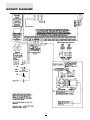
Auxiliary Input Terminal “AUX IN” (also KEY ARMING)
The “AUX IN” input terminal is a normally open 24 hour zone.
It can be programmed from the keypad to be silent or
audible. There is no display on the keypad for the “AUX IN”
input. An alarm on this input is created by applying a positive
voltage or by closing a contact between the “AUX IN”
terminal and the positive auxiliary supply. See “Programming
Guide [Q] [8]” sections [09] and [10] for programming the
alarm and restoral codes.
The “AUX IN” terminal can also be used as a momentary key
arming/disarming input. See “Programming Guide” section
[28] for a list of options for the “AUX IN” terminal.
Note: The keyswitch arming feature must be
implemented using a UL listed device.
“AC” Power Terminals
Use a 16.5 VAC transformer with a minimum 40 VA rating to
supply AC power to the PC3000. The transformer should not
be connected to an outlet that is controlled by a switch. If AC
failure occurs it is displayed as a trouble on the keypad (see
“Keypad Functions [Q][2] Trouble Conditions”). It can also
be transmitted to the monitoring station as a trouble
condition (see “Programming Guide [Q][8]” sections [09]
and [10] for alarm and restore codes and section [22] for AC
transmission delay).
Auxiliary Power Terminals “AUX” and “GND”
The auxiliary power supply can be used to power motion
detectors and other devices requiring 11 VDC. 400 mA 11
VDC is available from the “AUX” (positive) and “GND”
(negative) terminals when the PC3000 is used with one
keypad. For each additional keypad the auxiliary supply
rating must be reduced by 60 mA. The auxiliary supply is
fused with the keypad supply at 1 amp. Auxiliary fuse failure
transmission can be sent (see [Q][8] sections [09] and [10]).
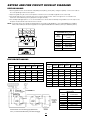
”FIRE” Zone Input
The “FIRE” zone is a supervised (normally open alarm
initiating contact) end-of-line resistor circuit designed to
accept “Latching” four-wire smoke detectors.
(See “Fire Circuit Installation Diagram”.)
On alarm, (fire zone shorted) the bell output will pulse the
signal to indicate that the fire zone has been activated. Alarm
memory and transmission by the digital communicator is
delayed 30 seconds. If the alarm is acknowledged, by
pressing the [#] key before the 30 second delay has expired
the signals will silence and the transmission will be aborted.
If the alarm is not acknowledged and the 30 second delay
expires, the fire memory latches and the transmission cannot
be aborted.
If the smoke detector is not restored to normal after the
signal has silenced, the signal will resound after 90 seconds.
And 30 seconds after that, the communicator will transmit. If
the signals resound, they may again be silenced, [#] key,
and the communicator will be aborted if silence occurs within
the 30 second delay period.
To restore the smoke detector to normal, clear all products
of combustion from the detector and reset the detector by
pressing [Q] and then holding down [4] for 2 or 3 seconds.
This action will remove power from the smoke detector and if
it is clear of smoke, the detector will return to normal. If the
detector is still in alarm, the signals will sound immediately
and the above sequence will repeat.
For an open on the FIRE zone, the keypad sounder will beep
twice every 10 seconds and the “Trouble” light will show on
the keypad. The communicator will transmit the trouble
condition if programmed for trouble transmission. The
audible “Trouble” signal may be silenced by pressing the [#]
key. To determine the nature of the trouble, press [Q][2]. (see
the “Trouble Display” section.)
Switched Auxiliary Power Terminals
“SW AUX” and “GND”
The switched auxiliary supply can be switched off
momentarily from the keypad (see “Keypad Commands
[Q][4]”). The “SW AUX” terminal is positive and the “GND”
terminal negative. The 400 mA auxiliary supply rating must be
reduced by any current taken from the switched auxiliary
supply. The switched supply shares the same fuse as the
auxiliary supply.
Bell/Siren Terminals “BELL [+]” and “BELL [-]”
These terminals are for powering bells or other devices
requiring a steady output voltage on alarm. The bell output is
fused for 5 amps. When connecting sirens (speakers with
siren driver already built-in), be sure to observe the correct
polarity. Connect the positive lead to the “BELL [+]” terminal
and the negative lead to the “BELL [-]” terminal.
If no siren or bell is used, connect a 1000 ohm resistor
between “BELL [+]” to “BELL [-]”. The bell/siren alarm output
is pulsed (1 second on 1 second off) when an alarm is
created by the [F] keypad zone, by the FIRE zone, or when
the Bell Pulse option is enabled in section [19] light 1.
Note: During each LINKS2000 transmission the bell will
be turned off for approximately 1 second.
Keypad Terminals “RED”, “BLK”, “YEL” and “GRN”
Connect the four coloured wires from the keypads to these
terminals. When connecting more than one keypad, connect
in parallel across the keypad terminals at the control panel
(i.e. all reds wires together, all blacks together, all yellows
together and all greens together). The keypad red and black
power supply terminals are fused through the auxiliary fuse.
Zone Input Terminals “Z1” to “Z16”
Zone inputs “Z1” to “Z16” are supervised end of line (E.O.L.)
resistor circuits. Each input must be terminated with a 1K
ohm E.O.L. resistor. An alarm condition will be created if a
normally open contact is used to short across the E.O.L.
resistor. An alarm is also created if normally closed contacts,
wired in series with the E.O.L. resistor, are opened. See the
wiring diagram for normally open and normally closed
contact connection. The type of circuit or zone definition
Programmable Output Terminal “PGM OUT”
Connect the PC3000 PGM OUT terminal to the “PGM”
terminal on the LINKS2000. When the LINKS2000 unit is
used with the PC3000, the PGM output may not be used for
any function other than the LINKS2000.
5