1
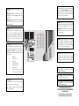
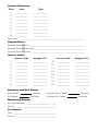
System Reference
Zone
Area
Type
1
___________
_____________
2
___________
_____________
3
___________
_____________
4
___________
_____________
5
___________
_____________
6
___________
_____________
7
___________
_____________
8
___________
_____________
Fire Zone: ___________________________________________________________
Keypad Zones
Keypad Zone [F] Fire _________________________________________________
Keypad Zone [A] Auxiliary _____________________________________________
Keypad Zone [P] Panic _______________________________________________
Access Codes
Access Code
Assigned To...
9
___________
_____________
_____________
10
___________
_____________
_____________
11
___________
_____________
___________
_____________
12
___________
_____________
5
___________
_____________
13
___________
_____________
6
___________
_____________
14
___________
_____________
___________
_____________
___________
_____________
Access Code
Assigned To...
1
___________
_____________
2
___________
3
___________
4
7
___________
_____________
15
8
___________
_____________
16
Entrance and Exit Delays
Entry Delay:
Exit Delay:
seconds
seconds
Auxiliary Entry Delay:
Auxiliary Exit Delay:
Monitoring Station
Account Number: __________________________
Phone: ____________________________________
For Service
Call: ______________________________________
Phone: ____________________________________
seconds
seconds
A Word About Your System
The PC3000 Security System has been designed to give you the greatest possible
flexibility and convenience. Read this manual carefully and become familiar with
the operation of your Security System. Your installer will tell you which commands
listed in this manual apply to your system. Fill out the System Reference sheet in this
manual and store it in a safe place for future reference. The label provided for the
inside of the keypad door can be used to record which sensors are on each zone.
Important Note
Remember that no security system can prevent emergencies. It is only intended to
alert you in case of an emergency and should not take the place of prudent security
practices or life and property insurance.
It is important to test your system every week. To do this, first inform the monitoring
station that you are testing your system. Then, with the system disarmed, activate
all detection sensors one at a time and observe the zone light come on at the keypad
as each sensor is activated. Perform a bell test by entering [ ],[6],[Master
Code],[8] with the system disarmed. The PC3000 can be programmed at the time
of installation to automatically perform a test transmission to the monitoring station
on a regular basis. If the system has not been programmed for this automatic test,
call the monitoring station for instructions on how to perform a test transmission.
Don’t forget to inform the monitoring station when you have finished your test.
*
Check to see if the “Trouble” light is on when arming the system. See the Trouble
Display section in this manual for a description of the different trouble conditions.
Contact your installer for assistance if the trouble condition cannot be located and
corrected.
How Your System Works
Your PC3000 Security System is made up of a control panel, one or more PC3000RK
keypads, and various detectors and sensors. The control panel will be mounted out
of the way in a utility room or basement. The metal cabinet contains the system
electronics, fuses and stand-by battery. There is normally no reason for anyone but
the installer to have access to the control panel. The keypad(s) have an audible
indicator, display lights and command entry keys. The keypad is used to send
commands to the system and to display the current system status. Keypads are
mounted in convenient areas close to the exit-entry doors. The security system has
up to eight zones or areas of protection. Each zone used will have connected to it
various sensors, such as door or window contacts, motion detectors, glassbreak
detectors and vibration or shock sensors. When a sensor is in alarm, a keypad light
will be on to indicate which zone is in alarm.
Master Code
The 4 digit Master Code is used for arming and disarming the system, for
programming additional access codes, and for changing other features. The
Master Code will be supplied to you by your installer. All keypad entries are made
by pressing one key at a time and may be changed by you at any time if the installer
selects an option. For additional access codes, see Programming Additional
Access Codes.
Arming
Close all protected doors and windows and stop movement in areas covered by
motion detectors. If the “Bypass” light is ON, be sure zones are being intentionally
bypassed before arming the system (see Zone Bypassing).
Check to see that the “Ready” light is ON (all zones are closed). The system cannot
be armed unless the “Ready” light is ON. Enter a [4 digit access code]. As each
digit is entered, the keypad sounder will beep. Once the correct access code is
entered, the “Armed” light will come ON and the keypad sounder will beep quickly.
If the access code was entered incorrectly or the “Ready” light was not ON, the
keypad sounder will beep steadily for 2 seconds.
When the correct code is entered and the system is armed, exit through the door
indicated by your installer as the exit-entry door. The exit time may be changed by
your installer (please refer to the Quick-Arm feature).
Auto-Bypass Option - Home-Away Arming
This feature, if selected by your installer, will allow you to arm your system with any
valid access code and the system will automatically bypass the interior zones if
those interior zones have been designated as home-away zones by the installer.
When activated, the “Bypass” light will come ON. If you exit within the allowed exit
time, the system will automatically reactivate the interior zones. This feature is
designed to save the user from having to manually bypass interior zones each time
they wish to arm the system and remain at home.
In residential applications where the system has been armed and the interior zones
are automatically bypassed, the interior zones can be reactivated from a keypad
outside the interior zones protection area (e.g. a bedroom). To reactivate the interior
zones, press [ ] then [1] and the “Bypass” light will go out.
*
Entry Delay Off Arming
If you wish to arm your system and eliminate the entry delay, enter [ ],[9] before
your access code. The “Armed” light will flash as a reminder that the system is
armed and has no entry delay. An entry through any zone programmed as a delay
zone will create an instant alarm.
*
Disarming
Enter the premises only through the door indicated by your installer as the entry
door. The keypad sounder will be ON. Go to the keypad and enter the [4 digit
access code]. If an error is made entering the code, press the [#] key and enter the
code again. The “Armed” light will go out and the keypad sounder will stop. The
correct access code must be entered before the allowed entry time expires. The
entry delay time may be changed by the installer.
If an alarm occurred while the panel was armed, the “Memory” light and the light for
the zone which caused the alarm will start to flash and will continue flashing for 2
minutes. At the end of 2 minutes, the keypad lights will stop flashing and the keypad
will return to the normal Ready condition.
If you return home and find an alarm has occurred while you were away, it is possible
that an intruder may still be on the premises. Go to a neighbour’s and if your system
is monitored, call the monitoring station. They will advise what action has been
taken as a result of the alarm and whether the premises are safe to enter. If your
system is not monitored, call the local police to investigate.
Alarm Memory Display
If the “Memory” light is on, an alarm has occurred since the last time the panel was
armed. The alarm memory will automatically be displayed when the system is
disarmed (see Disarming).
*
Press the [ ] then [3] keys to display which zone caused the alarm.
The alarm memory will be cleared when the panel is re-armed.
Press [#] to return to Ready.
Zone Bypassing
Bypassed zones do not cause an alarm. Use zone bypassing when access is
needed to part of the protected area. Also, damaged wiring or contacts on a zone
may be temporarily bypassed until repairs can be made so that the panel can be
armed.
*
To bypass zones, enter [ ],[1] and the zone numbers to be bypassed. i.e. [0][1]
for zone 1, [1][6] for zone 16. If the [0] key is pressed twice instead of a zone number,
all zone bypasses will be removed. If the [9] key is pressed twice, the last group
of zones which was bypassed will be recalled. Press [#] to return to Ready.
For security reasons, your installer may prevent the bypass command from
operating on certain zones.
The “Bypass” light is ON as long as at least one zone is bypassed. Do not
unintentionally bypass zones when arming. Zone bypasses are automatically
cancelled each time the panel is disarmed and must be re-applied before the next
arming.
Trouble Display
The PC3000 continuously monitors a number of possible trouble conditions. If one
of these conditions occurs, the keypad sounder will beep quickly twice every 10
seconds and the keypad “Trouble” indicator will light. Pressing any key on the
keypad will silence the beeper but the “Trouble” light will remain on until the trouble
condition is cleared. If you cannot determine the cause of the trouble condition, call
your installer for assistance. Press the [ ] then [2] keys to display the type of
trouble. The zone lights indicate the type of trouble condition.
*
Zone Light
Trouble
1
Defective Stand-by Battery
2
AC Power Failure (see NOTE below)
3
Day Zone Trouble
4
Telephone Line Problem
5
Unsuccessful Communication Attempt with
Monitoring Station
6
Bell Circuit Failure
7
Smoke Detector Circuit Trouble
8
Loss of Time on System Clock
Press [#] to return to Ready.
NOTE: The keypad buzzer will not sound for AC failure until there is also a low
battery condition. The “Trouble” light will come ON as soon as AC fails and will
remain on until AC restores.
Smoke Detector and Fire Alarm Reset
If your system is equipped with smoke detectors or other fire alarm detectors, use
the following instructions for resetting an alarm. Before resetting a fire alarm signal,
be sure you know the source of the alarm and that there is no danger (see
Evacuation Planning elsewhere in this manual).
The system bell/siren alarm signal pulses 2 seconds ON and 2 seconds OFF when
the alarm is generated from the fire circuit. The transmission to the monitoring
station is delayed by 30 seconds. The alarm may be silenced and the transmission
delayed for 2 minutes by pressing any number key on the keypad. If the detector
causing the alarm is reset before the 2 minute delay expires, no further alarm will
occur. If the detector is not reset, at the end of the delay the alarm will start again
and the transmission will occur in 30 seconds if a keypad key is not pressed.
An immediate fire alarm signal and transmission is generated by holding down the
[1] and [3] keys at the same time for 2 seconds.
Some smoke detectors require entering a keypad command to reset them after an
alarm. Press [ ] then hold down the [4] key for several seconds. If the smoke has
cleared, the smoke detector will reset and the fire zone light will go out when the [4]
key is released. If the smoke has not cleared from the detector, open a window or
door and fan clean air into the detector and try resetting again.
*
Ready light ON: system is ready to be
armed.
Ready light OFF: open zone. Zone
must be closed or bypassed before
arming.
Ready light flashing with “Armed” light
ON indicates access code 9-16
programming.
Bypass light comes ON when you
bypass a zone. To bypass a zone,
press [ ], [1], [Master Code] and
then the zone(s) you wish to Bypass.
Enter 01 for zone 1; 08 for zone 8; 16
for zone 16. Press [#] to return to
ready.
*
Trouble light ON means there is a fault
on the system. Press any key to silence
keypad beeping. Press [ ] then [2] to
display trouble type; one or more zone
lights will come ON to indicate the type
of trouble.
When ON in the normal operating
mode, the Zone Lights indicate an
open zone. eg. open door, window,
etc. Refer to zone chart on keypad
door for zone information.
Armed light will come ON indicating
system is armed. Ensure “Ready” light
is ON, enter [4 digit] access code.
Armed light flashing with “Ready”
light indicates access code 9-16
programming.
Memory light ON means an alarm
has occurred. To display zone that
caused alarm, press [ ] then [3].
Zone light will come on indicating
which zone caused the alarm.
*
*
1
2
3
4
5
6
7
8
Battery
A.C. Power
Day loop
Telephone line
Communicator
Bell circuit
Smoke detector circuit
Clock needs resetting
Fire light is ON when a detector on the
fire loop is in alarm. Press any key
within 30 seconds of first alarm to get
2 minutes to reset smoke detectors.
Press [F] for 2 seconds to activate
FIRE transmission.
Press [A] for 2 seconds to activate an
AUXILIARY transmission.
Press [#]...
...when an error is made in entering
code, then enter code again.
...to return to ready state after using
[ ] commands.
*
Press [P] for 2 seconds to activate
PANIC transmission.
THESE BUTTONS WILL NOT
FUNCTION UNLESS PROGRAMMED
BY INSTALLER.
Colored labels on keypad door
indicate which keys are active.
Programming Access Codes
Up to 15 access codes in addition to the Master Code can be entered from the
keypad.
*
Press [ ], [5] and [Master Code]. The “Program” light will flash and the zone lights
will show which codes have already been programmed. To enter a new code or
change an existing code, first press the code number [0][1] to [1][6] and then enter
your [4 digit] code. To erase a code, press [
] instead of a [4 digit] code.
Note that the [ ] and [#] keys cannot be used in a code.
****
*
Press [#] to return to Ready.
Quick-Arm Feature
When the Quick-Arm feature is enabled, the panel may be armed simply by entering
[ ], [0] instead of a 4 digit code. The [ ], [0] command will not disarm the panel.
*
*
*
Enter [ ], [6], [Master Code], [4] to turn ON and OFF the Quick-Arm feature. When
the command is entered, the keypad will beep 3 times if the feature is being enabled
and will sound one long beep if the feature is being disabled.
Press [#] to return to Ready.
Door Chime Feature
The door chime feature is used, while the panel is disarmed, to provide a tone from
the keypad each time a door or window is opened or closed. The doors and
windows which will provide this indication are programmed by your installer.
*
Enter [ ], [6], [Master Code], [6] to turn the door chime feature ON and OFF. When
the command is entered, the keypad will beep 3 times if the feature is being enabled
and will sound one long beep if the feature is being disabled.
Press [#] to return to Ready.
Alarm Test
Enter [ ], [6], [Master Code], [8] for a 2 second test of the keypad lights, keypad
sounder and alarm bells.
*
Press [#] to return to Ready.
Keypad Zones
There are three zones which can be activated from the keypad. They are activated
by pressing two keys at the same time and holding them for 2 seconds. These zones
may or may not be active on your keypads depending on how your installer has
programmed them.
[F]
Keypad FIRE zone. Pressing this key for 2 seconds will activate the
keypad fire zone and the bell/siren output will pulse ON and OFF. This
zone is annunciated by the “Fire” light on the keypad.
[A]
Keypad AUXILIARY zone. Pressing this key for 2 seconds will produce
a series of beeps on the keypad along with the transmission. To
confirm transmission, the keypad sounder will beep 6 times.
[P]
Keypad PANIC zone. Depending on how your installer programs the
panel, pressing this key for 2 seconds may produce a completely
silent alarm or an audible alarm along with the transmission. If
programmed as audible, the alarm bell will ring.
Testing
It is recommended that the system be tested on a weekly basis. NOTE: Perform
tests in the off-peak hours, such as early morning or late evening.
1 Inform the monitoring station that you are testing your system.
2 Disarm the system (“Ready” light should be ON).
*
3 Perform a battery/bell test by pressing [ ], [6], [Master Code], [8]. The alarm
will sound for about 2 seconds. If a trouble occurs after the test, press [ ], [2]
to view the trouble condition.
*
4 Activate each sensor in turn. For example, open a door or window. Observe the
zone light come ON as each sensor is activated. The zone light will go OFF as
each sensor is restored to normal (door or window is closed).
5 Press the [F] key. The signal will sound in a pulsed mode. Arm then disable the
panel to silence the signal. Repeat this test by pressing the [A] and [P] keys in
turn. Remember, the [A] key does not ring the bell and the [P] key may not be
programmed for an audible signal.
6 If the fire zone is used, activation will cause the signal to sound in a pulsed mode.
CAUTION: Do not use open flame or burning materials to test a smoke
detector. Contact your installer for information on safe methods to activate a
smoke detector.
7 Should your system fail to operate properly, call your installer for service.
8 When testing is complete, call and advise the monitoring station.
Maintenance
With normal use, the system requires minimum maintenance. The following should
be observed:
1 Do not wash the keypad with a wet cloth. Light dusting with a barely damp cloth
should remove normal accumulations of dust.
2 The battery/bell test is designed to determine battery condition, however it is
recommended that the stand-by battery be replaced every three years.
3 For other system devices such as smoke detectors, passive infrared, ultrasonic
or microwave motion detectors or glassbreak detectors, consult the respective
manufacturer’s literature for testing and maintenance.
Fire Safety in the Home
Most fires occur in the home and to minimize this danger it is recommended that
a household fire safety audit be conducted and a family escape plan be
developed.
Household Fire Safety Audit
1 Are all electrical appliances and outlets in a safe condition? Check for frayed
cords, over-loaded lighting circuits, etc. If you are uncertain about the
condition of your electrical appliances or household service, have a professional
evaluation.
2 Are all flammable liquids stored safely in closed containers in a well ventilated
cool area? Cleaning with flammable liquids should be avoided.
3 Are fire hazardous materials (such as matches) well out of reach of children?
4 Are furnaces and wood burning appliances properly installed, clean and in
good working order? Have a professional evaluation.
Family Escape Planning
There is often very little time between the detection of a fire and the time it becomes
deadly. It is thus very important that a family escape plan be developed and
rehearsed.
1 Every family member should participate in developing the escape plan.
2 Study the possible escape routes from each location within the house and
since many fires occur at night, special attention should be given to the escape
routes from sleeping quarters.
3 It is essential that escape from a bedroom be possible without opening the
interior door. Consider the following when making your escape plans:
• Make sure that doors and windows that open to the outside are easily opened.
Ensure that they are are not painted shut, and that their locks operate
smoothly.
• If opening the exit or using the exit is too difficult for children, the elderly or
handicapped, plans for rescue should be developed. This includes making
sure that those who are to perform the rescue can promptly hear the fire
warning signal.
• If the exit is above the ground level, an approved fire ladder or rope should
be provided as well as training in its use.
• Exits on the ground level should be kept clear. Be sure to remove snow from
exterior patio doors in winter; outdoor furniture or equipment should not block
exits.
• The family should have a predetermined assembly point where everyone can
be accounted for; for example, across the street or at a neighbour’s house.
• Once everyone is out of the house, call the Fire Department.
• A good plan emphasizes quick escape. Do not investigate first or attempt to
fight the fire, and do not attempt to rescue belongings or pets as this takes up
valuable time. Once outside, do not re-enter the house. Wait for the fire
department.
• Write the plan down and rehearse frequently, so that should an emergency
arise, everyone will know what they are to do. Revise the plan as conditions
change; for example, when there are more or fewer family members in the
home, or if there are changes to the house.
• Make sure your fire warning system is operational by conducting weekly tests
as noted elsewhere in this manual. If you are unsure about system operation,
contact your installing dealer.
• It is recommended that you contact your local fire department and request
further information on home fire safety and escape planning. If available,
have your local fire prevention officer conduct an in-house fire safety inspection.
Limited Warranty
Digital Security Controls Ltd. warrants that for a period of twelve months from the
date of purchase, the product shall be free from defects in materials and workmanship
under normal use and that in fulfilment of any breech of such warranty, Digital
Security Controls Ltd. shall, at its option, repair or replace the defective equipment
upon return of the equipment to its repair depot. This warranty applies only to
defects in parts and workmanship and not to damage incurred in shipping or
handling, or damage due to causes beyond the control of Digital Security Controls
Ltd., such as lightning, excessive voltage, mechanical shock, water damage, or
damage arising out of abuse, alteration or improper application of the equipment.
The foregoing warranty shall apply only to the original buyer, and is and shall be in
lieu of any and all other warranties, whether expressed or implied and of all other
obligations or liabilities on the part of Digital Security Controls Ltd. Digital Security
Controls Ltd. neither assumes, nor authorizes any other person purporting to act on
its behalf to modify or to change this warranty, nor to assume for it any other warranty
or liability concerning this product.
Warning
Digital Security Controls Ltd. recommends that the entire system be completely
tested on a regular basis. However, despite frequent testing, and due to but not
limited to, criminal tampering or electrical disruption, it is possible for this product
to fail to perform as expected.
Printed in Canada
© 1994 Digital Security Controls Ltd.
29000664 R1
October 7 1994
INSTRUCTION
MANUAL
PC3OOO
WITH PC3OOORK KEYPAD
Department of Communications Notice
NOTICE: The Canadian Department of Communications label identifies certified equipment. This certification
means that the equipment meets certain telecommunications network protective, operational and safety
requirements. The Department does not guarantee the equipment will operate to the user's satisfaction.
Before installing this equipment, users should ensure that it is permissible to be connected to the facilities of
the local telecommunications company. The equipment must also be installed using an acceptable method
of connection. In some cases, the company's inside wiring associated with a single line individual service may
be extended by means of certified connector assembly (telephone extension cord). The customer should be
aware that compliance with the above conditions may not prevent degradation of service in some situations.
Repairs to certified equipment should be made by an authorized Canadian maintenance facility designated
by the supplier. Any repairs or alterations made by the user to this equipment, or equipment malfunctions,
may give the telecommunications company cause to request the user to disconnect the equipment.
User should ensure for their own protection that the electrical ground connections of the power utility,
telephone lines and internal metallic water pipe system, if present, are connected together. This precaution
may be particularly important in rural areas.
CAUTION: Users should not attempt to make such connections themselves, but should contact the
appropriate electric inspection authority, or electrician, as appropriate.
The Load Number (LN) assigned to each terminal device denotes the percentage of the total load to be
connected to a telephone loop which is used by the device, to prevent overloading. The termination on a loop
may consist of any combination of devices subject only to the requirement that the total of the Load Numbers
of all the devices does not exceed 100.
The Load Number of this unit is 42.
AVIS: L’étiquette du ministère des Communications du Canada identifie le matériel homologué. Cette
étiquette certifie que le matériel est conforme à certaines normes de protection, d’exploitation et de sécurité
des réseaux de télécommunications. Le Ministère n’assure toutefois pas que le matériel fonctionnera à la
satisfaction de l’utilisateur.
Avant d’installer ce matériel, l’utilisateur doit s’assurer qu’il est permis de le raccorder aux installations de
l’entreprise locale de télécommunication. Le matériel doit également être installé en suivant une méthode
acceptée de raccordement. Dans certains cas, les fils intérieurs de l’entreprise utilisés pour un service
individuel à ligne unique peuvent être prolongés au moyen d’un dispositif homologué de raccordement
(cordon prolongateur téléphonique interne). L’abonné ne doit pas oublier qu’il est possible que la conformité
aux conditions énoncées ci-dessus n’empèche pas la dégradation du service dans certaines situations.
Actuellement, les entreprises de télécommunications ne permettent pas que l’on raccorde leur matériel à des
jacks d’abonné, sauf dans les cas précis prévus par les tarrifs particuliers de ces entreprises.
Les réparations de matériel homologué doivent être effectuées par un centre d’entretien canadien autorisé
désigné par le fournisseur. La compagnie de télécommunications peut demander à l’utilisateur de débrancher
un appareil à la suite de réparations ou de modifications effectuées par l’utilisateur ou à cause de mauvais
fonctionnement.
Pour sa propre protection, l’utilisateur doit s’assurer que tous les fils de mise à la terre de la source d’énergie
électrique, des lignes téléphoniques et des canalisations d’eau métalliques, s’il y en a, sont raccordés
ensemble. Cette précaution est particulièrement importante dans les régions rurales.
AVERTISSEMENT: L’utilisateur ne doit pas tenter de faire ces raccordements lui-même; il doit avoir recours
à un service d’inspection des installations électriques, ou à un électricien, selon le cas.
L’indice de charge (IC) assigné à chaque dispositif terminal indique, pour éviter toute surcharge, le
pourcentage de la charge totale qui peut être raccordée à un circuit téléphonique bouclé utilisé par ce
dispositif. La terminaison du circuit bouclé peut être constituée de n’importe quelle combinaison de
dispositifs, pourvu que la somme des indices de charge de l’ensemble des dispositifs ne dépasse pas 100.
L’Indice de charge de ce produit est 42.