1
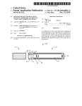
Vilnius Aerosol Generator (VAG) User’s Manual Setup, Operation and Maintenance CH TECHNOLOGIES (USA), Inc. © Copyright 2015 CONTENTS 1. Description and Principle of Operation………………………….……………..…. 2. VAG Specifications…………..…………………………………………………… 3. VAG Operation Procedures…………………………………………….…………. 3.1. Preparing the VAG for Operation………………….………………..………. 3.1.1. Assembling the Aerosol Monitor……………………………………... 3.1.2. Assembling the VAG Parts……………………………………….……. 3.1.2.1. Without Sharp Cut Cyclone…………………………………..…. 3.1.2.2. With Sharp Cut Cyclone…………………………………..…….. 3.1.3. Setting Up WinDust Pro Software..……………….…………….……. 3.2. Operating the VAG…………………..……………….……………..………. 3.2.1. Loading the VAG with Powder………………………………………... 3.2.2. Setting Up the Aerosol Monitor for Operation………………………... 3.2.3. Controlling Powder Output during VAG Operation………………….. 3.2.4. Monitoring with MicroDust Pro during VAG Operation……………… 3.2.4.1. Monitoring with the Control Unit……………………………..…. 3.2.4.2. Monitoring with WinDust Pro Sowftare…………………..…….. 3.2.5. Analysis of Aerosol Concentration Data on WinDust Pro.…………… 3.3. Correction Factor (Calibration) of Dust Monitor…..………………….……. 3.3.1. Calibration Procedures with External Gravimetric Sampling………… 3.3.1.1. Gravimetric Sample Data Analysis.…………………………..…. 3.3.2. Calibration Procedures without External Gravimetric Sampling……… 3.3.3. Working with a User-defined Calibration Factor……………………... 4. Cleaning and Maintenance Procedures……………………………………………. 4.1. Quick Cleaning…………………………………….………………..………. 4.2. Deep Cleaning……………………………………………………………….. 4.3. Re-Assembly of the Deagglomerator……………………………………….. 5. Disclaimer……………………...………………………………………………….. 6. Limited Warranty……………………………………..………….…………….….. Page 2 of 32 3 7 8 8 8 9 9 12 13 14 14 14 17 18 18 18 19 20 20 22 22 23 25 25 26 27 30 31 Page 3 of 32 1. DESCRIPTION AND PRINCIPLE OF OPERATION The Vilnius Aerosol Generator (VAG) is a general-purpose dry powder disperser. The VAG is a highly reliable device, which produces aerosol concentrations from 1 to 2,500 mg/m3. In addition to its capability of producing high aerosol concentrations, VAG provides exceptional de-agglomeration characteristics. The instrument consists of Controller and Disperser units (Figure 1). The Disperser contains a dynamic aerosolization and a de-agglomeration assembly. The aerosolization assembly includes a dust chamber for placement of a powder to be aerosolized. Airflow, directed into the chamber through a control valve and jets impinges upon the powder dispersing it into the air. Simultaneously air jets activate a turbine which is used for continuous supply of powder under the air jets. The aerosolization efficiency is increased by means of a vibrating cam which oscillates the turbine. Figure 1. View of VAG Units The aerosolization assembly is interconnected with the de-agglomeration assembly by a capillary. The lower end of the capillary is positioned at the top of the dust chamber, while the upper end of the capillary enters the region of high velocity airflow. The aerosol particles are de-agglomerated in the de-agglomeration assembly by the shear forces that are generated between the high velocity airflow, exiting through a narrow gap around capillary, and the low velocity aerosol stream exiting the capillary (Figure 2). Page 4 of 32 Figure 2. View of the De-agglomerator Assembly A portable aerosol monitor (Casella MicroDust Pro), equipped with an in-line Clean lens Adaptor, is used for continuous monitoring of the aerosol output (Figure 3). The electrical signal from the Casella sensor is used as Controller feed-back signal. If the aerosol output decreases, the Controller causes the turbine to vibrate more actively and increases the air flow rate through the jets. On the contrary, the turbine is slowed down and air flow rate is decreased when aerosol output increases. An illustration of the VAG’s operation principle is given in Figure 4. Figure 3. View of Casella MicroDust Pro Aerosol Monitor with Clean Lens Adaptor Page 5 of 32 Figure 4. Schematic of VAG’s Principle of Operation Page 6 of 32 The highest stability of aerosol output is achieved when Casella aerosol monitor is employed for monitoring of aerosol output. Other types of real-time aerosol monitors also can be used to monitor aerosol output. However, additional modifications of the electrical circuit must be made for that purpose. Furthermore, the stability of aerosol output may be less condensed and aerosol concentration range reduced if other than the Casella aerosol monitor is used. For applications that require particle size control of the aerosolized dry powder, the VAG is equipped with a standard 5 m sharp cut cyclone. Custom sharp cut cyclones for other cut sizes are also available. The VAG is designed to operate continuously for 0.5 to 6.0 hours depending on the desired aerosol concentration. Page 7 of 32 2. VAG SPECIFICATIONS Concentration Range: 0-160 g/m3 Air Flow Rate: 8-12 L/min Dry Powder Capacity: ~ 2 gr Dispensing Time: up to 6 hours Power Input: 110/220 VAC, 50/60 Hz Page 8 of 32 3. VAG OPERATION PROCEDURES 3.1. Preparing the VAG for Operation When you receive your VAG, you should unpack it carefully and check to make certain that the following parts are all present and in undamaged condition: Controller De-agglomeration unit Cable connecting Controller to De-agglomeration unit Cable connecting Controller to MicroDust Pro Casella MicroDust Pro complete kit which includes: - MicroDust Pro Monitor - Clean Lens Adaptor - Calibration kit - Software - Power supply unit - Data cable 5 mm sharp cut cyclone (if you ordered the VAG model equipped with cyclone) Straight slip-joint connector Elbow slip-joint connector (if you ordered the VAG model equipped with cyclone) Your VAG may vary slightly in appearance depending upon the model that you ordered and fittings you requested, if different from the standard ones. An overview of all parts and accessories of the VAG assembly is given in Appendix 1. Any changes from the standard pieces listed above will be noted on your shipping memo. PLEASE KEEP YOUR SHIPPING MEMO FOR FUTURE REFERENCE. If you find that anything has been damaged in transit, contact the carrier of the shipment immediately in addition to CH Technologies 3.1.1. Assembling the Aerosol Monitor 1. Remove the inlet and outlet compression fittings from the CLA body (black block). The inlet fitting is the one connected to the cyclone; the outlet fitting is connected to in-line diluter under the inhalation tower. 2. Remove the Inlet and Outlet laminar flow cuvette parts from the CLA body 3. Slide the protection collar of the aerosol detection cell all the way down 4. Apply a thin layer of silicon grease on the O-rings of the CLA block Page 9 of 32 5. Slide the probe shaft into the hole of the CLA body and rotate it until the measurement chamber is perfectly aligned with the inlet and outlet of the CLA 6. Take the Inlet piece (make sure you check the label “INLET” engraved in it) and insert it on the side of the CLA block marked INLET 7. Connect the inlet compression fitting and tighten it by hand. 8. Insert the Outlet piece (make sure the label “OUTLET” in engraved on it) into the side of the CLA block marked OUTLET and screw in the remaining compression fitting. 3.1.2. Assembling the VAG Parts 3.1.2.1. Without Sharp Cut Cyclone 1. Assemble the provided straight stainless steel slip-joint connector on deagglomerator’s outlet and tighten the nut by hand 2. If your VAG comes with a sharp cut cyclone, use the same procedure to assemble the elbow slip-joint connector on the de-agglomerator 3. Slip the inlet compression fitting of the assembled CLA (see Section 3.1.1.) into the slip-joint connector and tighten the nut by hand 4. Insert the provided VAG’s outlet connector into the outlet compression fitting of the CLA and tighten the nut. 5. Connect your compressed air line (1/4” OD) to the air inlet of the VAG 6. Using the provided control cable, connect the “DISPERSER” port on the control unit with the “CONTROLLER” port on the de-aggregation unit (see Figures 5 and 6 for illustration of connectors). 7. Next, use the provided 2.5 mm stereo jack cable to connect the control unit of the MicroDust pro monitor to the port on the VAG control unit labeled “CEL-712” (Figure 5). This connection will provide the VAG control unit an analog output signal proportional to the aerosol concentration measured by the aerosol monitor 8. Use the provided Mini B USB to A USB cable to connect the aerosol monitor to a USB port on a PC (Figure 7) Page 10 of 32 9. Last, connect the VAG outlet to your application, i.e. inhalation exposure chamber, using appropriate connectors Figure 5. Rear Panel of the VAG Control Unit Figure 6. Rear Panel of the VAG De-aggregator Page 11 of 32 Figure 7. Connections on the MicroDust Pro Control Unit When completed, the assembly of the VAG without sharp cut cyclone should look similar to Figure 8: Figure 8. VAG Assembly without Sharp Cut Cyclone Page 12 of 32 3.1.2.2. With Sharp Cut Cyclone 1. Assemble the provided elbow stainless steel slip-joint connector on deagglomerator’s outlet and tighten the nut by hand 2. Thread the cyclone inlet to the slip-joint connector and tighten the nut by hand. Make sure that the body of the cyclone is vertical and its outlet is straight up. 3. Slip the inlet compression fitting of the assembled CLA into the cyclone outlet and tighten the nut by hand 4. Insert the provided VAG’s outlet connector into the outlet compression fitting of the CLA and tighten the nut 5. Follow steps 5 thru 8 of Section 3.1.2.1. to complete VAG setup When completed, the assembly of the VAG with sharp cut cyclone should look similar to Figure 9: Figure 9. VAG Assembly with Sharp Cut Cyclone Page 13 of 32 ! ATTENTION! It is recommended the use of a ring stand to securely hold the MicroDust Pro in place during operation 3.1.3. Setting Up WinDust Pro Software The Microdust Pro comes with a proprietary data acquisition and analysis software called WinDust Pro. There are two ways to record the measurement data: they can be stored in the control unit of the probe for later download or can be logged in directly onto a PC through WinDust Pro. Average, spot, maximum and minimum aerosol concentration values are recorded over the logging period. The software package offers a variety of statistical and visual tools for data analysis. The data file can also be opened onto Excel or other spreadsheet software for further processing and visualization 1. Install the WindDust Pro software on your computer using the provided installation package 2. Following procedures outlined in Section 4.1.2.1., connect the MicroDust Pro control unit to the computer 3. Turn ON the MicroDust Pro control unit 4. Double click on the WinDust Pro icon on the computer desktop to launch the program 5. The profile of the MicroDust Pro supplied with the system has already been stored in WinDust Pro but, if you would like to change it or add another profile, click on menu Edit > Profiles 6. In the dialogue window that appears, click on Edit… if you would like to change the existing profile or New… if you would like to add a new one 7. In the Properties dialogue window that appears next, click on Data Files tab > Browse… to select the folder where you would like to store the data files 8. Click on Communications tab and under Port: select from the drop-down list the USB port the device is connected to. If you are unsure about the port, go to Device Manager from Windows Control Panel, click on Ports (COM & LPT) and check on what COM port does “Prolific USB-to-Serial Comm Port” appear. Click OK after finish editing the device profile. 9. Click button Accept to finish setting up the software Page 14 of 32 3.2. Operating the VAG 3.2.1. Loading the VAG with Powder 1. Unscrew two butterfly screws on Disperser and open the dust chamber 2. Place powder on the top of turbine as in Figure 10 ! ATTENTION! The volume of the loaded powder must not exceed 2/3rd of the chamber’s volume 3. Close the chamber and tighten the butterfly screws by hand, making sure that the seal on the chamber is air tight Figure 10. Loading the VAG with Powder 3.2.2. Setting Up the Aerosol Monitor for Operation In order for the VAG to work correctly, the appropriate measurement range, display averaging time, logging interval and I/O signal output range must be selected on the MicroDust Pro. Follow these steps to set up the aerosol monitor for work with the VAG: 1. Turn on the MicroDust Pro control unit and wait until Last Measurement screen appears Page 15 of 32 2. Press Menu key 3. On the next screen, select the Settings icon advance to the next screen 4. Select the Setup icon Settings screen (Figure 11) and press Run/Stop key to and press Run/Stop key to go to Measurement Figure 11. Measurement Settings Screen on MicroDust Pro 5. Using the Up and Down keys on the control unit, navigate to menu Range. Once menu Range is highlighted, press Run/Stop key to activate it. 6. With the menu Range activated, press repeatedly Left or Right keys to select the appropriate measurement range. The available measurement ranges are: 0-2.5 mg/m3 0-25 mg/m3 0-250 mg/m3 0-2500 mg/m3 0-25 g/m3 0-250 g/m3 Page 16 of 32 The measurement range should be selected such that the maximum expected measured concentrations fall well within the upper limit of the range. For example, if the target VAG concentrations are between 1,000-1,500 mg/m3, the range 0-2,500 mg/m3 should be selected. 7. When the desired measurement range has been chosen, press Save key to select it ! ATTENTION! DO NOT select Auto range. The VAG will not function properly if you do! ATTENTION! Operation at high dust concentrations might lead to contamination of probe optics and a failure to operate on the lowest measurement ranges. Contaminated ranges will become locked out, however normal operation may be available on other ranges. ! 8. Next, in the Measurement Settings screen navigate to Display Averaging menu and highlight it by pressing the Run/Stop key 9. Use the Left or Right keys to choose the desired Display Averaging interval and press Save key to select it. The available intervals are between 1-60 seconds but it is strongly recommended to select between 1-5 seconds since it provides for faster control feedback loop. 10. Navigate to Logging Interval menu and highlight it. Available intervals range from 1 second to 60 minutes. 11. Choose the desired interval value using Left or Right keys and press Save key to select it 12. Last, to set up the I/O signal output range, press Exit key to go back to the previous screen 13. Navigate to Alarm & I/O Setup icon and press Run/Stop key to activate it 14. On the Alarm & I/O Setup screen, navigate to the Analog Output FSD menu and press Run/Stop key to highlight it 15. Using Left or Right keys, choose the appropriate range and press Save key to select it. Page 17 of 32 ! ATTENTION! Select for the Analog Output FSD the same range as the Measurement Range. Otherwise the VAG will not work properly! 16. Press the Exit key consecutively until you get to the Data screen 3.2.3. Controlling Powder Output during VAG Operation The VAG uses the feedback of the aerosol monitor to control the aerosol output at desired concentration levels. The output is controlled by adjusting the Control dial of the VAG. 1. Turn on VAG Controller 2. If you haven’t set up the MicroDust Pro, follow instructions in Section 3.2.2. to do so 3. Pressurize the air supply line of the VAG and, using appropriate flow controllers, set the air flow rate at between 8-12 L/min 4. Start operating the generator with the Control dial all the way to the left (zero output) 5. Turn the dial clockwise and adjust the position to a predetermined relative units (voltage) value. As soon as the output is adjusted, the red LED light labeled “Valve” turns on indicating that the air valve has opened starting the powder generation. The concentration measured by the aerosol monitor will quickly rise until it reaches the concentration that corresponds to the relative unit number selected by the Control dial. Once the equilibrium is reached, the VAG will operate with short bursts of air (quick opening and closing of the air valve) to maintain a constant output. During this time the red “Valve” LED will appear blinking in rapid succession. 6. To change VAG’s output during operation, adjust the Control dial clockwise to increase it and vice-versa 7. Dust generation will continue until all the test article in the cup is consumed. A rapid decrease of the measured concentration by the MicroDust Pro indicates that the material has been exhausted and the generator needs refilling. 8. To stop VAG operation, first turn the output Control dial all the way to the left, turn off compressed air supply and last, power the VAG down Page 18 of 32 3.2.4. Monitoring with MicroDust Pro during VAG Operation Before starting measurements with the Microdust Pro, a zero-span check of the calibration status of the probe should be performed. The span calibration check is performed using the calibration insert supplied by the factory. For step by step calibration check procedures and guidelines on recalibration refer to the Casella Microdust Pro User’s Manual supplied with the monitor. Enter the results of the calibration check onto the Aerosol Monitor Data Collection Sheet. ATTENTION! Positive readings during a Zero Check indicate that the monitor’s detector lens is contaminated. Re-zero the probe to zero. If zero cannot be reached it means that the lens is dirty and he probe should be sent to the factory for cleaning and re-calibration. ! If you haven’t done yet so, follow procedures outlined in Section 3.1.2. and 3.2.2 to connect the control unit of the MicroDust Pro to the computer and set up the operational monitoring parameters now. 3.2.4.1. Monitoring with the Control Unit 1. Turn the control unit ON and wait until wait until Last Measurement screen appears 2. Press View key to access the Data screen. The instrument will display instantaneous values of measured concentrations. 3. Press View key again to display a graphical representation of the aerosol concentrations measured over the last 3 minutes. Note that the scale of the chart corresponds to the measurement range selected 4. Pressing View key once more will take you back to the Last Measurement screen 5. Press Run/Stop key to start logging in measured aerosol concentrations 6. To end data logging, press Run/Stop key again and in the Stop Run? Screes that appears press Yes key to terminate the data recording session 3.2.4.2. Monitoring with WinDust Pro Software 1. Turn the control unit ON 2. Make sure you have entered the right correction factor for the dust you are using. For procedures how to calibrate the monitor for a particular dust and how to use a calibration factor, refer to Section 3.3. Page 19 of 32 3. Launch WinDust Pro software 4. Click on menu Comms > Real Time or click button to start monitoring. On the Realtime Data window that appears you can see a time chart of the aerosol concentration as measured by the monitor. 5. Click on Auto Scale button to automatically fit the measured values in the chart 6. Click on drop-down lists Timebase, Averaging and Log interval to select data recording parameters 7. Click on Start logging button to begin recording and storing aerosol concentration data 8. When the monitoring session is up, stop recording the data by clicking on button Stop logging 9. Click on button Close to finish real-time monitoring with WinDust Pro 3.2.5. Analysis of Aerosol Concentration Data on WinDust Pro 1. If the data file is already stored on the PC, open the file by selecting Open… under menu File. 2. If not, first download the data files from the internal datalogger of the control unit by selecting Download… under menu Comms. 3. After the file is loaded, you can: a) Examine the raw data. Click on button b) Display a summary report. Click on button View c) Plot the data. Click on button or select Table from menu View or select Summary from menu or select Graph from menu View 4. Windust pro data files (.dat) are saved as comma delimited ASCII text and can also be opened and processed using standard spreadsheet application such as Excel Page 20 of 32 3.3. Correction Factor (Calibration) of Dust Monitor Light scattering instruments exhibit some sensitivity to a particulate’s refractive index, size, shape and color. When faced with varying dust types, the sensitivity of the instrument will differ slightly due to variations in particulate size, refractive index and color. The MicroDust Pro’s use of a narrow forward scattering angle minimizes these effects but for optimum calibration to a specific dust type, gravimetric calibration is required. The monitor is factorycalibrated with ISO Fine 12103-1 A2 (equivalent to Arizona Road Dust). For accurate concentration readings of any other particulate, the default calibration factor (=1) has to be adjusted. This is done in one of two ways: 1) by sampling in parallel from the inhalation chamber with the MicroDust Pro and the gravimetric sampler and then comparing the T.W.A of the instrument’s readings with the mass concentration determined by the filter, and 2) by aerosolizing in totality a known amount of powder and comparing it with instruments T.W.A. readings. 3.3.1. Calibration Procedures with External Gravimetric Sampling 1. Load the VAG with test article as outlined in Section 3.2.1. 2. Connect the provided calibration adaptor to the VAG outlet (purchased separately) or your own adaptor 3. Weigh a 47 mm filter pad and load it in the gravimetric sampler (purchased separately) 4. Connect the filter holder to the sampling port of the calibration adaptor 5. Connect a sampling line with a known sampling flow rate to the outlet of the filter holder. The sampling assembly should look similar to the one in Figure 12. 6. Turn ON the MicroDust Pro control unit 7. Set up Logging Interval per procedures in Section 3.2.2. 8. Following procedures outlined in Section 3.2.3., start aerosol generation. Wait until the aerosol monitor indicates that the output has reached stability. 9. Access the Data screen Page 21 of 32 Figure 12. Setup for Calibration with External Gravimetric Sampling 10. In quick succession, turn on the sampling line of the gravimetric sampler and press Run/Stop key on the MicroDust Pro control unit to start logging in concentration readings 11. At the end of the pre-determined sampling period (usually 10-15 minutes), turn off the sampling line and, in quick succession, press Run/Stop key and Yes key on the next screen to stop logging 12. Turn off test dry powder generation as described in Section 3.2.3. 13. Remove the gravimetric sampler from the sampling port 14. Determine the aerosol mass concentration given by the filter measurements following the procedure outlined in Section 3.3.1.1. 15. Go to Last Measurement screen on the MicroDust Pro control unit and take a note of the run’s measured average 16. Calculate the correction factor as: Correction Factor = Gravimetric Concentration Run’s Average Value (TWA) Page 22 of 32 3.3.1.1. Gravimetric Sample Data Analysis 1. Take out of their containers all the filters collected during the calibration session (if you are using more than one to calibrate) and weigh each of them separately. Log their weights in your laboratory book. 2. Using the weights of the filters, sampling time and sampling flow rate values recorded, calculate the aerosol or TPM concentration for each filter (in μg/l): Ci = (Mia – Mib) F* T Were: Ci – concentration given by the of ith exposure filter (μg/l) Mia – weight of ith exposure filter after sampling (μg) Mib – weight of ith exposure filter before sampling (μg) F – flow rate (in lpm) T – sampling time (minutes) 3. Calculate the average aerosol or TPM concentration for all filters used during the sampling session (in μg/l): i=1 Cavg = 1 * [Σ (Ci)] n n Where: n – total number of filters sampled 3.3.2. Calibration Procedures without External Gravimetric Sampling 1. Weigh a small amount of powder (a few milligrams) and load it into the disperser following procedures outlined in Section 3.2.1. 2. Start aerosol generator following procedures in Section 3.2.3. and at the same time start logging in aerosol concentrations data. 3. Let VAG operate until the whole powder is dispersed. You’ll notice this by rapid decrease of concentration values on the MicroDust Pro. Stop logging in when concentration values are almost zero. 4. Calculate the Correction factor using the formula: Page 23 of 32 Correction Factor = M/F*T T.W.A. Were: M – weight of powder loaded into the disperer (in mg) F – air flow rate (in L/min) T – running time (minutes) T.W.A. – average concentration recorded by the data logger The air flow rate of the VAG has to be calibrated in advance using a primary standard or a standard-traceable flow meter. The running time (T) of the calibration session can be measured either using a precise laboratory timer or the time recorded by the data logger. 3.3.3. Working with a User-Defined Calibration Factor 1. To use the calculated correction factor with the MicroDust Pro, turn on the MicroDust Pro control unit and wait until Last Measurement screen appears 2. Press Menu key 3. On the next screen, select the Settings icon advance to the next screen 4. Select the Setup icon Settings screen (Figure 11) and press Run/Stop key to and press Run/Stop key to go to Measurement 5. Using Up and Down keys, navigate to any of the User 1 through User 4 slots under Particle Type and press Edit key to enter Specify a Dust Type Screen 6. Select Name and press Run/Stop or Edit keys to activate the keyboard 7. Type a reference name for the dust and press Save key to save it 8. Navigate down to Calibration Factor and press Run/Stop or Edit keys to activate the number pad 9. Use Left and Right keys to select the digit and Up and Down keys to change digit values 10. Once the desired calibration factor is entered, press Save key to save it Page 24 of 32 11. Repeat the procedure to enter up to three other user-defined calibration factors in the available Particle Type slots 12. To use any of the entered calibration factors for measurements, go to Measurement Settings screen and navigate to the desired Particle Type 13. Press Run/Stop key to select it. You will notice the green tick mark appear beside the particle type which indicates that, until the particle type is changed again, the instrument will use the selected particle type calibration factor for its measurements. Page 25 of 32 4. CLEANING AND MAINTENANCE PROCEDURES The VAG parts that are in contact with the test article should be cleaned periodically to assure a proper operation of the instrument. Some of the parameters that may impact negatively the functionality of the VAG and lead to the need for cleaning and maintaining the device are the following: Quality of the compressed air used for the dispersion of the powder. The air used for the VAG is required to be free of any trace of humidity, preferably with a dew point of about -40° F. Increased levels of humidity in the air may lead to clumping of the powder inside the disperser, progressive deposition of particle clusters and, in extreme cases, even clogging of the jet hole. Clumping may also affect the deagglomeration process, resulting in a dry powder aerosol with a larger Mass Median Aerodynamic Diameter (MMAD) than the that of the bulk material being dispersed. Type of dry powder. Generally the VAG performs the best with loose, non-cohesive powders. So, if the test material being used is sticky and cohesive, more frequent cleaning and maintenance sessions may be needed. In any case, the powder should be dry. If the powder is not naturally dry, dry it before loading it in the generator using a desiccator or other appropriate methods. Change of test article. As long as the same type of powder is used day after day, a quick cleaning after each generation session will be enough. However, in order to avoid cross contamination, a thorough cleaning is going to be needed if you switch from one test article to another. 4.1. Quick Cleaning Frequency: After each aersolization session 1. Release the compression nut of the CLA inlet and disconnect the aerosol monitor from the VAG outlet (in VAG model without cyclone) or cyclone outlet (in VAG model with cyclone) 2. Remove the compression fittings and flow inserts from the CLA and slide the CLA body off the probe shaft 3. Next, release the butterfly screws and remove the deagglomeration assembly. If you are using a VAG with cyclone, also remove the cyclone from the disperser outlet 4. Using a pair of tweezers, remove the turbine from the dust cup Page 26 of 32 5. Place all the CLA and VAG parts on clean work surface 6. Use a small suction nozzle, i.e. a ¼” tube connected to a vacuum source, to thoroughly clean the dust cup, turbine, deagglomeration assembly and CLA parts 7. Use the suction device to also clean the flow cell of the MicroDust Pro 8. Check all the O-rings and make sure that there are no visible signs of physical damage 9. Re-assemble the VAG following the instructions in Sections 3.1.1. and 3.1.2. ATTENTION! If you are switching to another type of powder next session, a quick cleaning is not enough. You have to completely disassemble the disperser block and perform a deep cleaning. ! ! ATTENTION! For safety reasons, all cleaning procedures should be performed inside a certified ventilated hood. 4.2. Deep Cleaning Frequency: When changing powders or when the device is clogged 1. Following the precedures outlined in Section 4.1., disassemble the VAG and CLA parts and perform a quick cleaning 2. Next, using a 5 mm allen key, remove the two long screws that hold together the deagglomeration assembly 3. Carefully split the components of the disperser and lay them in order on the work surface, from the Air Jest Stage (the bottom part) to the Outlet (the top part). Refer to Figure 13 for a visual illustration of the deagglomeration assembly parts. Page 27 of 32 Figure 13. Components of the VAG’s Deagglomeration Assembly 4. Remove all the O-rings and inspect them for any signs of damage. If no damage is noticed, proceed cleaning them with mild soap solution or other appropriate cleaning agents. If any of the O-rings is damaged, replaced with a new one. For spare sets of O-rings contact CH Technologies 5. Thoroughly clean all the deagglomeration assembly and CLA components using the same cleaning agent 6. In case of very sticky powders, in additional to cleaning with chemicals, sonicate deagglomeration assembly and CLA components for about 30 minutes in a ultrasonic bath to completely dislodge particles. ! ATTENTION! DO NOT autoclave VAG parts without consulting first with CH Technologies!!!. 7. At the end of the cleaning process, rinse all parts with distilled water and let them dry in room air 4.3. Re-assembly of the Deagglomerator 1. Reassemble all the O-rings of on all the Deagglomerator components 2. Take the Dispersing Capillary Stage, carefully slip the bottom of the capillary tube in the hole at the center of the Air Jets Stage and push it down until it rests. The right orientation of the Dispersing Capillary Stage is with the O-ring on top. 3. Slightly rotate the Dispersing Capillary Stage until its air inlet falls right in the middle of two screw holes as shown in Figure 14 Page 28 of 32 Figure 14. Assembling Dispersing Capillary Stage onto Air Jets Stage 4. Take the bottom part of the Deagglomeration Stage and place it around the capillary tube on the Dispersing Capillary Stage (Figure 15) Figure 15. Assembling Bottom Part of Deagglomeration Stage onto Dispersing Capillary Stage 5. Next, carefully slip the top of the capillary tube through the hole in the center of the upper part of the Deagglomeration Stage and push the latter down until it firmly rests on top of the Dispersing Capillary Stage 6. Rotate the upper part of the Deagglomeration Stage until its air inlet is about 90° to the left of the air inlet of the Dispersing Capillary Stage as shown in Figure 16 Page 29 of 32 Figure 16. Assembling Uper Part of Deagglomeration Stage onto Dispersing Capillary Stage 7. Place the Outlet on top of the Uper Part of Deagglomeration Stage and rotate it until its 4 screw holes line up with the ones on the Air Jets Stage at the bottom of the assembly 8. Last, assemble one of the long screws in the holes between the two air inlets and the other one in the holes opposite to it. Tighten the screws using the allen key. At the end of the assembly process, the Deagglomeration Assembly should look like in Figure 17. Figure 17. View of Completed Deagglomeration Assembly Page 30 of 32 5. DISCLAIMER The Vilnius Aerosol Generator is subject to all the terms of CH Technologies (USA) standard limited warranty. The VAG is a specialized article of research equipment intended for use by trained professionals. No liability is accepted by CH Technologies (USA) on account of misuse, misapplication or mishandling. CH Technologies (USA) specifically does not condone nor endorse any application or use which involves restricting emissions from the device and thus causing pressurizing of the jar. Further, CH Technologies (USA) accepts no liability for exposure to toxic, infectious or harmful substances resulting from the use of this apparatus. Page 31 of 32 6. LIMITED WARRANTY CH Technologies (USA) warrants equipment of its manufacture to be free from defects in workmanship and material. We make no warranty, express or implied, except as set forth herein. CH Technologies (USA)’s liability under this warranty extends for a period of one (1) year from the date of shipment. It is expressly limited to repairing or replacing at the factory during this period and at CH Technologies (USA)’s option, any device or part which shall within one year of delivery to the original purchaser, be returned to the factory, transportation prepaid and which on examination shall in fact be proved defecting. CH Technologies (USA) assumes no liability for consequential damages of any kind. The purchaser, by acceptance of this equipment, shall assume all liability for consequences of its misuse by the purchaser, his employees or others. This warranty will be void if the equipment is not handled, installed, or operated in accordance with our instructions. If damage occurs during transportation to the purchaser, CH Technologies (USA) must be notified immediately upon arrival of the equipment. A defective part in the meaning of this warranty shall not, when such part is capable of being repaired or replaced, constitute a reason for considering the complete equipment defective. Acknowledgment and approval must be received from CH Technologies (USA) prior to returning parts or equipment for credit. No representative of ours has authority to change or modify this warranty in any respect. Page 32 of 32