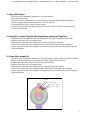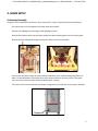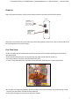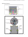
1
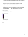
To Purchase This Item, Visit BMI Gaming | www.bmigaming.com | 1-800-746-2255 | + 1-561-391-7200 79MAN-01-E 0 To Purchase This Item, Visit BMI Gaming | www.bmigaming.com | 1-800-746-2255 | + 1-561-391-7200 TABLE OF CONTENTS > MANUAL REVISION HISTORY..................................................................................................................... 2 1- BASIC COMPONENTS ................................................................................................................................ 3 2- GAME PLAY SEQUENCE/BEHAVIOR .......................................................................................................... 4 3- GAME SETUP ............................................................................................................................................. 6 Recommended Payout Settings ............................................................................................................ 8 4- TECHNICAL OPERATION .......................................................................................................................... 10 Inter-Board Communication ............................................................................................................... 10 Main Electronic Components ............................................................................................................. 11 5- PROGRAMMING OPTIONS ...................................................................................................................... 17 6- ALTERNATIVE CONFIGURATIONS............................................................................................................ 20 7- MECHANICAL ......................................................................................................................................... 22 Claw Operation .................................................................................................................................. 22 Service and Adjustment Procedures ................................................................................................. 22 Claw Travel Assembly Removal ................................................................................................ 22 Trap Door Sensor Adjustment .................................................................................................. 24 Claw Cord Replacement ........................................................................................................... 25 Exploded view drawings .................................................................................................................... 26 8- ERROR CODES AND TROUBLESHOOTING GUIDE .................................................................................... 30 1 To Purchase This Item, Visit BMI Gaming | www.bmigaming.com | 1-800-746-2255 | + 1-561-391-7200 MANUAL REVISION HISTORY -08-16-11: REV E -Revised for new firmware version 1.3. Pages 13,14,19 -Revised “Recommended Plush Merchandise” for compatibility with chute revisions. Page 8. -05-10-11: REV-D -Revised for new firmware version 1.2. Pages 13,14,19 -03-02-11: REV-C -Revised ‘Trap Door Sensitivity Adjustment” section -Revised “Recommended Plush Merchandise” and added prize test section -11-30-10: REV-B -Added “Trap Door Sensitivity Adjustment” section. -Added symptom #20 to troubleshooting guide. -Updated “Claw Lift Travel Assembly” drawing sheet 1. -Add gear cover plate side screw removal to “Trap Door Sensor Adjustment” -Update Table of Contents -10-04-10: REV-A Created Benchmark Games Inc. holds exclusive copyright in the Hardware and Software contained within this game machine. Benchmark also owns the copyright in the ARTWORK DESIGNS, MUSIC, and original SOUND EFFECTS that are incorporated in the game machine. No part of this artwork, music, sound effects, images, displays, software or firmware may be reproduced in any way without the express written permission of Benchmark Games Inc. Benchmark Games Inc. also retains other various intellectual property rights in the game machine including pending patent rights, trade dress rights and trademarks. PERSONS WISHING TO MAKE USE OF ANY OF THE INTELLECTUAL PROPERTY DESCRIBED ABOVE SHOULD CONTACT BENCHMARK GAMES INC. IN THE FIRST INSTANCE. Every effort has been made to ensure that the information contained within this manual is accurate. Benchmark Games Inc. reserves the right to make alterations without prior notice. 2 To Purchase This Item, Visit BMI Gaming | www.bmigaming.com | 1-800-746-2255 | + 1-561-391-7200 1- BASIC COMPONENTS Top Access Door Trap Door Flaps Chute Assembly ISO VIEW Automatic Toy Loader Claw Playfield Lights Player Button Trap Door Coin-Mech Two-Digit Display Bill Acceptor Speaker Toy Retrieval Door AC Power Input + Switch LEFT SIDE VIEW Cash Drawer FRONT VIEW RIGHT SIDE VIEW Figure 1. Overview of main components 3 To Purchase This Item, Visit BMI Gaming | www.bmigaming.com | 1-800-746-2255 | + 1-561-391-7200 2- GAME PLAY SEQUENCE/BEHAVIOR I-Power-up initialization Sequence (10 seconds): This is useful to quickly confirm that the machine features are operational. -The Two-Digit Display will flash the firmware version number (i.e “10” for version 1.0) -Claw will start its vertical homing sequence and will arm its latch mechanism, then it will go park at the back of the game. - Simultaneously, the Trap Door will start its homing sequence until it is fully closed and parked or it detects that a toy is already present. -Playfield lights and cabinet lights will glow up and down, confirming operation. -The game will then go into Attraction-mode, or Play-mode, if there were any previous credits saved. II- Attraction Mode: -Various light patterns are shown while the background sound plays on. Note that since this is a ‘Street’ piece, there is a rest period (which is programmable, see section) before these sequence is re-triggered, to avoid becoming repetitive . III- Adding Money (Coin-Mech /Bill Acceptor / Card-swipe system): - “Coin-in” or “bill-in” sound is heard on speaker. - When enough money is added to buy credit(s), the current credits value will be shown on the two-digit Display, and the game will enter Play-Mode IV- Play Mode: - Play-mode start sound “Lightning Bolt” is heard if a prize toy is already loaded on Trap Door - The Playfield Lights will start the clockwise spinning pattern fading in behind a quick ‘glow down’ pattern. They will restart every ten seconds to ensure both top and bottom halves are in synch. 4 To Purchase This Item, Visit BMI Gaming | www.bmigaming.com | 1-800-746-2255 | + 1-561-391-7200 V- Player Hits Button: - Light ‘puck’ stops immediately and flashes in its current position. - Credit will be discounted. - Trap Door will open proportionally by a preset amount (operator programmable) depending on whether the light stopped in the playfield’s x1, x2 or x3 positions. - Trap Door lights flash and “cranking” sound is heard. - If player has more credits, the light spinning will restart for a new try, otherwise the game will go back into Attract-Mode. V- Game Win, normal (Toy falls after progressive opening of Trap Door) - Playfield and Trap Door lights will flash and sound effects will begin, lasting about 10 seconds. -Trap Door will home back to its closed position. - Simultaneously, Claw will automatically look for a new toy to drop on Trap door. Note: Chosen ‘pickup’ position is pseudo-random, optimized to use toy piles more efficiently. - If player has more credits, the machine will continue on play mode, otherwise the game will go back into Attract-Mode. VI- Game Win, Jackpot Hit - Light ‘puck’ stops immediately and flashes in its current position. All other lights turn off for 2 seconds -All lights commence flashing and sound effects will begin, lasting about 25 seconds -Trap Door will open all the way until toy falls down to chute door. -Trap Door will home back to its closed position. - Simultaneously, Claw will automatically look for a new toy to drop on Trap door. Note: Chosen ‘pickup’ position is pseudo-random, optimized to use toy piles more efficiently. - If player has more credits, the machine will continue on play mode, otherwise the game will go back into Attract-Mode. JACKPOT High Trap Door advance Medium Trap Door advance Low Trap Door advance 5 To Purchase This Item, Visit BMI Gaming | www.bmigaming.com | 1-800-746-2255 | + 1-561-391-7200 3- GAME SETUP Unloading/Assembly The game is pre-assembled in the factory; all you have to do is unpack it and check/locate the following: -The cabinet keys are tie-wrapped to the lower chute door handle. -Remove any shipping foam that might still be holding any parts. -Remove the hardware and tie-wraps/foam holding the claw assembly against the back of the game. -Remove the foam/cardboard holding the trap-door flaps on the chute assembly. -Confirm that the claw carriage can travel freely all around the track, without finding obstructions or debris. It should be able to travel both ways to the stopper found on the front-center of the game. Also, the claw’s electrical cables should not bind/snag to anything. -The power cord is stored inside the cash drawer, along with this manual and any spare parts included. 6 To Purchase This Item, Visit BMI Gaming | www.bmigaming.com | 1-800-746-2255 | + 1-561-391-7200 Power up Plug-in the machine and turn it On from the Switch located on the lower-left side of the cabinet. POWER SUPPLY AC INPUT, IEC-C13 PLUG 2 Fuses Within (10A, 250V each) MAIN POWER ON-OFF SWITCH Note: There are two AC fuses on the within the power supply (10Amp, 250V each). They’re found inside of the ICE-C13 receptacle on the power supply. First-Time Setup -If your Trap Door was not ordered with a dollar bill acceptor, we recommend installing one to maximize revenue potential -Ensure that all motors/sensors work by observing the sequence described on section 2-I. Any major anomaly, if present, should be seen at this point. - If a toy is not present within the Trap-Door, let the automatic claw load one, or place one by hand. -Run through the ‘Programming Mode’ options and define your desired settings, like credits settings, sound Volumes, etc (See Section 5 for Benchmark’s defaults). -Confirm your settings to ensure they are what you wanted. 7 To Purchase This Item, Visit BMI Gaming | www.bmigaming.com | 1-800-746-2255 | + 1-561-391-7200 Recommended Plush Merchandise The type and quality of merchandise run in the Trap Door machine will correlate directly to reliability and revenue. Be sure to use the correct size and desirable toys. Size Large prizes up to 16-17” should not be a problem in the Trap Door machine on the later models containing secondary acrylic walls on the sides of the chute above the doors. Toys with very long limbs or snake like toys may need to be tied to keep them from hanging on the top edge of the chute when the prize is dropped from the claw (as shown in picture). Verifying Size If you have any question about the compatibility of a particular toy you should try it in the machine. Allow the claw to lift and deliver the toy to the chute and then play the game until win to verify. Example of Inappropriate toy Note: Tweaking the payout of the Trap Door to low levels will affect your net revenue negatively. Quality merchandise and fair payout (28-35%) should maximize net income. More door movement = more consecutive play = more gross revenue. The player recognizes an investment in the prize as they have paid for the door to move open and will be more apt to insert more money if the doors show generous movement on the way to an inevitable win. Recommended Payout Settings -Section 5 of this manual describes the different Settings that can be used to configure the machine. From those settings, the following are the ones that will most likely affect the payout-percentage and the income of the machine: -Coins-per-credit -Plays-per-credit. -Trap Door Increment -Jackpot Win Window Tolerance. Prize Size and Payout: It should be noted that prize size will contribute to payout percentage variation. Larger prizes will take more plays for the trap doors to open enough to drop the prize for wins when no instant win is hit. Smaller prizes take fewer plays. Therefore large inexpensive prizes will yield a lower payout percentage than smaller expensive prizes using the same configuration settings. Other Considerations: The settings you choose to set the payout, particularly the ‘Trap Door Increment’ and the ‘Jackpot Win Window’, may have a dramatic effect on how much play the machine gets. To maintain the game psychology which makes the player feel he can win and that he is getting significantly closer to a win each play the preferred setting is 3 (2 minimum) on the ‘Trap Door Increment’ and do not go below 2 on the ‘Jackpot Win Window’. 8 To Purchase This Item, Visit BMI Gaming | www.bmigaming.com | 1-800-746-2255 | + 1-561-391-7200 Operators that try to dramatically reduce payout or percentage the machine with too low credit cost combined with too high prize value will be forced to reduce these settings. This will affect the players’ perception of his ability to win and curb his interest in playing. The Excel file TrapDoor_PAYOUT_CALC.xls is a payout estimator for this game, available on the ‘Downloads’ section of our website. This calculator allows you to plug in different configuration values and get an idea of the expected payout %. The following varied examples are some recommended settings that can be tried and later adjusted according to your plush merchandise and demographics. The below examples will get you close to a 33% payout using standard Jumbo sized crane plush. Note that these examples are not necessarily proportional to each other, they just illustrate different ways to configure the game. 25 Cents Per Credit, 1 Play Per credit Average Plush Cost: $1.75 (operator cost) Coins-per-Credit: 1 Trap Door increment: 2 Jackpot Win Window: 2 50 Cents Per Credit, 1 Play Per Credit (Factory Default) Average Plush Cost: $2.70 (operator cost) Coins-per-Credit: 2 Trap Door increment: 3 Jackpot Win Window: 2 1 Dollar Per Credit, 1 Play Per Credit Average Plush Cost: $5.40 (operator cost) Coins-per-Credit: 4 Trap Door increment: 3 Jackpot Win Window: 2 9 To Purchase This Item, Visit BMI Gaming | www.bmigaming.com | 1-800-746-2255 | + 1-561-391-7200 4- TECHNICAL OPERATION Inter-Board Communication The Circuit Boards communicate with each other using a 485 differential wire-pair network, using the SNAP software protocol layer. - On this machine, this wire pair has colors Blue and Gray. - The Main CPU Board acts as the master, initiating commands and receiving responses from the slave boards. - Like-boards differentiate from each other by means of an ID-Switch setting. See the following pages to find each board’s ID-Switch location and setting. - The following board(s) is NOT connected to the 485 network: > The Power distribution board. > The Opto Sensors. -Note that the 485 network wire-pair chain jumps from board to board: > In some places the chaining is done by double-crimps at the connector (these are usually 2-pin connectors) >In other places, PCB traces on the board itself carry the chain from a pair of connector pins to the next (usually a four-pin connector); thus, disconnecting such a board’s 485 might actually disconnect the rest of the 485 chain. Keep this in mind when troubleshooting or replacing parts. -485 Communication network chain: Main CPU (Quad Stepper Board) IO-expander-3 Two-Digit-Display Sound Board IO-Expander-1 (playfield) IO-Expander-2 (playfield) 10 To Purchase This Item, Visit BMI Gaming | www.bmigaming.com | 1-800-746-2255 | + 1-561-391-7200 Main Electronic Components Sound Board (Aluminum Case not shown) Main CPU (Quad Stepper Board) IO-Expander 3 Figure 3. PCB Boards: Top Panel IO-Expander 1 IO-Expander 2 Power Distribution Board (Programming Buttons) Door Closed „Home‟ Position Opto Sensor Right-Hand Door Flap Opto Weight Sensor Left-Hand Door Flap Opto Weight Sensor Figure 4. PCB Boards: Back Panel and Trap Door mechanism 11 To Purchase This Item, Visit BMI Gaming | www.bmigaming.com | 1-800-746-2255 | + 1-561-391-7200 Figure 5. Upper panel Opto sensor Claw vertical Home/Latch Opto Sensor Claw Home/Latch/Slack Flag Disc Figure 6. Claw Vertical Home/Latch Opto Sensor 12 To Purchase This Item, Visit BMI Gaming | www.bmigaming.com | 1-800-746-2255 | + 1-561-391-7200 Power Distribution Board Part# PCB17001 Location: Back Panel. ID-Switch setting: None, board has no computer. Distributes DC power from the power-supply to the different devices, through a Poly-Switch (thermal, resettable fuse) for each voltage circuit. Not that for convenience, the ‘Programming Options’ Buttons are also located on this board, although they’re not power related. Power is distributed in the following manner (worst case estimations): Board/Device Estimated consumption circuit (see board) -Quad Stepper Board (main CPU) + 3 Motors (24V, 3A) -Sound Board (on Top Panel) (12V, 140mA) -IO-Expander 1 (+Playfield Top Lights) (12V, 500mA) -IO-Expander 2 (+Playfield Bottom Lights) (12V, 500mA) -IO-Expander 3 (+Coin/Bill,light-strips) (12V, 4A) - x3 Opto sensors (Trap Door Assy) ( 5V, 60mA) - x2 Opto sensors (Claw Assy) + Credits Display ( 5V, 160mA) Fuse (*24A*) (*12B*) (*12C*) (*12C*) (*12A* + *12D*) [3A peak: Bill Acceptor] (*5A*) (*5B*) Related Note: There are 2 AC fuses on the Power supply group (10Amp, 250 V). They’re found inside of the ICE-C13 receptacle on the power supply. Main CPU Board (Quad Stepper Controller) Part# PCB11006 Location: Back Panel. ID-Switch setting: 00 (off-off) J1: MOTOR DRIVER OUTPUTS ID Switch The stepper-motor controller board handles both the game logic and the low-level control of the game’s motors. This board is the main controller of the game. It decides all the game actions and commands the other boards to act according to the game scheme. Communication to the other boards is performed via a 485 differential wire-pair (Gray and blue wires). The ‘Programming Mode’ game-settings information is saved in on-chip Flash. J2: LOGIC INPUTS J3: Power, 12V 485 Communication Main ROM program Version Updates: 1.3 (08-15-11) Corrected eeprom silicon errata, which affected ‘prorgamming options’ retention 1.2 (05-10-11) -Meter Counts coins, as opposed to credits -Finer resolution accuracy on light-stop.[REQUIRES IO-EXPANDER BOARD WITH 2.3 FIRMWARE]. -Trap door increment range adjusted to more practical values -other internal performance adjustments 1.0 (09-14-10) First release version 13 To Purchase This Item, Visit BMI Gaming | www.bmigaming.com | 1-800-746-2255 | + 1-561-391-7200 IO-Expander 1 J3: OUTPUTS, Open Collector J1: LOGIC INPUTS ID-Switch 485 Communication J2: Power, 12V Part# PCB14008 Location: Back Panel ID-Switch setting: 0000 (off-off-off-off) Top-Half Bottom-Half Handles the 16 LEDs on the top half of the play-field. Light #1 is the one immediately after 9 o’clock, they follow clockwise. The jackpot light is the 8th light. Note: For trap-Door version 1.1 and above, it is recommended (but not required) that IO-expanders have firmware 2.3. IO-Expander 2 Part# PCB14008 Location: Back Panel ID-Switch setting: 1000 (on-off-off-off) Handles the 16 LEDs on the bottom half of the playfield. Light #1 is the one immediately after 3 o’clock, they follow clockwise. IO-Expander 3 Part# PCB14008 Location: Back Panel ID-Switch setting: 0100 (off-on-off-off) Handles the LED strips found on the cabinet columns, the playfield perimeter and in the trap door chute. It also handles the two Accounting Hard-meters (credits count, toys count), as well as the drive enable line going to the coin-mech and Bill Acceptor. 14 To Purchase This Item, Visit BMI Gaming | www.bmigaming.com | 1-800-746-2255 | + 1-561-391-7200 Sound Board Part# PCB18001 Location: Upper Assembly ID-Switch setting: 0000 (off-off-off-off) SD-CARD BAY 485 Communication ID-Switch RCA AUDIO OUTPUT Handles background and event sounds. Sound files are stored on the plug-in SD-card memory board. Power, 12V RCA AUDIO OUTPUT Opto Sensors Part# OPTO4070 [Right Angle Connector] Locations: Claw track and mechanism, and behind Trap Door assembly Qty: x5 ID-Switch setting: None, it has no 485 communication. They detect the following five occurrences: - Claw Vertical Home (Home/latch, cord slack) - Claw Horizontal Home (Back of game, claw track panel) - Trap Door Home (Door closed) - Trap Door Left (flap toy-weight sense) - Trap Door Right (flap toy-weight sense) Notes: This sensor board has a Green LED that lights up when the IR beam is interrupted. All Five sense signals go to the Quad stepper Board Inputs, J2 connector Small 2-Digit Display Part# PCB2DD-010-D [485 capable] Location: Front of Game ID-Switch settings: 0000 (off-off-off-off) The ID-Switch is located on the back of the Display and is labeled as “S1”. Tilt/Shake Sensor Part# GEN00074 Location: Back side of game, behind Claw parking position. Detects when someone shakes the cabinet in an attempt to have the toy fall through Trap Door. The signal goes straight to Main CPU (Quad Stepper Board); The Trap Door will close-back a few degrees and a ten second audible alarm will be set off. Hard-meter Pair 15 To Purchase This Item, Visit BMI Gaming | www.bmigaming.com | 1-800-746-2255 | + 1-561-391-7200 Part# ASM001 [2-in-1 Assembly, with common connector] Or #ELM007 (individual) Qty: x2 meters Location: Cash Drawer Non-resettable type #1 (left) : Credits Purchased Count #2(Right): Toy Vend Count Coin Mech (factory default) Imonex 0.900 type with Coin Lock Solenoid Part# ELM-014 Location: Front of Game Bill Acceptor (Optional) MARS Mei 2451 or 2681 (115VAC Models) Location: Cash Drawer Default Benchmark Games Operational Settings: This is done by setting the side configuration Dip-Switches as follows: MARS AE2681 MARS AE2451 On OFF Setting Obtained: OFF On Setting Obtained: 1 4-way accept 8 Vending Interface 2 4-way accept High Security 7 6 1-Pulse-per Dollar Harness Enable 4 $1 5 $20 5 no $2s 4 no $2s 6 $5 3 High Security 7 1-Pulse-per-Dollar 2 4-way accept 8 Harness Enable 1 4-way accept 3 Enable/Disable feature (Game controlled): [Note that we provide the appropriate adaptor harness/connector for this bill acceptor] (+5V) 16 To Purchase This Item, Visit BMI Gaming | www.bmigaming.com | 1-800-746-2255 | + 1-561-391-7200 5- PROGRAMMING OPTIONS MENU COINS PER CREDIT Press Upper and Lower buttons simultaneously to enter Programming Mode PLAYS PER CREDIT ATTRACTION VOLUME PLAY VOLUME Upper Button JACKPOT VOLUME TILT/SHAKE ALARM VOLUME FIVE DOLLAR INCENTIVE “Enter” Button Lower Button TEN DOLLAR INCENTIVE TWENTY DOLLAR INCENTIVE ATTRACTION REPEAT PERIOD TRAP DOOR INCREMENT Playfield panel WIN WINDOW TOLERANCE Power Distribution Board -Behind Playfield panel- CLEAR CREDITS EXIT Figure 7. Programming Mode Scheme. Button Assignments: “Upper”: Increment Value “Enter”: Save option value and advance to next option “Lower”: Decrement Value To enter Programming mode, press Upper and Lower buttons on the Power Distribution Board, by reaching behind the Playfield Panel, on the right, as shown in figure 8. The menu is followed in a sequential order, by using the center button to advance through the options. Once you enter Programming Mode: As you go through the menu, each option number will appear in the small two-digit display, the name will be called by a voice, and the value set will be displayed by the top-left quadrant playfield-lights, acting as a tach. Possible values displayed are: 0 (all dim) and 1 to 8 highlighted. Figure 8. Programming value tach range, 1 to 8 PROGRAMMING MENU 17 To Purchase This Item, Visit BMI Gaming | www.bmigaming.com | 1-800-746-2255 | + 1-561-391-7200 1- COINS PER CREDIT How many Coin-Mech pulses are required to add +1 credit. Value Range: 0 – 8 Default: 2 note: ‘0’ is meant as a demo-mode, when showcasing the game. Notes: -One Bill Acceptor pulse will count as four coins internally (i.e. $1= $0.25 x4) -Actual coin value is determined by your coin-mech/swipe-card configuration, * i.e. the ‘coin’ could be $0.25 or $1.00, without the game having to be aware of this + 2- PLAYS PER CREDIT How many play-tries are allowed per each purchased credit. This allows to set for example: 3 tries for $1 , etc. Value Range: 1 – 8 Default: 1 3-ATTRACTION VOLUME Background music volume, when outside of play mode Value Range: 0-8 (0-100%) Default: 25% 4- PLAY VOLUME Background music and event volume, when Player has credits. Value Range: 0-8 (0-100%) Default: 30% 5- JACKPOT VOLUME Background music and event volume when Player wins toy, regardless of it being through Jackpot or not. Value Range: 0-8 (0-100%) Default: 50% 6- TILT/SHAKE ALARM VOLUME The volume for the alarm sound set off when someone shakes the machine. Value Range: 0-8 (0-100%) Default: 50% 7-FIVE DOLLAR INCENTIVE How many extra credits are given when the player introduces at least $5 (accumulated in coins or bills) before pressing the play button. Note that these extra credits will then be multiplied by the ‘Plays per Credit’ option value. Value Range: 0-6 Default: 1 8-TEN DOLLAR INCENTIVE How many extra credits are given when Player introduces at least $10 (accumulated in coins or bills) before pressing the play button. Note that this value already accounts for the ‘Five Dollar Incentive’ option value. Value Range: 0-8 Default: 2 9-TWENTY DOLLAR INCENTIVE 18 To Purchase This Item, Visit BMI Gaming | www.bmigaming.com | 1-800-746-2255 | + 1-561-391-7200 How many extra credits are given when Player introduces at least $20 (accumulated in coins or bills) before pressing the play button. Note that this value already accounts for the ‘Ten Dollar Incentive’ option value. Value Range: 0-8 Default: 3 10-ATTRACTION PERIOD Length of time before the attraction fan-fare repeats when there are no credits present on machine. Value Range: 0-8 Default: 1 Note: 0=off(no attraction) 1 to 8 = 5 to 40 minutes 11- TRAP DOOR INCREMENT Proportion by which trap door opens on play mode. All three x1, x2, x3 playfield hits are proportional to this setting. Value Range: 1-8 (small – large) Default: 5 Example: For a setting of 3, a “1x hit” will move the door by about 3° 12-WIN WINDOW TOLERANCE The width of the jackpot window. Value Range: 1-8 (harder - easier) Default: 5 13- CLEAR CREDITS Return the credits to zero. Press either the Upper or lower button to clear. Then press ‘Enter’(middle button) again to continue. 14-EXIT 19 To Purchase This Item, Visit BMI Gaming | www.bmigaming.com | 1-800-746-2255 | + 1-561-391-7200 6- ALTERNATE COIN/BILL AND CARD-SWIPE SYSTEM CONFIGURATIONS There are a few alternative configurations regarding Card Swipe systems and Bill Acceptor devices that are possible to setup, depending on your location. These are described in a general fashion as follows. Note that the system expects the following timing ranges for any pulses: Low time: 40-80mS Up time: 100-150ms CARD SWIPE SYSTEM The Coin-Mech and/or Bill Acceptor can be replaced to set up a swipe-for-credits scheme. The recommended set up is as follows: -Remove the Coin-Mech and/or Bill Acceptor and install your card swipe systems in one of the two spots. [contact customer service for custom plastic plates for this purpose]. -Have your card swipe system tap into the Coin or Bill signal line. -Configure your card swipe system for a 1-pulse-per-swipe response. -If tapping the coin signal line (Gray–Red wire), 1 pulse (swipe) will count as 1 coin internally. -If tapping the bill signal line (Gray-Green wire), 1 pulse (swipe) will count as 4 coins internally. -Configure the game to provide the necessary credits for the ‘coin’ count indicated above and the actual money you will charge per-swipe. -If possible (strongly recommended), hook up your system to the enable line (Blue-Green wire), so that the game can stop money intake in case of any error or fault. -Additionally, if your scheme supports/requires accounting, you can tap from the pulse signal (White-Blue wire) going to Hard-meter box #2 (see page 16), which tracks the number of toys vended. 20 To Purchase This Item, Visit BMI Gaming | www.bmigaming.com | 1-800-746-2255 | + 1-561-391-7200 COIN MECHS It is possible to use other coin mechanisms on this machine. The wiring harness terminates on both Spade-type connectors and an IDC connector for this purpose, the signal lines are: # 1 2 3 4 Wire Color Yellow Gray-Red Blue-Green Black Signal 12V Coin Signal Enable (low=enable, high=disable) (this should be hooked to coin-mech ground) GND, actual DC Ground Notes: The ‘Device Ground/Enable line comes from the IO-Expander 3 Board, as commanded by the main CPU to enable or disable money intake. It is necessary that your coin-mech device has a coin-lock ‘reject’ solenoid so that this feature is available. Normally, for an Imonex, if it has a coin reject solenoid, you hook the solenoid’s ‘ground’ to the enable line, so that the game can control it. For an electronic coin-mech, like the MPU, you hook up the coin-mech’s ‘ground’ to the enable line. BILL ACCEPTORS It is possible to use other bill acceptors on this machine, like the IT-Bellis BV50, or the Pyramid Apex 5000 Series. The wiring harness on the Cash Drawer terminates on a 12-Pin Molex female connector, providing all the necessary signal lines: Pin 1 2 3 4 5 6 7 8-12 Wire color Red Yellow Black Gray-Green Blue-Green White Black -- Signal 5V 12V GND, actual DC Ground Bill Pulse Signal Enable (low=enable, high=disable) (same ‘Enable’ line as for coin-mech above) AC Neutral AC Hot Reserved This connector is followed by an adaptor harness for the appropriate device. We stock adaptor harnesses for the Mars 2451, the IT-Bellis BV50 and the Pyramid bill acceptors. [Please note that we strongly recommend a device that supports a Logic-Enable line, so that the game can stop money intake in case of any error or fault]. Please contact customer service if necessary. 21 To Purchase This Item, Visit BMI Gaming | www.bmigaming.com | 1-800-746-2255 | + 1-561-391-7200 7- MECHANICAL Claw Operation The Trap Door claw uses a “mouse trap” style mechanism for activation. There is no sensitivity adjustment. The claw is activated when the weight of the claw rests on the trip sensor plate upon descending onto a prize. The claw is set open when it is lifted up into the travel assembly. It is normal that the claw will not activate every time due to the nature of bulk prize storage in the prize bin. “Holes” in the top layer of product may not allow enough pressure directly on the trip sensor plate to activate the claw in some instances. If this occurs, or if the claw just misses a prize, the machine will continue to cycle the load sequence until a prize is finally loaded. Service and Adjustment Procedures Claw Travel Assembly Removal 1. 2. 3. 4. Power machine off Loosen (2) lower roller mount screws Disconnect harness Lift assembly up and out of track. Do not force assembly out as you may bend the bracket. If necessary, loosen the (4) motor mount screws and allow motor to fall to its lowest position to allow more clearance before lifting assembly out. To replace, reverse above procedure. Trap Door Sensor Adjustment (Use this procedure if the trap doors are uneven (one higher than the other) with no prize in the chute.) 1. Power machine off. 2. Remove all toys from machine. 3. Remove (2) gear cover plate screws and (4) cover plate side screws (2 on each side). 4. Remove gear cover plate. 5. Loosen right side shaft collar. 6. Remove right side gear and pin plate and allow the right side trap door to raise completely. 22 To Purchase This Item, Visit BMI Gaming | www.bmigaming.com | 1-800-746-2255 | + 1-561-391-7200 7. Replace the right side gear on the shaft so that the opto flag is in the up position and within the opto “horseshoe” when engaged with the worm gear. 8. Replace the right side pin plate on the shaft, turn the pin plate clockwise until it stops on the opto mount spacer while the right side trap door is in the up limit position, and tighten the shaft collar. 9. Loosen the left side shaft collar and allow left side trap door to raise completely. 10. Turn the left side pin plate completely counterclockwise until it stops on the opto mount spacer while the left side trap door is in the up limit position, and tighten the shaft collar. 11. Replace gear cover plate and screws. 23 To Purchase This Item, Visit BMI Gaming | www.bmigaming.com | 1-800-746-2255 | + 1-561-391-7200 Trap Door Sensitivity Adjustment (Use this procedure to adjust the sensitivity of the prize sensing on the doors.) 1. Power the machine off and then on again with no prize in the chute allowing the boot up sequence to take place. 2. Power the machine off (trap doors should be horizontal or slightly angled up). 3. Loosen trap door attaching screws on one of the doors. 4. Adjust the door so that it is at the slot limit toward the center of the chute and tighten one of the trap door attaching screws to hold in place. 5. Test this setting by gently pushing the door down about ½” to see if it will return up reliably. a. If the door returns up reliably, tighten remaining screws. b. If the door remains down or does not reliably return up, loosen the trap door attaching screw and slide the door back slightly toward the side of the chute and retest. Repeat until the door returns up reliably, but stays as sensitive as possible. 6. Repeat steps 3-5 on the other door. 7. Verify Operation a. With the doors in the up position, place the lightest prize that will be used in the machine on the doors. The prize should easily depress the doors and activate the sensors notifying the computer that there is a prize in the chute. b. Remove the small, light prize and place the largest prize that will be used in the machine. This prize should require that the doors open almost completely before dropping. c. Play the machine without hitting the jackpot until the prize drops. When the prize drops, the counterweights should cause the doors to immediately return slightly notifying the computer that a prize has dropped. The machine should then return the doors to the up position and continue normal operation. If the doors do not return at all after dropping the prize and the machine doesn’t know the prize has dropped, the doors need to be adjusted in the slots away from the center of the chute. Adjust them out slightly and repeat steps 5-7. 24 To Purchase This Item, Visit BMI Gaming | www.bmigaming.com | 1-800-746-2255 | + 1-561-391-7200 Claw Cord Replacement Notes: Use Benchmark supplied cord to insure proper operation. You may perform cord replacement with the claw travel assembly within the game or removed. 1. Cut old cord and remove claw. 2. Remove cord from lift reel. 3. Feed new cord up through claw position rod, claw reset hoop, and claw centering plate. 4. Feed string through the cord guide spacer: a. Position the cord guide spacer so that the cross drilled hole is offset to the left of the pivot spacer. b. Feed the string through the cord guide spacer and to the left of the pivot spacer as shown (very important). c. Feed the cord through the cable pulley and tie a knot to secure. d. Trim cord above knot. e. Take up the slack by turning the large timing belt pulley in the up feed direction at least until claw is suspended by the cord and not sitting on the prize bin floor. f. Power machine on and verify operation. 25 To Purchase This Item, Visit BMI Gaming | www.bmigaming.com | 1-800-746-2255 | + 1-561-391-7200 26 To Purchase This Item, Visit BMI Gaming | www.bmigaming.com | 1-800-746-2255 | + 1-561-391-7200 27 To Purchase This Item, Visit BMI Gaming | www.bmigaming.com | 1-800-746-2255 | + 1-561-391-7200 28 To Purchase This Item, Visit BMI Gaming | www.bmigaming.com | 1-800-746-2255 | + 1-561-391-7200 29 To Purchase This Item, Visit BMI Gaming | www.bmigaming.com | 1-800-746-2255 | + 1-561-391-7200 8- ERROR CODES AND TROUBLESHOOTING GUIDE ERROR CODES, QUICK SUMMARY Shown on the red 2-Digit Display. E1: E2: E3: E4: E5: E6: E7: E8: E9: EA: Eb: EC: IO-Expander 1 (Playfield Top-half), Communication Error. IO-Expander 2 (Playfield Bottom-half), Communication Error. IO-Expander 3, Communication Error. Sound Board, Communication Error. Two Digit Display, Communication Error. Out-of-Plush Condition. Toy Stuck Error. Claw Horizontal Homing Error. Claw Vertical Homing Error. Trap Door Homing Error. Trap Door Load Error. Tilted/Shaken Cabinet. TROUBLESHOOTING GUIDE # SYMPTOM POSSIBLE CAUSES / ACTIONS SEE RELATED SYMPTOMS: 0 It doesn't work Multiple. Plug the game to a wall receptacle and determine more exactly what features don't work. All 1 E1 Error Code: IO-Expander 1 (Playfield top-half) Communication Error Most likely top-half of playfield lights will behave erratically or will show nothing at all. > Check board has power, Vcc-LED should be lit. > Check board program is running, heartbeat LED should be flashing slowly, fast when receiving 485 serial comm. Commands. > Check on-board ID-switch setting, should be Off-Off-Off-Off. > Check 485 communication connector for proper crimping and polarity (try flipping 485 connector or its pins) > Check that all boards are connected to the 485 network, remember that in some of them, a disconnection will break the rest of the 485 chain. > Check 485 communication connector on Main CPU Board 3,4 2 E2 Error Code: IO-Expander 2 (Playfield bottom-half) Communication Error Most likely bottom-half of playfield lights will behave erratically or will show nothing at all. > Check board has power, Vcc-LED should be lit. > Check board program is running, heartbeat LED should be flashing slowly, fast when receiving 485 serial comm. Commands. > Check on-board ID-switch setting, should be On-off-off-off. > Check 485 communication connector for proper crimping and polarity (try flipping 485 connector or its pins) > Check that all boards are connected to the 485 network, remember that in some of them, a disconnection will break the rest of the 485 chain. > Check 485 communication connector on Main CPU Board 1,3,4 3 E3 Error Code: IO-Expander 3 (Auxiliary IO control) Communication Error This board controls the Playfield backlights, the trap door lights, the column lights, the accounting hard-meters, and the failure of these can be a symptom to confirm the E3 Error. > Check board has power, Vcc-LED should be lit. > Check board program is running, heartbeat LED should be flashing slowly, fast when receiving 485 serial comm. Commands. > Check on-board ID-switch setting, should be On-off-off-off. > Check 485 communication connector for proper crimping and polarity (try flipping 485 connector or its pins) > Check that all boards are connected to the 485 network, remember that in some of them, a disconnection will break the rest of the 485 chain. > Check 485 communication connector on Main CPU Board (Quad stepper Board) 1,2,4 4 E4 Error Code: Sound Board Communication Error > Check for Sound Board power (Vcc LED On) > Check Sound Board program is running, (green LED flashes slowly) > Check Sound Board communication-485, including on-board ID-switch setting. 3 30 To Purchase This Item, Visit BMI Gaming | www.bmigaming.com | 1-800-746-2255 | + 1-561-391-7200 5 E5 Error Code: Two Digit Display Communication Error 6 E6 Error Code: Out-of-Plush Condition 7 E7 Error Code: Toy-Stuck on Trap Door Condition 8 E8 Error Code: Claw Horizontal Homing Error 9 E9 Error Code: Claw Vertical Homing Error 10 EA Error Code: Trap Door Homing Error 11 Eb Error Code: Trap Door Loading 12 Ec Error Code: Tilted/Shaken Game 13 Trap Door Past upper home position 14 Claw stuck over Trap door can’t find center position on back 15 Claw won’t reach vertical home/latch l 16 17 One of the Light Strips is dead >Add Plush, reboot machine. >The system senses the Door is all the way open but the doors don’t unload (no toy fall) check the door flap Opto sensors and/or the counter-weight mechanism. >The plush being used is indeed to large for the door. Toy sno larger than 17” are recommended. >Check that claw carriage assembly is not stuck and free to move around track all the way to the stop at the front. > Check Opto on back of Claw travel assembly. Remove small top access door to do this. > Check Home opto lights up when claw carriage assembly flag covers it. >If opto seems ok, measure continuitiy on the signal line from opto to quad stepper board inputs. 14 > Check Opto-Flag- disc covers vertical Home-opto when latching claw, or when there is slack on the string. > Check Claw vertical-Home opto lights up when flag-disc covers it. >If opto seems ok, measure continuitiy on the signal line from opto to quad stepper board inputs. 11,14 > Check Trap Door Home Opto lights up when door assembly flag covers it. >If opto seems ok, measure continuitiy on the signal line from opto to quad stepper board inputs. >Check if Claw has any trouble latching its mechanism. >Check Trap Door flap Optos for proper operation. 9,15 >There is a tilt sensor at the back of the game. This alarm should last no more than 10 seconds and then go away. If the condition persist, the sensor may be stuck to the contact rim. Check the position/ alignment of this sensor. >Make sure the sensor line is not getting grounded by any other wire around the cabinet. The line should not have 0V unless the sensor makes contatct. > Check Trap Door Home Opto lights up when door assembly flag covers it. >If opto seems ok, measure continuitiy on the signal line from opto to quad stepper board inputs. >Check proper assembly and orientation of all parts in the pulley assembly, especially if a string replacement was just performed. 7 >Check that the claw carriage assembly is not stuck on the travel limit stop screw at the front of the track over the trap doors. >Check claw carraige home opto for operation and that flag on travel assembly interrupts opto when passing through sensor. >Make sure string is wound the in the proper direction >If the claw is all the way down at the bottom, this might be creating slack on the string, fooling the detection mechanism. Wind the string so that the claw hangs about a foot from the bottom loading the mechanism; the opto should be unblocked at this point; turn on the machine. 9,11 >On Power-up, measure the voltage across the strip (remove the tape covering the solder-points if necessary). You should see 12V sporaidically. As the signal goes through the attraction patterns. >Check for 12V on the yellow wire only, against DC ground on the power distribution board. >Check continuity between the signal wire (Sink) and the corresponding IO-expander3 board (top-panel) output. Claw picks up more than one toy at >This is somewhat rare but normal behavior, depending on the size of the toys being used. a time. 18 Won’t accept Bills/Coins 19 Claw won’t latch open at end of vertical Travel 20 > Check for Sound Board power (Vcc LED On) > Check Sound Board program is running, (green LED flashes slowly) > Check Sound Board communication-485, including on-board ID-switch setting. >The game does disable the coins/bill when there is a E fault code present, check for that. >Check the signals on the interface connector on the Cash Drawer, (12-pin Molex connector) as per section6 (page 22) >make sure those signals go past the interface connector and reach the actual Bill Acceptor connector >Check continuity between the Enable signal wire (sink) and the corresponding IO-expander3 board (top-panel) output. >Check that the lift motor belt pulleys or string pulley are not slipping on the shafts. >Check claw vertical home sensor operation. If upper limit opto is not working, the claw will continue past its latch position and slip down and unlatch. >Check proper assembly and orientation of all parts in the pulley assembly, especially if a string replacement was just performed. 9,11,15 Problem: Trap doors are not adjusted sensitive enough. The cause of the problem is a prize, when of a certain size and weight, is dropped on the chute in Game Jackpots but prize remains in such a way that as the door opens, the weight sensing opto(s) located in the back of the chute are activated before the prize is dropped. The game thinks chute. Usually the claw will stop the prize has dropped and begins to return the trap doors back to the up position when it will almost immediately reset the opto letting the game know short of reloading a prize before there is a prize n the chute. play is allowed to continue Solution: Perform “Trap Door Sensitivity Adjustment” described in this manual 31