1
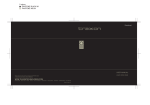
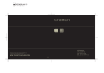
2 colors
PANTONE BLACK M
PANTONE 400 M
USER MANUAL
FLOODLIGHT 3/225 RGB
Please check for the latest updates and changes on the TRAXON website.
©TRAXON TECHNOLOGIES ALL RIGHTS RESERVED.
WWW.TRAXONTECHNOLOGIES.COM
HONG KONG
NEW YORK
PARIS
TOKYO
RIO DE JANEIRO
FRANKFURT
MELBOURNE
SHANGHAI
BIRMINGHAM
ROTTERDAM
Manual - Version 1.0
1 color
PANTONE BLACK M
USER MANUAL & WARRANTY
1. INTRODUCTION: P1
2. CONTENTS: P1
3. SAFETY AND OPERATION: P2
4. PRODUCT DESCRIPTION: P3
5. INSTALLATION AND SYSTEM CONFIGURATION: P3-10
5-1 MOUNTING: P3-4
5-2 DATA CONNECTION: P4
5-3 DMX START ADDRESSING: P5-8
5-4 POWER CONNECTION: P9-10
5-4 CONTROL PROTOCOL: P10
6. CARE AND MAINTENANCE: P11
7. TECHNICAL SPECIFICATION: P11-12
8. WARRANTY: P12
1 color
PANTONE BLACK M
FOR YOUR OWN SAFETY AND OF THE PRODUCT, PLEASE READ THIS USER
GUIDE CAREFULLY BEFORE BEGINNING SET-UP AND INSTALLATION!
3. SAFETY AND OPERATION
CAUTION – UNPLUG THE POWER SUPPLY FROM MAINS POWER BEFORE
CONNECTING ANY CABLES AS THIS CAN DAMAGE THE PRODUCTS !
1. INTRODUCTION
FLOODLIGHT 3/225 RGB (DMX) LU-FL-50100
CAUTION – AVOID LOOKING DIRECTLY INTO THE LED LIGHT SOURCE AT CLOSE
The FLOODLIGHT 3/225 RGB is part of the Traxon™ Luminaires product group, enabling the
RANGE FOR YOUR OWN SAFETY.
use of an RGB LED color changing floodlight in an easy to install surface mount housing. Its
large square lamp unit provides a generous and powerful light output while DMX512 control the
FLOODLIGHT 3/225 RGB to be easily daisy-chained for stunning light effects on a large scale.
192mm/7.56”
Adjustment
• XLR Data Cabling
DMX address
Dip swtich
• External Power Supply
Ø120mm/4.72”
FRONT
SIDE
Lamp Base
BACK
If the fixture has been subjected to drastic temperature variances e.g. following transportation,
do not power on the fixture until it has reached room temperature, as internal condensation
buildup may damage the fixtures electronics.
When installing the fixtures and system power supplies in the chosen locations please be sure
they will not be exposed to moisture, extreme heat or direct sunlight and that it is in a dirt and
dust free environment keeping the fixtures and system power supplies within their operating
boundaries.
1 X Hex Key B.S. 7’32”
1
HANDLING OF ELECTRICAL EQUIPMENT.
An ambient operating air temperature range of 0°C~+50°C (+32°F ~ +122°F) must be
adhered to at all times
2. CONTENTS
1 x Floodlight 3/225 (DMX)
STANDARDS AND REGULATIONS AND MUST BE QUALIFIED TO FOR THE
This product is designed for indoor use only
fi
fl
• DMX512 Control
192mm/7.56”
• 675 Ultra Bright LEDs
Lamp Unit
137mm/5.39”
65mm/
2.56”
283mm/11.14”
• 160° Tilt & 320° Pan Manual
ANY PERSONS INSTALLING THIS PRODUCT SHOULD COMPLY WITH LOCAL
1 x 15VDC Power Supply & AC Cable
2 X Washers
1 X Hex Key #5
1 X Hex Key #2.5
Please study all functions thoroughly via this User Manual and the latest Technical
Specifications Sheets available from our website [www.traxontechnologies.com] before set-up.
2 X Mounting Screws
2
fi
fl
1 color
PANTONE BLACK M
4. PRODUCT DESCRIPTION
Located on the side of the head of the unit
The ‘Floodlight 3/225’ is part of the Luminaires product group and features include low power
screws to lock the fixture into position
consumption, high light output with an even beam spread of 30 ° and control via DMX512 with
once the required focal position has been
XLR 3Pin DMX connectors with DMX Start Address setting via the DIP Switch selector (located
selected, use the Hex Keys provided to
under the safety cover on the rear of the fixture head). The focal position can be adjusted and
lock the Hex Screws firmly in place (FIG 2).
FIG 2
and also on the lamp base are locking hex
locked via the hex screw mechanism with 320 ° Base and 160 ° Head locking rotation, all powered by
Ø120mm/4.72”
a low voltage external power supply for easy installation.
5. INSTALLATION AND SYSTEM CONFIGURATION
5-2 DATA CONNECTION
5-1 MOUNTING
Data connection is via the XLR DMX
FIG 3
connectors, which are hard wired into the
For installation, first unscrew the lamp unit
fixture head and can be linked together in
FIG 1
(FIG 1). Next, unscrew the nut in the centre
of the base fixture, separating it from the
2
a daisy configuration for control on one
from the base in order to access the cover
137mm/5.39”
3
DMX line.
1
For connection, follow the DMX IN and
65mm/2.56”
DMX OUT connector as per the drawing
‘Floodlight3/225’ and take care to keep the 2
below (FIG3), with DMX IN being the male
mounting holes perpendicular to the direction
connector and DMX OUT being the female
that the ‘Floodlight’ will face and fix firmly to
connector and firmly connect each fixture
the chosen flat surface with the mounting
together making sure the locking
fi
fl
base plate. Select the desired location for the
screws and washers supplied. Once the
mechanism is activated.
base plate is fixed firmly in place, re-attach
Should it be required to connect a data
the head to the base and centre locking nut.
extension cable or starter cable, please
Reaffix the lamp unit and reinsert the entry
DMX OUT
1 - GROUND
2 - DATA 3 - DATA +
1
DMX IN
3
2
1 - GROUND
2 - DATA 3 - DATA +
also refer to the diagram (FIG3).
gland.
Ø120mm/4.72”
3
4
1 color
PANTONE BLACK M
5-3 DMX START ADDRESSING
DMX Address 1
3
4
5
6
7
8
9
10
2
3
4
5
6
7
8
9
10
0
0
0
1
1
0
0
0
0
1
151-153
0
0
0
0
1
0
1
0
0
1
58-60
1
0
0
1
1
0
0
0
0
1
154-156
1
0
0
0
1
0
1
0
0
1
61-63
0
0
0
0
0
1
0
0
0
1
157-159
0
1
0
0
1
0
1
0
0
1
64-66
1
0
0
0
0
1
0
0
0
1
160-162
1
1
0
0
1
0
1
0
0
1
DMX repeater. To set the DMX Start
67-69
0
1
0
0
0
1
0
0
0
1
163-165
0
0
1
0
1
0
1
0
0
1
Address, please remove the clear cover
70-72
1
1
0
0
0
1
0
0
0
1
166-168
1
0
1
0
1
0
1
0
0
1
73-75
0
0
1
0
0
1
0
0
0
1
169-171
0
1
1
0
1
0
1
0
0
1
76-78
1
0
1
0
0
1
0
0
0
1
172-174
1
1
1
0
1
0
1
0
0
1
79-81
0
1
1
0
0
1
0
0
0
1
175-177
0
0
0
1
1
0
1
0
0
1
82-84
1
1
1
0
0
1
0
0
0
1
178-180
1
0
0
1
1
0
1
0
0
1
85-87
0
0
0
1
0
1
0
0
0
1
181-183
0
0
0
0
0
1
1
0
0
1
88-90
1
0
0
1
0
1
0
0
0
1
184-186
1
0
0
0
0
1
1
0
0
1
91-93
0
0
0
0
1
1
0
0
0
1
187-189
0
1
0
0
0
1
1
0
0
1
94-96
1
0
0
0
1
1
0
0
0
1
190-192
1
1
0
0
0
1
1
0
0
1
97-99
0
1
0
0
1
1
0
0
0
1
193-195
0
0
1
0
0
1
1
0
0
1
100-102
1
1
0
0
1
1
0
0
0
1
196-198
1
0
1
0
0
1
1
0
0
1
103-105
0
0
1
0
1
1
0
0
0
1
199-201
0
1
1
0
0
1
1
0
0
1
106-108
1
0
1
0
1
1
0
0
0
1
202-204
1
1
1
0
0
1
1
0
0
1
109-111
0
1
1
0
1
1
0
0
0
1
205-207
0
0
0
1
0
1
1
0
0
1
112-114
1
1
1
0
1
1
0
0
0
1
208-210
1
0
0
1
0
1
1
0
0
1
115-117
0
0
0
1
1
1
0
0
0
1
211-213
0
0
0
0
1
1
1
0
0
1
118-120
1
0
0
1
1
1
0
0
0
1
214-216
1
0
0
0
1
1
1
0
0
1
For DMX data connection, a maximum of
FIG 4
32 fixtures can be connected to in a
DMX address
Dip swtich
Lamp Unit
283mm/11.14”
daisy-chain configuration without use of a
on the rear of the head to access the DIP
SWITCH. (FIG 4)
Lamp Base
BACK
NOTE: Please be sure to reset the power to the fixture should the DIP SWITCH be changed to
another setting in order to reset the Start Address.
PLEASE NOTE – DIP SWITCH ‘10’ SHOULD ALWAYS BE IN THE ‘ON’ (UP) POSITION
Please refer to the start address table for reference of the required DIP SWITCH settings:
(DIP Switch Setting:
DMX Address 1
5
DMX Address 1
2
55-57
0 = OFF
1 = ON)
2
3
4
5
6
7
8
9
10
DMX Address 1
2
3
4
5
6
7
8
9
10
121-123
0
0
0
0
0
0
1
0
0
1
217-219
0
1
0
0
1
1
1
0
0
1
1 - 3
0
0
0
0
0
0
0
0
0
1
28-30
1
0
0
1
0
0
0
0
0
1
124-126
1
0
0
0
0
0
1
0
0
1
220-222
1
1
0
0
1
1
1
0
0
1
4 - 6
1
0
0
0
0
0
0
0
0
1
31-33
0
0
0
0
1
0
0
0
0
1
127-129
0
1
0
0
0
0
1
0
0
1
223-225
0
0
1
0
1
1
1
0
0
1
7 - 9
0
1
0
0
0
0
0
0
0
1
34-36
1
0
0
0
1
0
0
0
0
1
130-132
1
1
0
0
0
0
1
0
0
1
226-228
1
0
1
0
1
1
1
0
0
1
10-12
1
1
0
0
0
0
0
0
0
1
37-39
0
1
0
0
1
0
0
0
0
1
133-135
0
0
1
0
0
0
1
0
0
1
229-231
0
1
1
0
1
1
1
0
0
1
13-15
0
0
1
0
0
0
0
0
0
1
40-42
1
1
0
0
1
0
0
0
0
1
136-138
1
0
1
0
0
0
1
0
0
1
232-234
1
1
1
0
1
1
1
0
0
1
16-18
1
0
1
0
0
0
0
0
0
1
43-45
0
0
1
0
1
0
0
0
0
1
139-141
0
1
1
0
0
0
1
0
0
1
235-237
0
0
0
1
1
1
1
0
0
1
19-21
0
1
1
0
0
0
0
0
0
1
46-48
1
0
1
0
1
0
0
0
0
1
142-144
1
1
1
0
0
0
1
0
0
1
238-240
1
0
0
1
1
1
1
0
0
1
22-24
1
1
1
0
0
0
0
0
0
1
49-51
0
1
1
0
1
0
0
0
0
1
145-147
0
0
0
1
0
0
1
0
0
1
241-243
0
0
0
0
0
0
0
1
0
1
25-27
0
0
0
1
0
0
0
0
0
1
52-54
1
1
1
0
1
0
0
0
0
1
148-150
1
0
0
1
0
0
1
0
0
1
244-246
1
0
0
0
0
0
0
1
0
1
6
1 color
PANTONE BLACK M
DMX Address 1
7
DMX Address 1
DMX Address 1
DMX Address 1
2
3
4
5
6
7
8
9
10
2
3
4
5
6
7
8
9
10
2
3
4
5
6
7
8
9
10
2
3
4
5
6
7
8
9
10
247-249
0
1
0
0
0
0
0
1
0
1
343-345
0
0
1
0
1
0
0
0
1
1
439-441
0
1
1
0
0
0
1
0
1
1
475-477
0
0
0
1
0
0
1
0
1
1
250-252
1
1
0
0
0
0
0
1
0
1
346-348
1
0
1
0
1
0
0
0
1
1
442-444
1
1
1
0
0
0
1
0
1
1
478-480
1
0
0
1
0
0
1
0
1
1
253-255
0
0
1
0
0
0
0
1
0
1
349-351
0
1
1
0
1
0
0
0
1
1
445-447
0
0
0
1
0
0
1
0
1
1
481-483
0
0
0
0
0
1
1
0
1
1
256-258
1
0
1
0
0
0
0
1
0
1
352-354
1
1
1
0
1
0
0
0
1
1
448-450
1
0
0
1
0
0
1
0
1
1
484-486
1
0
0
0
0
1
1
0
1
1
259-261
0
1
1
0
0
0
0
1
0
1
355-357
0
0
0
1
1
0
0
0
1
1
451-453
0
0
0
0
1
0
1
0
1
1
487-489
0
1
0
0
0
1
1
0
1
1
262-264
1
1
1
0
0
0
0
1
0
1
358-360
1
0
0
1
1
0
0
0
1
1
454-456
1
0
0
0
1
0
1
0
1
1
490-492
1
1
0
0
0
1
1
0
1
1
265-267
0
0
0
1
0
0
0
1
0
1
361-363
0
0
0
0
0
1
0
0
1
1
457-459
0
1
0
0
1
0
1
0
1
1
493-495
0
0
1
0
0
1
1
0
1
1
268-270
1
0
0
1
0
0
0
1
0
1
364-366
1
0
0
0
0
1
0
0
1
1
460-462
1
1
0
0
1
0
1
0
1
1
496-498
1
0
1
0
0
1
1
0
1
1
271-273
0
0
0
0
1
0
0
1
0
1
367-369
0
1
0
0
0
1
0
0
1
1
463-465
0
0
1
0
1
0
1
0
1
1
499-501
0
1
1
0
0
1
1
0
1
1
274-276
1
0
0
0
1
0
0
1
0
1
370-372
1
1
0
0
0
1
0
0
1
1
466-468
1
0
1
0
0
0
1
0
1
1
502-504
1
1
1
0
0
1
1
0
1
1
277-279
0
1
0
0
1
0
0
1
0
1
373-375
0
0
1
0
0
1
0
0
1
1
469-471
0
1
1
0
0
0
1
0
1
1
505-507
0
0
0
1
0
1
1
0
1
1
280-282
1
1
0
0
1
0
0
1
0
1
376-378
1
0
1
0
0
1
0
0
1
1
472-474
1
1
1
0
0
0
1
0
1
1
508-510
1
0
0
1
0
1
1
0
1
1
283-285
0
0
1
0
1
0
0
1
0
1
379-381
0
1
1
0
0
1
0
0
1
1
286-288
1
0
1
0
1
0
0
1
0
1
382-384
1
1
1
0
0
1
0
0
1
1
289-291
0
1
1
0
1
0
0
1
0
1
385-387
0
0
0
1
0
1
0
0
1
1
292-294
1
1
1
0
1
0
0
1
0
1
388-390
1
0
0
1
0
1
0
0
1
1
1
2
3
4
5
6
7
8
9
10
295-297
0
0
0
1
1
0
0
1
0
1
391-393
0
0
0
0
1
1
0
0
1
1
Slighty Red
0
1
0
1
0
1
0
1
1
1
298-300
1
0
0
1
1
0
0
1
0
1
394-396
1
0
0
0
1
1
0
0
1
1
Slighty Green
1
1
0
1
0
1
0
1
1
1
301-303
0
0
0
0
0
0
0
0
1
1
397-399
0
1
0
0
1
1
0
0
1
1
Slighty Blue
0
0
1
1
0
1
0
1
1
1
304-306
1
0
0
0
0
0
0
0
1
1
400-402
1
1
0
0
1
1
0
0
1
1
Red
1
0
1
1
0
1
0
1
1
1
307-309
0
1
0
0
0
0
0
0
1
1
403-405
0
0
1
0
1
1
0
0
1
1
Green
0
1
1
1
0
1
0
1
1
1
310-312
1
1
0
0
0
0
0
0
1
1
406-408
1
0
1
0
1
1
0
0
1
1
Blue
1
1
1
1
0
1
0
1
1
1
313-315
0
0
1
0
0
0
0
0
1
1
409-411
0
1
1
0
1
1
0
0
1
1
Yellow
0
1
0
1
1
1
0
1
1
1
316-318
1
0
1
0
0
0
0
0
1
1
412-414
1
1
1
0
1
1
0
0
1
1
Cyan
1
1
0
1
1
1
0
1
1
1
319-321
0
1
1
0
0
0
0
0
1
1
415-417
0
0
0
1
1
1
0
0
1
1
Purple
0
0
1
1
1
1
0
1
1
1
1
0
1
1
1
1
0
1
1
1
0
1
1
1
1
1
0
1
1
1
For Static Mode:
Color
322-324
1
1
1
0
0
0
0
0
1
1
418-420
1
0
0
1
1
1
0
0
1
1
Half White
325-327
0
0
0
1
0
0
0
0
1
1
421-423
0
0
0
0
0
0
1
0
1
1
Fully White
328-330
1
0
0
1
0
0
0
0
1
1
424-426
1
0
0
0
0
0
1
0
1
1
331-333
0
0
0
0
1
0
0
0
1
1
427-429
0
1
0
0
0
0
1
0
1
1
334-336
1
0
0
0
1
0
0
0
1
1
430-432
1
1
0
0
0
0
1
0
1
1
337-339
0
1
0
0
1
0
0
0
1
1
433-435
0
0
1
0
0
0
1
0
1
1
340-342
1
1
0
0
1
0
0
0
1
1
436-438
1
0
1
0
0
0
1
0
1
1
8
1 color
PANTONE BLACK M
When installing the fixtures and system power supplies in the chosen locations, please be sure they
5-4 POWER CONNECTION
will not be exposed to moisture, extreme heat or direct sunlight and that it is in a dirt and dust free
The ‘Floodlight’ uses an external 15VDC single power supply. For connection of the mains AC input cable
environment keeping the fixtures and system power supplies within their operating boundaries.
and 15VDC supply output, please refer to the diagram below. (FIG 5)
5-5 CONTROL
IMPORTANT NOTE – DC POWER CONNECTION:
PLEASE BE SURE TO FOLLOW THE ( + ) & ( - ) MARKINGS WHEN CONNECTING THE DC
POWER TO THE FIXTURE AS FAILURE TO DO SO WILL RESULT IN PRODUCT FAILURE AND
WILL CAUSE ELECTRONIC DAMAGE TO THE FIXTURE VOIDING THE WARRANTY.
• DMX 512 ( DMX Versions only )
DMX VALUE 0-255
DMX VALUE 0-255
DMX VALUE 0-255
FIG 5
WHITE WIRE (+VE)
WIRE CONNECTOR
CHANNEL 1
CHANNEL 2
CHANNEL 3
WHITE TUBE (+15V DC)
TO 100-240VAC
FLOODLIGHT
POWER SUPPLY
GROUND
BLACK WIRE (GROUND)
DC POWER IN
DMX OUT
DMX IN
CAUTION - PLEASE ENSURE THAT THE POWER IS SWITCHED OFF WHEN THE
CABLES ARE BEING CONNECTED
9
10
1 color
PANTONE BLACK M
Switching Power Supply
Load Voltage – 15VDC + 5%
Output Current – 0.1~4A
Input Voltage – 100-240 VAC
Saftey Standards - <UL60950-1 TUV EN60950-1 Approved
- Make sure that the power is swtiched off before installation and/or maintenance
- Make sure that the products are installed correctly and securely
- For indoor use only
- Keep products in a dry and precipitation free area as this may damage the products’
electronics
- Keep products in a dirt and dust free environment
- Make sure the products are not exposed to extreme heat and that they have sufficient
airflow and cool air circulation if required
- Do not attempt to service or repair the products unless done by an authorized service
personnel. Contact the local Traxon office or distributor for details
- Do not drop, knock or shake the products as rough handling may damage the
electronics and void the warranty
- Do not use harsh chemicals, cleaning solvents or strong detergents to clean. Wipe with a
damp cloth on housings and a dry cloth on electronics to remove dirt or dust
8. WARRANTY STATEMENT
Traxon warrants its Products against material or workmanship defects for a period of one (1) year
from date of purchase, provided that the purchased items are used under the conditions stated in
this user manuals.
Please refer to the Product Warranty section under www.traxontechnologies.com/terms for warranty
terms and conditions.
7. TECHNICAL SPECIFICATION
Traxon™ FLOODLIGHT 3/225
Color Range – 16.7 million of additive RGB colors with variable intensity
Light Source – Ultra Bright LED – 675 (225 Red, 225 Green, 225 Blue)
Source Life – 50,000 hours under normal operating conditions
Beam Angle – 30°
Power Input – 15VDC
Current Consumption: 3.57A max
Power Consumption – 50W max
Operating Temperature – Range 0°C~+50°C (+32°F ~ +122°F)
11
12