1
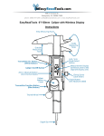
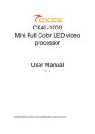
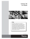
2 colors
PANTONE BLACK 7C
PANTONE 400 M
USER MANUAL
MEDIA TUBE RGB
Please check for the latest updates and changes on the TRAXON website.
© 2010 TRAXON TECHNOLOGIES ALL RIGHTS RESERVED.
WWW.TRAXONTECHNOLOGIES.COM
6/10 V0.2
1 colors
PANTONE BLACK 7C
CONTENTS
1. INTRODUCTION ..................................................................1
2. PACKING CONTENTS ........................................................2
3. SAFETY AND OPERATION .................................................3
4. MOUNTING .........................................................................4
5. SYSTEM CONFIGURATION ................................................5
5.1 TUBE RGB CONNECTION COMPONENTS ...................5
5.2 TUBE RGB CONNECTION ............................................6
5.3 LED CONTROL ............................................................6
6. CARE AND MAINTENANCE ...............................................9
7. TECHNICAL SPECIFICATION .............................................9
8. WARRANTY STATEMENT .................................................10
1 colors
PANTONE BLACK M
MEDIA TUBE RGB DIRECT VIEW
FOR YOUR OWN SAFETY AND THAT OF THE PRODUCT, PLEASE READ THIS USER
495mm/19.5” / 995mm/39.2” / 1495mm/58.9”
MANUAL CAREFULLY BEFORE BEGINNING SETUP AND INSTALLATION.
This is a class A product. In a domestic environment this product may cause radio
interference in which case the user may be required to take adequate measure.
15mm/0.6”
See
DETAIL A
140mm/5.5”
1. INTRODUCTION
140mm/5.5”
MEDIA TUBE RGB DIFFUSED
495mm/19.5” / 995mm/39.2” / 1495mm/58.9”
Length
TU.CR.0014000
TU.DR.0014001
495mm
TU.CR.0114000
TU.DR.0114001
995mm
TU.CR.0214000
TU.DR.0214001
1495mm
The Traxon Media Tube RGB is an IP66/IP67-rated slim LED tube for any wall or facade
media lighting. Available in 495mm, 995mm, and 1495mm lengths, the simple but
robust construction, allows up to 10m of tubes to be daisy chained on a single power
run.
DETAIL A
See
DETAIL B
The tube is controllable by DMX or e:pix (DVI capable) with auto-adddressing to the
next tube in the daisy chain.
The Media Tube RGB is housed in aluminium extrusion with clear silicon potting for
direct view or with a diffused PC cover.
Features:
DETAIL B
28.5mm/1.12”
28.5mm/1.12”
48.5mm/1.91”
MEDIA TUBE RGB DIFFUSED
28mm/1.10”
MEDIA TUBE RGB DIRECT VIEW
33mm/1.30”
33mm/1.30”
2. PACKING CONTENTS
• Available lengths: 495mm (20PXL), 995mm (40PXL), and 1495mm (60PXL)
• Direct View or Diffused
• DMX/e:pix Control
• Daisy Chain System
• Auto-Addressing
• SMART CHIP™ Technology
1
• Outdoor Applications (IP66/IP67-rated)
Media Tube RGB
2 x Mounting Bracket
2 x Screws
2
1 colors
PANTONE BLACK M
CONNECTING ANY CABLES AS THIS CAN DAMAGE THE PRODUCTS.
CAUTION – AVOID LOOKING DIRECTLY INTO THE LED LIGHT SOURCE AT CLOSE
RANGE FOR YOUR OWN SAFETY.
ANY PERSONS INSTALLING THIS PRODUCT SHOULD COMPLY WITH LOCAL
STANDARDS AND REGULATIONS AND MUST BE QUALIFIED FOR THE HANDLING
OF ELECTRICAL EQUIPMENT.
This product is designed for indoor and outdoor use.
Ensure product operates within the specified temperature range.
If the fixture has been subjected to drastic temperature variances, for example, following
transportation, do not connect the fixture until it has reached room temperature, as
moisture condensation may cause electric shock and product damages.
Plan your installation before mounting the Tube. The following should be considered for a
successful installation.
• Installation distances and choose appropriate cable lengths.
• Appropriate anchor bolts where necessary to secure the fixture.
• The number of fixtures and choose appropriate power sources.
• DMX/e:pix controller to be used to control the fixtures.
FIG 1 shows a typical mounting method of the Tube using screws.
FIG 1: Mounting the Tube
DIMENSION WITH MOUNTING BRACKET
75.5mm/2.97”
CAUTION – UNPLUG THE POWER SUPPLY FROM THE MAINS POWER BEFORE
4. MOUNTING
55mm/2.17”
3. SAFETY AND OPERATION
43.5mm/1.71”
43.5mm/1.71”
DIRECT VIEW
DIFFUSED
When installing the fixtures and system power supplies, please ensure they will not be
exposed to moisture and extreme heat (and direct sunlight for outdoor products).
Besides, keep a clean operating environment for the fixtures and system power supplies.
USE REAR STUDS FOR ALTERNATIVE MOUNTING
Please study this User Manual thoroughly and check the latest Technical Specification
Sheets available from our website [www.traxontechnologies.com] before setup.
M10 x 1.5P x 10mm
3
4
1 colors
PANTONE BLACK M
5. SYSTEM CONFIGURATION
5.2 MEDIA TUBE RGB CONNECTION
5.1 MEDIA TUBE RGB CONNECTION COMPONENTS
The Tubes are interconnected using the IN and OUT cables on each end of the tube.
Screw the connectors tightly for a water-tight seal. FIG 3 shows the Tube connections.
The Media Tube RGB is connected using a daisy chain system with power and data on
the same cable. FIG 2 shows some typical components for Media Tube RGB system.
See FIG 4 and FIG 5 for typical system wiring.
FIG 2: Connection Components for Media Tube RGB System
FIG 3: Tube RGB Connections
Indicates INPUT port
LED Engine 1000W 48V - single terminal
PS.IE.0011100
PSU Rack for LED Engine 1000W 48V
(Houses 3 x PS.IE.0011100)
PS.AC.0500100
IN
Starter Cable
End cap for OUT
connector of last tube.
Push in connectors and
screw tightly for a good seal.
LED Engine 1000W 48V - multi-terminal
PS.IE.0011000
PSU Rack for LED Engine 1000W 48V
(Houses 3 x PS.IE.0011000)
PS.AC.0500000
5.3 LED CONTROL
LED Engine 240W 48V Outdoor
PS.OB.0011000
Video Micro Converter
MC.PX.6000000
Pixel n
M12 Starter Cable (custom length)
Micro Server
CS.MA.5000000
M12 Power/Data Injector Cable
TU.AC.0000100
5
The LEDs on the Media Tube RGB are controlled by DMX/e:pix. Each pixel on the Tube
uses 3 channels, for R, G, and B. Pixel number 1 is at the end of the Tube near the IN
connector, and it uses the first three channels of the Tube. The Tube start address is
the next address from the previous tube in the daisy chain.
Connector End Cap M12
DO.AC.0000800
Control Channel Number
R
Tube start address + 3(n-1)
G
Tube start address + 3(n-1) + 1
B
Tube start address + 3(n-1) + 2
Pixel 1
Tube RGB 995
TU.DR.XXXXXXX
IN
Where: n is pixel number along the Tube.
(Pixel 1 is located at end, near the IN connector.)
6
7
DMX / e:pix
INDOOR
Ethernet
Source
100
AWG 8
150
200
250
TX Connect Data Cable
(DI.IC.xxxxxxx)
AWG14, 300mm
Installation engineer should use
appropriate plugs for outdoor connection.
AC 110V/220V 50/60Hz
SEE VMC SPECIFICATION FOR MORE INFORMATION
USE DVI SPLITTER FOR FURTHER VMC CHAINS
249-117
(End stopper)
281-309
(cover plate)
280-309
(cover plate)
Fuse:
6A slow blow
Ø5 x 20mm
FUSE
FUSE
FUSE
FUSE
FUSE
FUSE
279-901
279-901
281-611/281-417
218-611
WAGO® Part no.
DMX+
DMX–
48V DC
GND
CABLE C
PWR: AWG19
DATA: AWG24
Starter Cable
TUBE INTERCONNECTION
LED Tube configuration and installation.
TUBES ARE DAISY CHAINED
Injecting power for next daisy chain.
M12 Power/Data Injector Cable
TU.AC.0000100
Starter Cable (20m)
TU.AC.0000500
This wiring diagram shows only typical
connections. Actual wiring depends on
CABLE B
CABLE A
Interconnection Example:
®
WAGO terminal blocks on
35mm wide DIN rail.
Each power line can power 10
1m-length 40-LED tubes.
3x 1kW Rackmount PSU
can power up to 90
1m-length 40-LED tubes.
PSU Rack for LED Engine 1000W 48V
PS.AC.0500000
POWER/DATA INJECTION
Daisy-chained LED Tubes
Max. 400 LEDs
(e.g. 10x 1m 40-LED tubes)
Total 1200 DMX channels
30
10
20
30
40
50
10 x 1m tubes
18 x 0.5m tubes
9 x 1m tubes
6 x 1.5m tubes
CABLE B + CABLE C max. length: 100m
Cable A (AWG 16) Length (m)
0
5
10
15
20
25
60
Tube Starter Cable
POWER: AWG19
DATA: AWG24
CABLE C
White
CABLE A and CABLE C relationship
FUSE
FUSE
Black
Injecting power for next daisy chain.
M12 Power/Data Injector Cable
TU.AC.0000100
POWER/DATA INJECTION
TUBES ARE DAISY CHAINED
FUSE
FUSE
Daisy-chained LED Tubes
Max. 400 LEDs
(e.g. 10x 1m 40-LED tubes)
Total 1200 DMX channels
8611320000 (Weidmüller)
218-611
WAGO® Part no.
281-611/281-417
CAUTION: PLEASE ENSURE THAT THE POWER IS SWITCHED OFF WHEN THE
DATA CABLES ARE BEING CONNECTED. FAILURE TO DO SO WILL RESULT IN
DAMAGE TO THE PRODUCTS AND VOID THE PRODUCT WARRANTY.
CABLE B
CABLE A
Waterproof Junction Box
Blue
DMX–
Brown
GND
DMX+
48V DC
Tube Starter Cable
280-309
(cover plate)
(cover plate) 281-309
Terminal Block part numbers
CAUTION: PLEASE ENSURE THAT THE POWER IS SWITCHED OFF WHEN THE
DATA CABLES ARE BEING CONNECTED. FAILURE TO DO SO WILL RESULT IN
DAMAGE TO THE PRODUCTS AND VOID THE PRODUCT WARRANTY.
Pin 2: DMX+
Pin 1: DMX–
RJ45 Plug
Maximum 8 outputs.
Maximum 1536 channels per output.
CAT5 DATA CABLE (UTP AWG24)
DAISY-CHAINED VMCs
MAX. UNITS PER CHAIN: 8
PS.OB.0011000
300
AWG 8
AWG 10 AWG 10
Cable C (AWG 19) Length (m)
50
7x 1.5m tubes
10x 1m tubes
AWG 5
AWG 5
CABLE B + CABLE C max. length: 100m
0
5
10
15
20
25
30
CABLE A and CABLE C relationship
LED Engine 240W 48V
OUTDOOR
DVI OUT
DVI IN (DVI-D/DVI-I)
DVI OUT
DVI IN (DVI-D/DVI-I)
Video Micro Converter (VMC)
MC.PX.6000000
300mm
DVI
Source
Ethernet Switch
Video Control Server
CS.VS.0000100
BACK
Cable A (AWG 5/8/10) Length (m)
LED Engine 1000W 48V
PS.IE.0011000
FIG 4: Media Tube RGB System Connection Example 1
Cable C (AWG 19) Length (m)
Rackmount Power Supply Unit 3x 48V DC 1kW.
1 colors
PANTONE BLACK M
FIG 5: Media Tube RGB System Connection Example 2
8
1 colors
PANTONE BLACK M
6. CARE AND MAINTENANCE
Traxon™ products are of superior design and quality and should be treated with
care. The recommendations below will help fulfill and warranty obligations and
gain good use and longevity from the products.
- Do not attempt or use the product(s) until you read and understand the installation instructions.
Failure to adhere to these instructions could result in serious injury or property damage.
- Do not use product(s) if cables are damaged.
- Do not connect cables and connectors when wet or in wet area. Moisture on bare connectors can
cause electric shock and damage to product(s).
- Do not use product(s) in extreme heat environment. Ensure there is sufficient airflow and use cool
air circulation if required.
- Do not drop, knock, or shake product(s). Rough handling can damage the electronics and void the
warranty.
- Do not use harsh chemicals, cleaning solvents, or strong detergents to clean products. Wipe with
a damp cloth on housings and a dry cloth on electronics to remove dirt or dust.
- Do not attempt to service or repair the product(s) unless done by an authorized service personnel.
Contact your the local Traxon™ office or distributor for details.
If the product is not working correctly, please contact your nearest authorized service
centre or Traxon Technologies office for assistance.
As with all electronic devices, LED output degrades over time - a term called lumen
depreciation. This also explains why it is nearly impossible to expect photometric
performances of two LED products with different service life spans to be the same. The
rate of LED degradation is a complex function of many factors such as operating
efficiency, duration of continuous operation, and operating conditions (e.g. ambient
temperature).
Because LEDs are semiconductor devices, their performances are subject to inherent
variability commonly found in semiconductor industry. To improve consistency in
performance across the same product. LED manufacturers “sort” LEDs into bins
according to different preset parameters, such as forward driving voltage, illumination,
etc. Whereas binning is a sorting function, it is not a correction process. Inherent
variability in the manufacturing process results always in different binning distributions
according to different production lots. Traxon uses automatically binned LEDs on its
products, thereby minimizing output variations within the model range.
8. WARRANTY STATEMENT
Traxon warrants its Products against material or workmanship defects for a period of
two (2) years from date of purchase, provided that the purchased items are used under
the conditions stated in this user manual.
Please refer to the Product Warranty section under www.traxontechnologies.com/terms
for warranty terms and conditions.
7. TECHNICAL SPECIFICATION
Color Range:
Light Source:
Beam Angle:
Power Input*:
Power Consumption:
Weight:
Operating Temperature:
9
16.7 million additive RGB colors with variable intensity
20 / 40 / 60 Ultra Bright RGB SMD LED
120° (direct view)
48V DC
11W max. / 22W max. / 33W max.
0.8kg / 1.6kg / 2.3kg (direct view)
0.65kg / 1.3kg / 1.95kg (diffused)
–30°C to 50°C (–22°F to 122°F)
*For use with TRAXON LED Engine 1000W 48V (PS.IE.0011000/PS.IE.0011100), LED Engine 240W
48V Outdoor (PS.OB.0011000) power units.
10