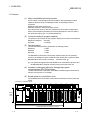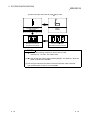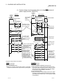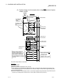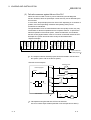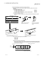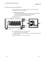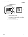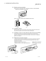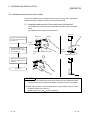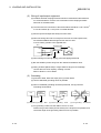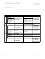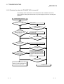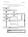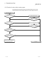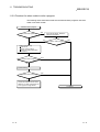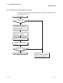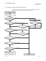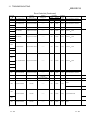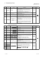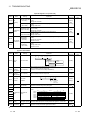
1
Basic Model QCPU(Q Mode) U User's Manual (Hardware Design,Maintenance and Inspection) Basic Model QCPU(Q Mode) User's Manual (Hardware Design, Maintenance and Inspection) SQCPU-(Q)-U-HH-E MODEL CODE 13JR43 Basic Model QCPU(Q Mode) User's Manual (Hardware Design, Maintenance and Inspection) MODEL SH(NA)-080187-A(0105)MEE HEAD OFFICE : MITSUBISHI DENKI BLDG MARUNOUCHI TOKYO 100-8310 TELEX : J24532 CABLE MELCO TOKYO NAGOYA WORKS : 1-14 , YADA-MINAMI 5 , HIGASHI-KU, NAGOYA , JAPAN When exported from Japan, this manual does not require application to the Ministry of Economy, Trade and Industry for service transaction permission. Specifications subject to change without notice. Mitsubishi Programmable Logic Controller Q00JCPU Q00CPU Q01CPU SAFETY PRECAUTIONS (Read these precautions before using.) When using Mitsubishi equipment, thoroughly read this manual and the associated manuals introduced in this manual. Also pay careful attention to safety and handle the module properly. These SAFETY PRECAUTIONS classify the safety precautions into two categories: "DANGER" and "CAUTION". DANGER Indicates that incorrect handling may cause hazardous conditions, resulting in death or severe injury. ! CAUTION Indicates that incorrect handling may cause hazardous conditions, resulting in medium or slight personal injury or physical damage. ! Depending on circumstances, procedures indicated by ! CAUTION may also be linked to serious results. In any case, it is important to follow the directions for usage. Store this manual in a safe place so that you can take it out and read it whenever necessary. Always forward it to the end user. [DESIGN PRECAUTIONS] ! DANGER Install a safety circuit external to the PLC that keeps the entire system safe even when there are problems with the external power supply or the PLC module. Otherwise, trouble could result from erroneous output or erroneous operation. (1) Outside the PLC, construct mechanical damage preventing interlock circuits such as emergency stop, protective circuits, positioning upper and lower limits switches and interlocking forward/reverse operations. (2) When the PLC detects the following problems, it will stop calculation and turn off all output in the case of (a). In the case of (b), it will stop calculation and hold or turn off all output according to the parameter setting. (a) The power supply module has over current protection equipment and over voltage protection equipment. (b) The PLC CPUs self-diagnostic functions, such as the watchdog timer error, detect problems. In addition, all output will be turned on when there are problems that the PLC CPU cannot detect, such as in the I/O controller. Build a fail safe circuit exterior to the PLC that will make sure the equipment operates safely at such times. See section 9.1 of this manual for example fail safe circuits. (3) Output could be left on or off when there is trouble in the outputs module relay or transistor. So build an external monitoring circuit that will monitor any single outputs that could cause serious trouble. A-1 A-1 [DESIGN PRECAUTIONS] ! DANGER When overcurrent which exceeds the rating or caused by short-circuited load flows in the output module for a long time, it may cause smoke or fire. To prevent this, configure an external safety circuit, such as fuse. Build a circuit that turns on the external power supply when the PLC main module power is turned on. If the external power supply is turned on first, it could result in erroneous output or erroneous operation. When there are communication problems with the data link, refer to the corresponding data link manual for the operating status of each station. Not doing so could result in erroneous output or erroneous operation. When connecting a peripheral device to the CPU module or connecting a personal computer or the like to the intelligent function module to exercise control (data change) on the running PLC, configure up an interlock circuit in the sequence program to ensure that the whole system will always operate safely. Also before exercising other control (program change, operating status change (status control)) on the running PLC, read the manual carefully and fully confirm safety. Especially for the above control on the remote PLC from an external device, an immediate action may not be taken for PLC trouble due to a data communication fault. In addition to configuring up the interlock circuit in the sequence program, corrective and other actions to be taken as a system for the occurrence of a data communication fault should be predetermined between the external device and PLC CPU. ! CAUTION Do not bunch the control wires or communication cables with the main circuit or power wires, or install them close to each other. They should be installed 100 mm (3.94 inch) or more from each other. Not doing so could result in noise that would cause erroneous operation. When controlling items like lamp load, heater or solenoid valve using an output module, large current (approximately ten times greater than that present in normal circumstances) may flow when the output is turned OFF to ON. Take measures such as replacing the module with one having sufficient rated current. A-2 A-2 [INSTALLATION PRECAUTIONS] ! CAUTION Use the PLC in an environment that meets the general specifications contained in this manual. Using this PLC in an environment outside the range of the general specifications could result in electric shock, fire, erroneous operation, and damage to or deterioration of the product. Hold down the module loading lever at the module bottom, and securely insert the module fixing hook into the fixing hole in the base unit. Incorrect loading of the module can cause a malfunction, failure or drop. When using the PLC in the environment of much vibration, tighten the module with a screw. Tighten the screw in the specified torque range. Undertightening can cause a drop, short circuit or malfunction. Overtightening can cause a drop, short circuit or malfunction due to damage to the screw or module. When installing extension cables, be sure that the connectors of base unit are installed correctly. After installation, check them for looseness. Poor connections could cause an input or output failure. Completely turn off the external power supply before loading or unloading the module. Not doing so could result in electric shock or damage to the product. Do not directly touch the module's conductive parts or electronic components. Touching the conductive parts could cause an operation failure or give damage to the module. [WIRING PRECAUTIONS] ! DANGER Completely turn off the external power supply when installing or placing wiring. Not completely turning off all power could result in electric shock or damage to the product. When turning on the power supply or operating the module after installation or wiring work, be sure that the module's terminal covers are correctly attached. Not attaching the terminal cover could result in electric shock. A-3 A-3 [WIRING PRECAUTIONS] ! CAUTION Be sure to ground the FG terminals and LG terminals to the protective ground conductor. Not doing so could result in electric shock or erroneous operation. When wiring in the PLC, be sure that it is done correctly by checking the product's rated voltage and the terminal layout. Connecting a power supply that is different from the rating or incorrectly wiring the product could result in fire or damage. External connections shall be crimped or pressure welded with the specified tools, or correctly soldered. Imperfect connections could result in short circuit, fires, or erroneous operation. Tighten the terminal screws with the specified torque. If the terminal screws are loose, it could result in short circuits, fire, or erroneous operation. Tightening the terminal screws too far may cause damages to the screws and/or the module, resulting in fallout, short circuits, or malfunction. Be sure there are no foreign substances such as sawdust or wiring debris inside the module. Such debris could cause fires, damage, or erroneous operation. The module has an ingress prevention label on its top to prevent foreign matter, such as wire offcuts, from entering the module during wiring. Do not peel this label during wiring. Before starting system operation, be sure to peel this label because of heat dissipation. [STARTUP AND MAINTENANCE PRECAUTIONS] ! DANGER Do not touch the terminals while power is on. Doing so could cause shock or erroneous operation. Correctly connect the battery. Also, do not charge, disassemble, heat, place in fire, short circuit, or solder the battery. Mishandling of battery can cause overheating or cracks which could result in injury and fires. Switch all phases of the external power supply off when cleaning the module or retightening the terminal or module mounting screws. Not doing so could result in electric shock. Undertightening of terminal screws can cause a short circuit or malfunction. Overtightening of screws can cause damages to the screws and/or the module, resulting in fallout, short circuits, or malfunction. A-4 A-4 [STARTUP AND MAINTENANCE PRECAUTIONS] ! DANGER The online operations conducted for the CPU module being operated, connecting the peripheral device (especially, when changing data or operation status), shall be conducted after the manual has been carefully read and a sufficient check of safety has been conducted. Operation mistakes could cause damage or problems with of the module. Do not disassemble or modify the modules. Doing so could cause trouble, erroneous operation, injury, or fire. Use any radio communication device such as a cellular phone or a PHS phone more than 25cm (9.85 inch) away from the PLC. Not doing so can cause a malfunction. Switch all phases of the external power supply off before mounting or removing the module. If you do not switch off the external power supply, it will cause failure or malfunction of the module. Do not drop or add an impact to the battery to be mounted in the module. Otherwise the battery will be broken, possibly causing internal leakage of electrolyte. Do not use but dispose of the battery if it has fallen or an impact is given to it. Before touching the module, always touch grounded metal, etc. to discharge static electricity from human body. Failure to do so can cause the module to fail or malfunction. [DISPOSAL PRECAUTIONS] ! CAUTION When disposing of this product, treat it as industrial waste. A-5 A-5 REVISIONS The manual number is given on the bottom left of the back cover. Print Date Aug., 2001 Oct., 2002 Jan., 2003 Manual Number Revision SH(NA)-080187-A First edition SH(NA)-080187-B Complete review Addition model Q32SB, Q33SB, Q35SB, Q64P, Q61SP SH(NA)-080187-C Addition Section 2.3, Section 2.3.1, Section 2.3.2, Section 2.4, Section 10.4, Section 10.5, APPENDIX 3, APPENDIX 3.1, APPENDIX 3.2, APPENDIX 3.3 Partial correction About Manuals, Chapter 1, Section 1.1, Section 2.1.1, Section 2.1.2, Section 2.2, Section 2.5, Section 4.1, Section 5.1.2, Section 7.1, Section 8.1.3, Section 10.3.1, Section 11.3.2, Section 11.6, Section 11.7, APPENDIX 1.2, APPENDIX 3.1, APPENDIX 3.2, APPENDIX 3.3 Japanese Manual Version SH-080186-D This manual confers no industrial property rights or any rights of any other kind, nor does it confer any patent licenses. Mitsubishi Electric Corporation cannot be held responsible for any problems involving industrial property rights which may occur as a result of using the contents noted in this manual. 2001 MITSUBISHI ELECTRIC CORPORATION A-6 A-6 INTRODUCTION Thank you for choosing the Mitsubishi MELSEC-Q Series of General Purpose Programmable Controllers. Please read this manual carefully so that equipment is used to its optimum. CONTENTS Safety Precautions .........................................................................................................................................A- 1 Revisions ........................................................................................................................................................A- 6 Contents .........................................................................................................................................................A- 7 About Manuals ...............................................................................................................................................A-14 How to Use This Manual................................................................................................................................A-15 About the Generic Terms and Abbreviations ................................................................................................A-16 Operating Precautions ...................................................................................................................................A-16 1 OVERVIEW 1- 1 to 1- 6 1.1 Features ................................................................................................................................................... 1- 4 2 SYSTEM CONFIGURATION 2- 1 to 2-15 2.1 System Configuration of Single CPU System......................................................................................... 2- 1 2.1.1 Q00JCPU .......................................................................................................................................... 2- 1 2.1.2 Q00CPU, Q01CPU ........................................................................................................................... 2- 3 2.1.3 Configuration for Use of GX Developer............................................................................................ 2- 7 2.2 Precautions for Use of Single CPU System............................................................................................ 2- 8 2.3 System Configuration of Multiple CPU System ...................................................................................... 2- 9 2.3.1 Q00CPU or Q01CPU........................................................................................................................ 2- 9 2.3.2 Configuration for Use of GX Developer............................................................................................ 2-13 2.4 Precautions for Use of Multiple CPU System ......................................................................................... 2-14 2.5 Confirming the Function Version. ............................................................................................................ 2-15 3 GENERAL SPECIFICATIONS 3- 1 to 3- 2 4 HARDWARE SPECIFICATION OF THE CPU MODULE 4- 1 to 4-10 4.1 Performance Specification....................................................................................................................... 4- 1 4.2 Part Names .............................................................................................................................................. 4- 4 4.2.1 Q00JCPU .......................................................................................................................................... 4- 4 4.2.2 Q00CPU, Q01CPU ........................................................................................................................... 4- 6 4.3 Switch Operation After Program Write .................................................................................................... 4- 8 4.4 Reset Operation ....................................................................................................................................... 4- 9 4.5 Latch Clear Operation.............................................................................................................................. 4-10 5 POWER SUPPLY MODULE 5- 1 to 5- 9 5.1 Specification ............................................................................................................................................. 55.1.1 Power supply module specifications ................................................................................................ 55.1.2 Selecting the power supply module.................................................................................................. 55.1.3 Precaution when connecting the uninterruptive power supply ........................................................ 5A-7 A-7 1 1 6 7 5.2 Part Names and Settings......................................................................................................................... 5- 8 6 BASE UNIT AND EXTENSION CABLE 6- 1 to 6-12 6.1 Base Unit Specification Table.................................................................................................................. 66.2 Extension Cable Specification Table....................................................................................................... 66.3 Parts Names of Base Unit ....................................................................................................................... 66.4 Setting the Extension Base Unit .............................................................................................................. 66.5 Guideline for Use of Extension Base Units (Q5!B)............................................................................... 67 BATTERY 1 3 4 7 9 7- 1 to 7- 2 7.1 Battery Specifications .............................................................................................................................. 7- 1 7.2 Installation of Battery................................................................................................................................ 7- 2 8 EMC AND LOW-VOLTAGE DIRECTIVES 8- 1 to 8-10 8.1 Requirements for conformance to the EMC Directive ............................................................................ 8- 1 8.1.1 Standards applicable to the EMC Directive ..................................................................................... 8- 1 8.1.2 Installation instructions for the EMC Directive ................................................................................. 8- 2 8.1.3 Cables................................................................................................................................................ 8- 3 8.1.4 Power supply module, Q00JCPU power supply section ................................................................. 8- 7 8.1.5 Others ................................................................................................................................................ 8- 7 8.2 Requirement to Conform to the Low-Voltage Directive .......................................................................... 8- 8 8.2.1 Standard applied for MELSEC-Q series PLC .................................................................................. 8- 8 8.2.2 MELSEC-Q series PLC selection..................................................................................................... 8- 8 8.2.3 Power supply..................................................................................................................................... 8- 9 8.2.4 Control box ........................................................................................................................................ 8- 9 8.2.5 Grounding.......................................................................................................................................... 8-10 8.2.6 External wiring................................................................................................................................... 8-10 9 LOADING AND INSTALLATION 9- 1 to 9-24 9.1 General Safety Requirements ................................................................................................................. 9- 1 9.2 Calculating Heat Generation by PLC ...................................................................................................... 9- 6 9.3 Module Installation ................................................................................................................................... 9- 9 9.3.1 Precaution on installation.................................................................................................................. 9- 9 9.3.2 Instructions for mounting the base unit ............................................................................................ 9-12 9.3.3 Installation and removal of the module............................................................................................. 9-15 9.4 Setting the Stage Number of the Extension Base Unit........................................................................... 9-17 9.5 Connection and Disconnection of the Extension Cable ......................................................................... 9-18 9.6 Wiring........................................................................................................................................................ 9-21 9.6.1 The precautions on the wiring........................................................................................................... 9-21 9.6.2 Connecting to the power supply module .......................................................................................... 9-24 10 MAINTENANCE AND INSPECTION 10- 1 to 10- 8 10.1 Daily Inspection.................................................................................................................................... 10- 2 10.2 Periodic Inspection............................................................................................................................... 10- 3 10.3 Battery Replacement ........................................................................................................................... 10- 4 A-8 A-8 10.3.1 Battery service life......................................................................................................................... 10- 5 10.3.2 Battery replacement procedure .................................................................................................... 10- 6 10.4 When Resuming Operation after Storage of PLC without Battery ................................................... 10- 7 10.5 When Resuming PLC Operation after Storage of PLC with Battery Gone Flat ............................... 10- 8 11 TROUBLESHOOTING 11- 1 to 11-49 11.1 Troubleshooting Basics ....................................................................................................................... 11- 1 11.2 Troubleshooting ................................................................................................................................... 11- 2 11.2.1 Troubleshooting flowchart............................................................................................................. 11- 2 11.2.2 Flowchart for when the "POWER" LED is turned off ................................................................... 11- 3 11.2.3 Flowchart for when the "RUN" LED is turned off ......................................................................... 11- 4 11.2.4 When the "RUN" LED is flashing.................................................................................................. 11- 5 11.2.5 Flowchart for when the "ERR." LED is on/flashing ...................................................................... 11- 5 11.2.6 Flowchart for when output module LED is not turned on ............................................................ 11- 6 11.2.7 Flowchart for when output load of output module does not turn on ............................................ 11- 7 11.2.8 Flowchart for when unable to read a program ............................................................................. 11- 8 11.2.9 Flowchart for when unable to write a program............................................................................. 11- 9 11.2.10 Flowchart for when program is rewritten.................................................................................... 11-10 11.2.11 Flowchart for when UNIT VERIFY ERR. occurs........................................................................ 11-11 11.2.12 Flowchart for when CONTROL BUS ERR. occurs.................................................................... 11-12 11.3 Error Code List ..................................................................................................................................... 11-13 11.3.1 Procedure for reading error codes ............................................................................................... 11-13 11.3.2 Error code list ................................................................................................................................ 11-14 11.4 Canceling of Errors .............................................................................................................................. 11-28 11.5 Input/Output Module Troubleshooting................................................................................................. 11-29 11.5.1 Input circuit troubleshooting.......................................................................................................... 11-29 11.5.2 Output circuit troubleshooting....................................................................................................... 11-32 11.6 Special Relay List................................................................................................................................. 11-33 11.7 Special Register List ............................................................................................................................ 11-38 APPENDICES App- 1 to App-16 APPENDIX 1 Error Code Return to Origin During General Data Processing..........................................App- 1 APPENDIX 1.1 Error code overall explanation .....................................................................................App- 1 APPENDIX 1.2 Description of the errors of the error codes (4000H to 4FFFH) ...................................App- 2 APPENDIX 2 External Dimensions ...........................................................................................................App- 6 APPENDIX 2.1 CPU module .................................................................................................................App- 6 APPENDIX 2.2 Power supply module...................................................................................................App- 7 APPENDIX 2.3 Main base unit ..............................................................................................................App- 9 APPENDIX 2.4 Slim type main base unit ..............................................................................................App-11 APPENDIX 2.5 Extension base unit ......................................................................................................App-12 APPENDIX 3 Functions Improvement of Basic Model QCPU .................................................................App-14 APPENDIX 3.1 Specification comparison .............................................................................................App-14 APPENDIX 3.2 Additional functions ......................................................................................................App-14 APPENDIX 3.3 Usability of additional functions by GX Developer version .........................................App-15 INDEX A-9 Index- 1 to Index- 2 A-9 (Related manual)...........................................................................Basic model QCPU (Q Mode) User's Manual (Function Explanation, Program Fundamentals) CONTENTS 1 OVERVIEW 1.1 Features 1.2 Program Storage and Calculation 1.3 Convenient Programming Devices and Instructions 2. SYSTEM CONFIGURATION 2.1 System Configuration 2.1.1 Q00JCPU 2.1.2 Q00CPU,Q01CPU 2.1.3 Configuration of GX Developer 2.2 Precaution on System Configuration 2.3 Confirming the function version 3 PERFORMANCE SPECIFICATION 4 SEQUENCE PROGRAM CONFIGURATION & EXECUTION CONDITIONS 4.1 Sequence Program 4.1.1 Main routine program 4.1.2 Sub-routine programs 4.1.3 Interrupt programs 4.2 Concept of Scan Time 4.3 Operation Processing 4.3.1 Initial processing 4.3.2 I/O refresh (I/O module refresh processing) 4.3.3 Automatic refresh of the intelligent function module 4.3.4 END processing 4.4 RUN, STOP, PAUSE Operation Processing A - 10 A - 10 4.5 Operation Processing during Momentary Power Failure 4.6 Data Clear Processing 4.7 Input/Output Processing and Response Lag 4.7.1 Refresh mode 4.7.2 Direct mode 4.8 Numeric Values which Can Be Used in Sequence Program 4.8.1 BIN (Binary Code) 4.8.2 HEX (Hexadecimal) 4.8.3 BCD (Binary Coded Decimal) 4.8.4 Real number (floating-point data) 4.9 Character String Data 5 ASSIGNMENT OF I/O NUMBERS 5.1 Relationship Between the Number of Stages and Slots of the Expansion Base Unit 5.1.1 Q00JCPU 5.1.2 Q00CPU/QO1CPU 5.2 Installing Extension Base Units and Setting the Number of Stages 5.3 Base Unit Assignment (Base Mode) 5.4 What are I/O Numbers? 5.5 Concept of I/O Number Assignment 5.5.1 I/O numbers of main base unit,slim type main base unit and extension base unit 5.5.2 Remote station I/O number 5.6 I/O Assignment by GX Developer 5.6.1 Purpose of I/O assignment by GX Developer 5.6.2 Concept of I/O assignment using GX Developer 5.7 Examples of I/O Number Assignment 5.8 Checking the I/O Numbers 6 ABOUT MEMORY AND FILES HANDLED BY BASIC MODEL QCPU 6.1 About Basic model QCPU's Memory 6.2 About Program Memory 6.3 About Standard ROM 6.4 Executing Standard ROM Program (Boot Run) and Writing Program Memory to ROM 6.4.1 Executing Standard ROM Program 6.4.2 Write program memory to ROM 6.5 About Standard RAM 6.6 Program File Configuration 6.7 GX Developer File Operation and File Handling Precautions 6.7.1 File operation 6.7.2 File handling precautions 6.7.3 File capacity A - 11 A - 11 7 FUNCTION 7.1 Function List 7.2 Constant Scan 7.3 Latch Functions 7.4 Setting the Output (Y) Status when Changing from STOP Status to RUN Status 7.5 Clock Function 7.6 Remote Operation 7.6.1 Remote RUN/STOP 7.6.2 Remote PAUSE 7.6.3 Remote RESET 7.6.4 Remote Latch Clear 7.6.5 Relationship of the remote operation and Basic model QCPU RUN/STOP switch 7.7 Selection of Module Input Response Time (I/O Response Time) 7.7.1 Selection of input response time of the input module/composite I/O module 7.7.2 Selection of input response time of the high-speed input module 7.7.3 Selection of input response time of the interrupt module 7.8 Error-time Output Mode 7.9 Hardware Error-time CPU Operation Mode Setting 7.10 Setting the Switches of the Intelligent-Function Module 7.11 Program Write during RUN of Basic Model QCPU 7.11.1 Writing Data in the Ladder Mode during the RUN Status 7.12 Multiple-User Debugging Function 7.12.1 Multiple-user monitoring function 7.12.2 Multiple-user simultaneous write during RUN 7.13 Watchdog Timer (WDT) 7.14 Self-Diagnosis Function 7.14.1 LED display when error occurs 7.14.2 Cancel error 7.15 Failure History 7.16 System Protect 7.16.1 Password registration 7.16.2 Remote password 7.17 GX Developer system monitor 7.18 LED Display 7.19 Serial Communication Function (Usable with the Q00CPU or Q01CPU) 8 COMMUNICATION WITH INTELLIGENT FUNCTION MODULE 8.1 Communication Between Basic model QCPU and Q-series Intelligent Function Modules 8.1.1 Initial setting and automatic refresh setting using GX Configurator 8.1.2 Communication using device initial values 8.1.3 Communication using FROM/TO instructions 8.1.4 Communication Using The Intelligent Function Module Device 8.1.5 Communication Using The Instructions Dedicated for Intelligent Function Modules 8.2 Request of Intelligent Function Module to Basic Model QCPU 8.2.1 Interrupt from intelligent function module A - 12 A - 12 9. PARAMETER LIST 10 DEVICES 10.1 Device List 10.2 Internal User Devices 10.2.1 Inputs (X) 10.2.2 Outputs (Y) 10.2.3 Internal relays (M) 10.2.4 Latch relays (L) 10.2.5 Anunciators (F) 10.2.6 Edge relay (V) 10.2.7 Link relays (B) 10.2.8 Special link relays (SB) 10.2.9 Step relays (S) 10.2.10 Timers (T) 10.2.11 Counters (C) 10.2.12 Data registers (D) 10.2.13 Link registers (W) 10.2.14 Special link registers (SW) 10.3 Internal System Devices 10.3.1 Function devices (FX, FY, FD) 10.3.2 Special relays (SM) 10.3.3 Special registers (SD) 10.4 Link Direct Devices (J \ ) 10.5 Intelligent Function Module Devices (U \G ) 10.6 Index Registers (Z) 10.6.1 Switching between main routine/sub-routine program and interrupt program 10.7 File Registers (R) 10.8 Nesting (N) 10.9 Pointers 10.10 Interrupt Pointers (I) 10.11 Other Devices 10.11.1 SFC block device (BL) 10.11.2 Network No. designation device (J) 10.11.3 I/O No. designation device (U) 10.11.4 Macro instruction argument device (VD) 10.12 Constants 10.12.1 Decimal constants (K) 10.12.2 Hexadecimal constants (H) 10.12.3 Real number (E) 10.12.4 Character string ( " " ) 10.13 Useful Method of Using the Devices 10.13.1 Device initial value A - 13 A - 13 11 PROCESSING TIMES OF THE BASIC MODEL QCPU 11.1 Scan Time Structure 11.2 Concept of Scan Time 11.3 Other Processing Times 12 PROCEDURE FOR WRITING PROGRAMS TO BASIC MODEL QCPU 12.1 Items to Consider when Creating Program 12.2 Procedure for writing program to the Basic model QCPU 13 OUTLINE OF MULTIPLE CPU SYSTEMS 13.1 Features 13.2 Outline of Multiple CPU Systems 13.3 Differences with Single CPU Systems 14 SYSTEM CONFIGURATION OF MULTIPLE CPU SYSTEM 14.1 System Configuration 14.2 Precautions For Multiple CPU System Configuration 14.2.1 Function versions of Basic model QCPU, Motion CPU and PC CPU module that can be used, and their mounting positions 14.2.2 Precautions when using Q Series I/O modules and intelligent function modules 14.2.3 Modules that have mounting restrictions 14.2.4 Compatible GX Developers and GX Configurators 14.2.5 Parameters that enable the use of Multiple CPU System 14.2.6 Resetting the Multiple CPU System 14.2.7 Processing when stop errors occur 14.2.8 Reducing the time required for Multiple CPU System processing 15 ALLOCATING MULTIPLE CPU SYSTEM I/O NUMBERS 15.1 Concept behind Allocating I/O Numbers 15.1.1 I/O modules and Intelligent function module I/O numbers 15.1.2 I /O number of Basic model QCPU, Motion CPU and PC CPU module 15.2 Setting of Control CPUs with GX Developer 16 COMMUNICATION BETWEEN CPU MODULES IN MULTIPLE CPU SYSTEM 16.1 Automatic Refresh of CPU Shared Memory 16.2 Communication with Multiple CPU Instructions and Intelligent Function Module Devices 16.3 Interactive Communications between The Basic model QCPU and Motion CPU 16.3.1 Control commands from the Basic model QCPU to the Motion CPU (Motion dedicated instructions) 16.3.2 Reading and writing device data(Between Multiple CPU communication dedicated instructions) 16.4 CPU Shared Memory A - 14 A - 14 17 COMMUNICATIONS BETWEEN THE MULTIPLE CPU SYSTEM'S I/O MODULES AND INTELLIGENT FUNCTION MODULES 17.1 Range of Control CPU Communications 17.2 Range of Non-control CPU Communications 18 PROCESSING TIME FOR MULTIPLE CPU SYSTEM BASIC MODEL QCPUs 18.1 Concept behind Scan Time 18.2 Factor to Prolong the Scan Time 19 STARTING UP THE MULTIPLE CPU SYSTEM 19.1 Flow-chart for Starting Up the Multiple CPU System 19.2 Setting Up the Multiple CPU System Parameters (Multiple CPU Settings, Control CPU Settings) 19.2.1 System configuration 19.2.2 Creating new systems 19.2.3 Using existing preset Multiple CPU settings and I/O allocations APPENDICES APPENDIX 1 Special Relay List APPENDIX 2 Special Register List APPENDIX 3 List of Interrupt Pointer Nos. and Interrupt Factors APPENDIX 4 Enhancement of the Basic Model QCPU Functions APPENDIX 4.1 Specification Comparison APPENDIX 4.2 Added Functions INDEX A - 15 A - 15 About Manuals The following manuals are related to this product. Referring to this list, please request the necessary manuals. Related Manuals Manual Number (Model Code) Manual Name Basic model QCPU (Q Mode) User's Manual (Function Explanation, Program Fundamentals) This manual explains the functions, programming methods, devices and so on necessary to create programs with the Basic model QCPU. SH-080188 (13JR44) (Sold separately) QCPU (Q Mode)/QnACPU Programming Manual (Common Instructions) This manual describes how to use the sequence instructions, basic instructions and application instructions. SH-080039 (13JF58) (Sold separately) Q Corresponding MELSEC Communication Protocol Reference Manual This manual explains how the external devices read and write PLC CPU data through communication with the MC protocol using the serial communication module/Ethernet module. SH-080008 (13JF89) (Sold separately) QCPU (Q Mode)/QnACPU Programming Manual (PID Control Instructions) SH-080040 (13JF59) This manual describes the dedicated instructions used for PID control. (Sold separately) QCPU (Q Mode)/QnACPU Programming Manual (SFC) This manual explains the system configuration, performance specifications, functions, programming, debugging and error codes of MELSAP3. SH-080041 (13JF60) (Sold separately) QCPU (Q Mode) Programming Manual (MELSAP-L) This manual describes the programming methods, specifications and functions that are necessary to create the MELSAP-L type SFC programs. SH-080076 (13JF61) (Sold separately) QCPU (Q Mode) Programming Manual (Structured Text) SH-080366E (13JF68) This manual describes the structured text language programming methods. (Sold separately) A - 16 A - 16 How to Use This Manual This manual is prepared for users to understand the hardware specifications of the modules such as CPU modules, power supply modules, base units and similar, maintenance and inspections of the system, and troubleshooting required when you use MELSEC-Q series PLCs. The manual is classified roughly into three sections as shown below. 1) Chapters 1 and 2 Describe the outline of the CPU module and the system configuration. The basics of the system configuration of CPU module are described. 2) Chapters 3 to 7 Describe the general specifications indicating the operating environments of the CPU module, power supply module, base units, and the performance specifications of these modules. 3) Chapters 8 to 11 Describe the overall maintenance such as the installation of the CPU module, daily inspections, and troubleshooting. REMARK This manual does not explain the functions of the CPU module. For these functions, refer to the manual shown below. • Basic model QCPU (Q Mode) User's Manual (Function Explanation, Program Fundamentals) A - 17 A - 17 About the Generic Terms and Abbreviations In this manual, the following general names and abbreviations are used for explanation of basic model QCPU unless otherwise specified. Generic Term/Abbreviation Basic model QCPU CPU Q Series Description General name for Q00JCPU, Q00CPU and Q01CPU modules. Abbreviation for Mitsubishi MELSEC-Q Series PLC. Product name of GPP function software package SW D5C-GPPW-E(-EV) compatible with Q Series GX Developer Abbreviation for GX Developer of Version 7 or later. Use Version "8" when using the functions of the function version B. General name for Q33B, Q35B, Q38B, Q312B type main base unit with Q00CPU, Q01CPU, Q Series power supply module, input/output module and intelligent function Q3 B module attachable. 1 General name for Q32SB, Q33SB, and Q35SB slim type main base units to which the following modules can be installed: Q00CPU, Q01CPU, slim type power supply Q3 SB module, input/output module, intelligent function module 1 General name for Q52B and Q55B type extension base unit with Q series input/output Q5 B module and intelligent function module attachable. General name for Q63B, Q65B, Q68B and Q612B type extension base unit with Q Q6 B Series power supply module, input/output module and intelligent function module attachable. General name for Q33B, Q35B, Q38B, and Q312B type main base unit to which the following modules can be installed: Q00CPU, Q01CPU, Q-series power supply module, Main base unit input/output module, intelligent function module, and Q00JCPU (base unit). 1 General name for Q32SB, Q33SB, and Q35SB slim type main base unit to which the following modules can be installed: Q00CPU, Q01CPU, slim type power supply Slim type main base unit module, input/output module and intelligent function module. 1 Extension base unit General name for Q5 B and Q6 B. Base unit General name for main base unit, slim type main base unit, and extension base unit General name for QC05B, QC06B, QC12B, QC30B, QC50B, QC100B type extension Extension cable cable. General name for Q61P-A1, Q61P-A2, Q62P, Q63P and Q64P types power supply Power supply module module. Slim type power supply module General name for Q61SP slim type power supply module Battery General name for battery for Q6BAT type CPU module. 1: In a multiple CPU system configuration, the motion CPU and PC CPU module are also mountable. Operating Precautions Precautions for using the Basic model QCPU for the first time (1) When using the Basic model QCPU for the first time, the user memories must be formatted using GX Developer. Refer to "6 ABOUT MEMORIES AND FILES HANDLED BY BASIC MODEL QCPU" in the Basic Model QCPU User's Manual (Function Explanation/Program Fundamentals). When using GX Developer for formatting, refer to the GX Developer manual. Precautions for the battery (1) Operation after storing PLC without battery When starting the PLC operation after being stored with the Basic model QCPU battery removed, the user memories must be formatted using GX Developer. (Refer to Section 10.4.) (2) When battery has gone flat during storage of PLC When the Basic model QCPU battery has gone flat during storage of the PLC, the user memories must be formatted using GX Developer. (Refer to Section 10.5.) A - 18 A - 18 1 OVERVIEW MELSEC-Q 1 OVERVIEW This manual describes the hardware specification and handling method of the basic model QCPU. It also describes the specifications of the power supply modules, base units, extension cables and battery. Refer to the following functions for details on power supply modules, base units, extension cables, battery specifications and other information. Basic Model QCPU (Q mode) User's Manual (Hardware Design, Maintenance and Inspections) (1) Q00JCPU • The Q00JCPU is a CPU module consisting of a CPU module, a power supply module and a main base unit (five slots). • This CPU allows connection of up to two extension base units to accept up to 16 input/output and intelligent function modules. • The number of input/output points controllable by the main and extension base units is 256. When a CC-Link/LT module is used, 1024 points can be controlled by a single module. (2) Q00CPU, Q01CPU • Q00CPU and Q01CPU are stand alone CPU units that are installed in the main base unit or slim type main base unit. • Up to four stages of extension base units can be connected and maximum 24 pieces of the input/output modules, intelligent function modules and other modules can be installed. However, the slim type main base unit are not compatible with extension base unit. • The main base unit, slim type main base unit or extension base unit can control up to 1024 input/output points. When a CC-Link/LT module is used, 1024 points can be controlled by a single module. • The Basic model QCPU can be used with the motion CPU and PC CPU module to configure a multiple PLC system. For detailed explanation of the multiple PLC system, refer to the Basic Model QCPU User's Manual (Function Explanation/Program Fundamentals) (SH080188). 1-1 1-1 1 1 OVERVIEW MELSEC-Q The Basic model QCPU is updated to add functions. The added functions can be judged by the function version/serial No. of the CPU module. Table 1.1 indicates the added functions and the GX Developer version compatible with the additional functions. When using any of the added functions, confirm the function version/serial No. and GX Developer version. 1 Table 1.1 List of Functions Added to Basic Model QCPU and Function Version/Serial No. Compatible Updates of Basic Model QCPU Function version Serial No. B 04122 or later GX Developer Additional functions • Multiple PLC system (Q00CPU, Q01CPU) Version 8 • SFC or later • Function block • Structured text (ST) • Real number operation function • PID operation function 1 • Remote password setting • Increased standard RAM capacity (Q00CPU, Q01CPU) 1 • Device initial value automatic setting • Interrupt function from intelligent function module • Online program correction function using pointer 1: Functions irrelevant to GX Developer POINT Refer to Section 2.3 for the confirmation of the function version and serial No. of the Basic model QCPU. 1-2 1-2 1 OVERVIEW MELSEC-Q The following table indicates differences between the Basic model QCPU. Item CPU module Main base Main base unit unit Slim type main base unit Extension base unit Number of extension stages Number of input/output modules to be installed Power supply module Main base unit Slim type main base unit Extension Q52B, Q55B base unit Q63B, Q65B, Q68B, Q612B Extension cable Memory card interface RS-232 External interface USB Processing speed LD X0 (Sequence instruction) MOV D0 D1 Program capacity Program memory Memory Standard RAM capacity Standard ROM CPU shared memory 3 Device memory capacity Number of input/output devices points (Remote I/O is contained.) Number of input/output points File register Serial communication function 1-3 Q00JCPU Q00CPU Q01CPU CPU module, Power supply module, Main base unit Stand-alone CPU module (5 slots) Integrated type Unnecessary Necessary (Q33B, Q35B, Q38B, Q312B) Unnecessary Necessary (Q32SB, Q33SB, Q35SB) Connectable (Q52B, Q55B, Q63B, Q65B, Q68B, Q612B) Up to 2 stages Up to 4 stages 16 modules 24 modules Unnecessary Unnecessary Necessary Necessary Unnecessary Necessary QC05B, QC06B, QC12B, QC30B, QC50B, QC100B No Yes (transmission rate: 9.6kbps, 19.2kbps, 38.4kbps, 57.6kbps, 115.2kbps) No 0.20µs 0.16µs 0.10µs 0.70µs 0.56µs 0.35µs 8k steps (32 kbyte) 8k steps (32 kbyte) 14k steps (56 kbyte) 58 kbyte 94 kbyte —— 128 kbyte 2 58 kbyte 94 kbyte None 1k bytes (user free area 320 words) The number of device points can be changed within the range of 16.4k words. 2048 points 256 points No No 1024 points Yes (64k points fixed) Yes (using the RS-232 interface of the CPU module) 1: 1 step of the program capacity is 4 bytes. 2: 64k bytes for the function version A. 3: Memory added to the function version B. The CPU shared memory is not latched. The CPU shared memory is cleared when the PLC is powered on or the CPU module is reset. 1-3 1 OVERVIEW MELSEC-Q 1.1 Features (1) Many controllable input/output points As the number of input/output points accessible to the input/output modules loaded on the base units, the following number of input/output points is supported. Q00JCPU: 256 points (X/Y0 to FF) Q00CPU, Q01CPU: 1024 points (X/Y0 to 3FF) Up to 2048 points (X/Y0 to 7FF) are supported as the number of input/output device points usable for refreshing the remote input/output of CC-Link and the link inputs and outputs (LX, LY) of MELSECNET/H. (2) Lineup according to program capacity The optimum CPU module for the program capacity to be used can be selected. Q00JCPU, Q00CPU : 8k steps Q01CPU : 14k steps (3) Fast processing The LD instruction processing speeds are the following values. Q00JCPU : 0.20µs Q00CPU : 0.16µs Q01CPU : 0.10µs The MELSEC-Q series base unit and high-speed system bus can speed up access to an intelligent function module and link refresh with a network module. MELSECNET/H link refresh processing : 2.2ms/2k words 1 1 This speed only applies when the SB/SW is not used with the Q01CPU and the MELSECNET/H network module is used as the main base unit. (4) Increase in debugging efficiency through high-speed communication with GX Developer The RS-232 interface of the Basic model QCPU enables program write/read or monitor at a maximum of 115.2kbps. (5) Saved space by a reduction in size The installation area of the Basic model QCPU is about 60% of that of the AnS series. Comparison of installation space 1SX10 1SY50 1SX41 1SY41 1SX81 1SY81 1SX42 1SY42 98mm (3.86 inch) 5 Slot Main Base Unit 245mm(9.65inch) (depth:98mm(3.86inch)) 8 Slot Main Base Unit 328mm(12.92inch) 12 Slot Main Base Unit 439mm(17.30inch) 1-4 1-4 1 OVERVIEW MELSEC-Q (6) Connection of up to four/two extension base units (a) The Q00JCPU can connect up to two extension base units (three base units including the main) and accepts up to 16 modules. (b) The Q00CPU, Q01CPU can connect up to four extension base units (five base units including the main) and accepts up to 24 modules. (c) The overall distance of the extension cables is up to 13.2m to ensure high degree of extension base unit arrangement. POINT (1) When connected with a bus, the GOT uses one of the above extension units. Therefore, the number of connectable extension base units decreases by one. (2) No extension base unit can be connected if the slim type main base unit (Q3 SB) is used. (7) Serial communication function for communication with personal computer or display device With the RS-232 interface of the Q00CPU or Q01CPU connected with a personal computer, display device or the like, the MELSEC communication protocol (hereafter refered to as the MC protocol) can be used to make communication. RS-232 cable Personal computer, display device Communication in MC protocol The serial communication function only allows communication in the MC protocol (QnA-compatible 3C frame (format 4), QnA-compatible 4C frame (format 4, 5)). The serial communication function does not allow communication in the nonprocedure protocol or bidirectional protocol. Refer to the following manual for the MC protocol. • Q Corresponding MELSEC Communication Protocol Reference Manual (8) Built-in standard ROM The flash ROM for storing parameters and sequential program is installed as a standard feature for easier protection of important program. (9) Blocking an invalid access using the file password Use of the file password allows the setting of the access level (read disable, write disable) of a program to prevent program changes from being made by illegal access. 1-5 1-5 1 OVERVIEW MELSEC-Q (10) 64k points of file registers (Q00CPU, Q01CPU) The standard RAM capacity has been increased from 64k bytes to 128k bytes to double the file register capacity (64k points). The increase of battery-backed data provides allowances for control programs. (11) Remote password setting When external access is made to an Ethernet module, serial communication module or modem interface module, whether access to the Basic model QCPU may be made or not can be selected using a remote password. (12) Multiple CPU system compatibility A multiple CPU system can be configured by the Basic model QCPU (Q00CPU, Q01CPU only), motion CPU and PC CPU module. REMARK • The features in (10) to (12) are functions added to the Basic model CPU whose first five digits of serial No. are 04122 or later. • The remote password function can be executed when the Ethernet module, serial communication module or modem interface module of function version B is used with GX Developer 8 or later. 1-6 1-6 2 SYSTEM CONFIGURATION MELSEC-Q 2 SYSTEM CONFIGURATION This section describes the system configuration of the Basic model QCPU, cautions on use of the system, and configured equipment. 2.1 System Configuration of Single CPU System 2 2.1.1 Q00JCPU This section explains the equipment configuration of a Q00JCPU system and the outline of the system configuration. (1) Equipment configuration MITSUBISHI LITHIUM BATTERY Battery (Q6BAT) Basic model QCPU (Q00JCPU) Input/output module/ Intelligent function module Q5 B extension base unit (Q52B, Q55B) Extension cable (QC05B, QC06B, QC12B, QC30B, QC50B, QC100B) Q6 B extension base unit (Q63B, Q65B, Q68B, Q612B) Input/output module/ Intelligent function module 2-1 Power supply module/ Input/output module/ Intelligent function module 2-1 2 SYSTEM CONFIGURATION MELSEC-Q (2) Outline of system configuration (b) System including extension base unit and GOT (a) System including extension base units Slot number 0F 1F 2F 3F 4F O IU NT System configuration O U T 00 10 20 30 40 0F 1F 2F 3F 4F Extension base unit (Q68B) 5 6 7 8 9 10 11 12 Extension 1 50 60 70 80 90 A0 B0 C0 O IU NT 5F 6F 7F 8F 9F AF BF CF CPU module Extension cable Extension base unit (Q68B) 5 6 7 8 9 10 11 12 Extension 1 0 1 2 3 4 Power supply module 2 O U T Power supply module Extension cable CPU module 0 1 2 3 4 00 10 20 30 40 50 60 70 80 90 A0 B0 C0 5F 6F 7F 8F 9F AF BF CF Extension base unit (Q65B) Extension 2 D0 E0 F0 DF EF FF Inhibited Inhibited Power supply module 13 14 15 O IU NT Number of extension units: 2 Slot No. :0 Loading will cause error Extension cable connector Both of the above systems assume that each slot of the main and extension base units is loaded with a 16-point module. Maximum number of Extension Stages Maximum number of input/output modules to be installed Maximum number of input/output points Main base unit Extension base unit Extension cable Notes Two Extension Stages 16 modules 256 1 Unnecessary Q52B, Q55B, Q63B, Q65B, Q68B, Q612B QC05B, QC06B, QC12B, QC30B, QC50B, QC100B (1) Do not use an extension cable longer than an overall extension length of 13.2m(43.31ft.). (2) When using an extension cable, do not bind it together with the main circuit (high voltage and heavy current) line or do not lay down them closely to each other. (3) When setting the No. of the expansion stages, set it in the ascending order so that the same No. is not set simultaneously by two extension base units. (4) The QA1S6 B/QA65B cannot be connected as an extension base unit. (5) Connect the extension cable from OUT of the extension cable connector of the base unit to IN of the extension base unit on the next stage. (6) If 17 or more modules are installed, an error will occur. (7) When bus-connected, the GOT occupies one extension stage and one slot. (8) The Q00JCPU processes the GOT as a 16-point intelligent function module. Hence, connection of one GOT decreases the number of controllable points on base units by 16 points. (9) The bus extension connector box (A9GT-QCNB) cannot be connected to the Q00JCPU. It should be connected to the extension base unit. 1 : Indicates the maximum number of I/O points of the CPU module and does not indicate the maximum number of I/O points of the system. When a CC-Link/LT module is used, 1024 points can be controlled per module. 2-2 2-2 2 SYSTEM CONFIGURATION MELSEC-Q 2.1.2 Q00CPU, Q01CPU This section explains the equipment configuration of a Q00CPU, Q01CPU system and the outline of the system configuration. (1) Equipment configuration (a) When the main base unit (Q3 B) is used MITSUBISHI LITHIUM BATTERY Q5 B extension base unit (Q52B, Q55B) Input/output module/ Intelligent function module Basic model QCPU (Q00CPU, Q01CPU) Battery (Q6BAT) Main base unit (Q33B, Q35B, Q38B, Q312B) Power supply module/ Input/output module/ Intelligent function module Extension cable (QC05B, QC06B, QC12B, QC30B, QC50B, QC100B) Q6 B extension base unit (Q63B, Q65B, Q68B, Q612B) Power supply module/ Input/output module/ Intelligent function module POINT As a power supply module, use the Q61P-A1, Q61P-A2, Q62P or Q64P. The slim type power supply module (Q61SP) is not available. 2-3 2-3 2 SYSTEM CONFIGURATION MELSEC-Q (b) When the slim type main base unit (Q3 SB) is used MITSUBISHI LITHIUM BATTERY Basic model QCPU (Q00CPU, Q01CPU) Battery (Q6BAT) Slim type main base unit (Q32SB, Q33SB, Q35SB) Slim type power supply module/ Input/output module/ Intelligent function module POINT (1) As a power supply module, use the slim type power supply module (Q61SP). The Q61P-A1, Q61P-A2, Q62P or Q64P is not available. (2) The slim type main base unit does not have the extension cable connector. Therefore, the extension base or GOT is not connectable. 2-4 2-4 2 SYSTEM CONFIGURATION MELSEC-Q (2) Outline of system configuration (a) When the main base unit (Q3 B) is used (b) System where extension base unit and GOT are connected Extension cable O U T 1F 3F 5F 7F 9F BF DF FF 11F 13F 15F 17F 180 1A0 1C0 1E0 200 220 240 260 O IU NT 19F 1BF 1DF 1FF 21F 23F 25F 27F 280 2A0 2C0 2E0 29F 2BF 2CF 2FF Inhibited Power supply module O IU NT Slot No. 1F 3F 5F 7F 9F BF DF FF 11F 13F 15F 17F 180 1A0 1C0 1E0 200 220 240 260 19F 1BF 1DF 1FF 21F 23F 25F 27F GOT Extension base unit (Q65B) 20 21 22 23 Extension 2 00 20 40 60 80 A0 C0 E0 100 120 140 160 Extension base unit (Q68B) 12 13 14 15 16 17 18 19 Extension 1 Power supply module Power supply module O IU NT Main base unit (Q312B) 0 1 2 3 4 5 6 7 8 9 10 11 CPU module 00 20 40 60 80 A0 C0 E0 100 120 140 160 Slot No. Extension base unit (Q68B) 12 13 14 15 16 17 18 19 Extension 1 System configuration CPU module Extension cable O U T Power supply module Main base unit (Q312B) 0 1 2 3 4 5 6 7 8 9 10 11 Power supply module (a) System where extension base units are connected Number of extension units : 2 Slot No. : 0 Loading will cause error The above system assumes that each slot is loading with a 32-point module. Maximum number of Extension Stages Maximum number of input/output modules to be installed Maximum number of input/output points Main base unit Extension base unit Extension cable Notes Four Extension Stages 24 modules 1024 1 Q33B, Q35B, Q38B, Q312B Q52B, Q55B, Q63B, Q65B, Q68B, Q612B QC05B, QC06B, QC12B, QC30B, QC50B, QC100B (1) Do not use an extension cable longer than an overall extension length of 13.2m(43.31ft.). (2) When using an extension cable, do not bind it together with the main circuit (high voltage and heavy current) line or do not lay down them closely to each other. (3) When setting the No. of the expansion stages, set it in the ascending order so that the same No. is not set simultaneously by two extension base units. (4) The QA1S6 B/QA65B cannot be connected as an extension base unit. (5) Connect the extension cable from OUT of the extension cable connector of the base unit to IN of the extension base unit on the next stage. (6) If 25 or more modules are installed, an error will occur. (7) When bus-connected, the GOT occupies one extension stage and one slot. (8) The Q00CPU, Q01CPU processes the GOT as a 16-point intelligent function module. Hence, connection of one GOT decreases the number of controllable points on base units by 16 points. (9) Q61SP cannot be used for the power supply module. Use Q61P-A1, Q61P-A2, Q62P, or Q64P for the power supply module. 1 : Indicates the maximum number of I/O points of the CPU module and does not indicate the maximum number of I/O points of the system. When a CC-Link/LT module is used, 1024 points can be controlled per module. 2-5 2-5 2 SYSTEM CONFIGURATION MELSEC-Q (b) When the slim type main base unit (Q3 SB) is used CPU module System configuration Power supply module Slim type main base unit (Q35SB) Slot No. 0 1 2 3 4 00 20 40 60 80 1F 3F 5F 7F 9F The above system assumes that each slot is loading with a 32-point module. Maximum number of Extension Stages Maximum number of input/output modules to be installed Maximum number of input/output points Slim type main base unit model Extension base unit Extension cable Notes Not extendable 5 modules 1024 1 Q32SB, Q33SB, Q35SB Not connectable Not connectable (1) Use Q61SP for the power supply module. Q61P-A1, Q61P-A2, Q62P or Q64P is not available for the power supply module. (2) The slim type main base unit has no extension cable connector. Therefore, extension base unit or GOT is not connectable. 1 : Indicates the maximum number of I/O points of the CPU module and does not indicate the maximum number of I/O points of the system. When a CC-Link/LT module is used, 1024 points can be controlled per module. 2-6 2-6 2 SYSTEM CONFIGURATION MELSEC-Q 2.1.3 Configuration for Use of GX Developer Basic model QCPU (Q00JCPU) Basic model QCPU (Q00CPU, Q01CPU) RS-232 cable (QC30R2) Personal Computer GX Developer Version 8 or later REMARK : GX Developer Ver. 7 can be used when the functions added to the function version B of the Basic model QCPU are not used. 2-7 2-7 2 SYSTEM CONFIGURATION MELSEC-Q 2.2 Precautions for Use of Single CPU System This section describes hardware and software packages compatible with Basic model QCPU. (1) Hardware (a) The number of modules to be installed and functions are limited depending on the type of the modules. Applicable Module Q Series MELSECNET/H network module Q series Ethernet interface module Limit of number of modules to be installed Type QJ71LP21, QJ71BR11, QJ71LP21-25, QJ71LP21G, QJ71LP21GE One module only QJ71E71, QJ71E71-B2, QJ71E71-100 One module only Q series CC-Link system master local module QJ61BT11 Interrupt module QI60 Up to 2 modules function version B or later One module only 1 1 : Indicates the number of interrupt modules to which interrupt pointer setting has not been made. When interrupt pointer setting has been made, up to the following number of modules can be used. 16 modules for Q00JCPU 24 modules for Q00CPU or Q01CPU (b) A graphic operation terminal can be used only for the GOT900 series and F900 series (Basic OS matching Q-mode and communication driver must be installed). The GOT800 series, A77GOT, and A64GOT cannot be used. (c) A DeviceNet Master-Slave module (QJ71DN91) with function version is B or later can be used. (d) A FL-net module (QJ71FL71, QJ71FL71-B2) with function version is B or later can be used. (2) Software package GX Developer and GX Configurator of the versions or later in the following table are usable with the Basic model QCPU. Product Name GX Developer GX Simulator GX Configurator-AD GX Configurator-DA GX Configurator-SC GX Configurator-CT GX Configurator-TC GX Configurator-FL GX Configurator-DN GX Configurator-QP GX Configurator-PT GX Configurator-TI GX Configurator-AS Type SW8D5C-GPPW-E SW6D5C-LLT-E SW0D5C-QADU-E SW0D5C-QDAU-E SW0D5C-QSCU-E SW0D5C-QCTU-E SW0D5C-QTCU-E SW0D5C-QFLU-E SW0D5C-QDNU-E SW2D5C-QD75P-E SW1D5C-QPTU-E SW1D5C-QTIU-E SW1D5C-QASU-E Version Ver. 8 2 Ver. 6 Ver. 1.10L Ver. 1.10L Ver. 1.10L Ver. 1.10L Ver. 1.10L Ver. 1.10L Ver. 1.10L Ver. 2.10L Ver. 1.10L Ver. 1.10L Ver. 1.13P 2: Ver. 7 can be used when the functions added to the function version B of the Basic model QCPU are not used. 2-8 2-8 2 SYSTEM CONFIGURATION MELSEC-Q 2.3 System Configuration of Multiple CPU System 2.3.1 Q00CPU or Q01CPU This section explains the equipment configuration of a multiple PLC system and the outline of the system configuration. (1) Equipment configuration of multiple PLC system (a) When main base unit (Q3 B) is used MITSUBISHI LITHIUM BATTERY Basic model QCPU (Q00CPU,Q01CPU) Battery (Q6BAT) Motion CPU PC CPU module 1 Main base unit (Q33B,Q35B,Q38B,Q312B) Q5 Extension cable (QC05B,QC06B,QC12B, QC30B,QC50B,QC100B) B extension base unit (Q52B,Q55B) Power supply 2 / I/O / intelligent function modules Motion dedicated module Q6 B extension base unit (Q63B,Q65B,Q68B,Q612B) I/O / intelligent function modules 2 Power supply / I/O / intelligent function modules Motion dedicated module Motion dedicated module POINT (1) (2) 2-9 1: Contact the following company for the PC CPU module. CONTEC Co., Ltd. TEL: +81-6-6472-7130 2: For the power supply module, use the Q61P-A1, Q61P-A2, Q62P or Q64P. The current consumption must be within the rated output range of the power supply module. The Q61SP is not available for the power supply module. 2-9 2 SYSTEM CONFIGURATION MELSEC-Q (b) When slim type main base unit (Q3 SB) is used MITSUBISHI LITHIUM BATTERY Basic model QCPU (Q00CPU, CQ01CPU) Motion CPU PC CPU module 1 Battery (Q6BAT) Slim type main base unit (Q32SB,Q33SB,Q35SB) 2 Slim type power supply/ I/O/intelligent function modules POINT (1) 1: Contact the following company for the PC CPU module. CONTEC Co., Ltd. TEL: +81-6-6472-7130 (2) 2: Use the slim type power supply module (Q61SP). The Q61P-A1, Q61P-A2, Q62P or Q64P is not available. (3) The slim type main base unit does not have an extension cable connector. The extension base or GOT is not connectable. 2 - 10 2 - 10 2 SYSTEM CONFIGURATION MELSEC-Q (2) Outline of system configuration (when Basic model QCPU, motion CPU and PC CPU module are mounted) (a) When main base unit (Q3 B) is used (a) System where extension base units are connected (b) System where extension base units and GOT are connected Main base unit (Q38B) Main base unit (Q38B) Power supply module 8 9 10 11 12 O IU NT Power supply module O IU NT CF EF 10F 12F 14F Power supply module O IU NT O IU NT 16F 18F 1AF 1CF 1EF 20F 22F 24F 26F 28F 2AF Maximum number of mounted I/O modules Maximum number of I/O points Main base unit type Extension base unit type Extension cable type Precautions 2 - 11 Empty, 16 points 150 170 190 1B0 1D0 16F 18F 1AF 1CF 1EF 1F0 210 230 250 270 20F 22F 24F 26F 28F GOT Number of extension units : 4 Slot No. : 0 When each slot is mounted with 32-point module CPU number Maximum number of extension units CF EF 10F 12F 14F Must not be used. Must not be used. Must not be used. Must not be used. 290 B0 D0 F0 110 130 18 19 20 21 22 O IU NT 23 24 25 26 27 O IU NT 2F 4F 6F 8F AF Main base unit (Q65B) Extension 3 1F0 210 230 250 270 Main base unit (Q65B) Extension 4 Slot number 10 30 50 70 90 13 14 15 16 17 150 170 190 1B0 1D0 18 19 20 21 22 C P U 3 Main base unit (Q65B) Extension 2 Main base unit (Q65B) Extension 3 C P U 2 8 9 10 11 12 O U T 13 14 15 16 17 C P U 1 PC CPU occupies 2 slots. Main base unit (Q38B) Extension 1 B0 D0 F0 110 130 Main base unit (Q65B) Extension 2 O U T Power supply module 2F 4F 6F 8F AF 0 1 2 3 4 5 6 7 Extension cable Power supply module 10 30 50 70 90 Power supply module C P U 3 Power supply module C P U 2 Slot number PC CPU occupies 2 slots. Main base unit (Q65B) Extension 1 System configuration C P U 1 Empty, 16 points O U T Power supply module Extension cable Power supply module 0 1 2 3 4 5 6 7 CPU1: No. 1 (Basic model QCPU), CPU2: No. 2 (motion CPU), CPU3: No. 3 (PC CPU module) Four extension units Multiple PLC setting Number of mounted modules 1 2 3 24 modules 23 modules 21 modules 1024 (Maximum I/O points of CPU module. 1024 points per module when CC-Link/LT module is used.) Q33B, Q35B, Q38B, Q312B Q52B, Q55B, Q63B, Q65B, Q68B, Q612B QC05B, QC06B, QC12B, QC30B, QC50B, QC100B (1) Use the extension cable within the overall distance of 13.2m. (2) When using the extension cable, do not bundle it with, or run it close to, the main circuit (high voltage, large current) line. (3) Set the extension unit numbers in ascending order so that the same number is not used for different extension base units. (4) The QA1S6 B/QA65B cannot be connected as the extension base unit. (5) Connect the extension cable from OUT of the extension cable connector of the base unit to IN of the next extension base unit. (6) An error occurs if modules are mounted on 26 or more slots. (Number of mounted modules including the CPU No. 1) (7) When mounting a motion CPU, refer to the Basic Model QCPU User's Manual (Function Explanation/Program Fundamentals). (8) For the I/O numbers in a multiple PLC system other than the above, refer to the Basic Model QCPU User's Manual (Function Explanation/Program Fundamentals). (9) The PC CPU occupies two slots. 2 - 11 2 SYSTEM CONFIGURATION MELSEC-Q (b) When slim type main base unit (Q3 SB) is used System configuration C P U 1 C P U 2 C P U 3 Empty, 16 points Power supply module Slim type main base unit (Q35SB) Slot number 0 1 2 3 4 10 30 2F 4F PC CPU occupies 2 slots. Shows a system where each slot is mounted with 32-point module. CPU number CPU1: No. 1 (Basic model QCPU), CPU2: No. 2 (motion CPU), CPU3: No. 3 (PC CPU module) Maximum number of Extension not allowed extension units Maximum number of mounted I/O modules Maximum number of I/O points Slim type main base unit type Multiple PLC setting Number of mounted modules 1 2 3 5 modules 4 modules 2 modules 1024 (Maximum I/O points of CPU module. 1024 points per module when CC-Link/LT module is used.) Q32SB, Q33SB, Q35SB Extension base unit type Not connectable Extension cable type Not connectable (1) The Q61P-A1, Q61P-A2, Q62P or Q64P cannot be used as a power supply module. Precautions Use the Q61SP as a power supply module. (2) The slim type main base unit does not have an extension cable connector. The extension base or GOT is not connectable. 2 - 12 2 - 12 2 SYSTEM CONFIGURATION MELSEC-Q 2.3.2 Configuration for Use of GX Developer Basic model CPU (Q00CPU,Q01CPU) RS-232 cable (QC30R2) Personal computer GX Developer Version 8 or later POINT (1) For connection of the motion CPU and peripheral device, refer to the Motion Controller User's Manual. (2) When the personal computer loaded with GX Developer is connected to the motion CPU, communication can be made from GX Developer to the Basic model QCPU. (3) For connection of the PC CPU module and peripheral device, refer to the manual of the PC CPU Module. 2 - 13 2 - 13 2 SYSTEM CONFIGURATION MELSEC-Q 2.4 Precautions for Use of Multiple CPU System For precautions for use of a multiple PLC system, refer to the Basic Model QCPU User's Manual (Function Explanation/Program Fundamentals). 2 - 14 2 - 14 2 SYSTEM CONFIGURATION MELSEC-Q 2.5 Confirming the Function Version The Basic model QCPU function version can be confirmed on the rating nameplate and GX Developer's system monitor. (1) Confirming the function version on the rating nameplate The function version is indicated on the rating nameplate. MODEL Function version SERIAL 04122 0000000000-B LISTED 80M1 IND.CONT.EQ. MADE IN JAPAN (2) Confirming the function version on the system monitor (product information list) The product information list in the system monitor of GX Developer allows you to confirm the function version of the Basic model QCPU. The product information list of the system monitor also allows you to confirm the function versions of the intelligent function modules. Serial No. 2 - 15 Function version 2 - 15 3 GENERAL SPECIFICATIONS MELSEC-Q 3 GENERAL SPECIFICATIONS Performance specification of QCPU module is as follows: Item Specifications Operating ambient 0 to 55°C temperature Storage ambient -25 to 75°C temperature 3 Operating ambient 5 to 95%RH, non-condensing humidity Storage ambient 5 to 95%RH, non-condensing humidity Conforming Vibration resistance to JIS B 3502, IEC 61131-2 Under intermittent vibration Under continuous vibration Frequency Acceleration 10 to 57Hz ——— 57 to 150Hz 9.8m/s 2 10 to 57Hz ——— 57 to 150Hz 4.9m/s 2 0.075mm (0.003in.) ——— 0.035mm (0.001in.) 10 times each in X, Y, Z directions (for 80 min.) ——— Conforming to JIS B 3502, IEC 61131-2 (147 m/s , 3 times in each of 3 directions X, Y, Z) Operating ambience No corrosive gases Operating altitude 2000m (6562ft.) max. Installation location Inside control panel Overvoltage II max. 1 Pollution degree Sweep count 2 Shock resistance category Amplitude 2 2 max. 1 : This indicates the section of the power supply to which the equipment is assumed to be connected between the public electrical power distribution network and the machinery within premises. Category II applies to equipment for which electrical power is supplied from fixed facilities. The surge voltage withstand level for up to the rated voltage of 300 V is 2500 V. 2 : This index indicates the degree to which conductive material is generated in terms of the environment in which the equipment is used. Pollution level 2 is when only non-conductive pollution occurs. A temporary conductivity caused by condensing must be expected occasionally. 3 : Do not use or store the PLC under pressure higher than the atmospheric pressure of altitude 0m. Doing so can cause a malfunction. When using the PLC under pressure, please contact your sales representative. 3-1 3-1 3 GENERAL SPECIFICATIONS MELSEC-Q MEMO 3 3-2 3-2 4 HARDWARE SPECIFICATION OF THE CPU MODULE MELSEC-Q 4 HARDWARE SPECIFICATION OF THE CPU MODULE 4.1 Performance Specification The table below shows the performance specifications of the Basic model QCPU. Performance Specifications Item Control method Refresh mode Programming language (Sequence control dedicated language) LD X0 Processing speed (Sequence instruction) MOV D0 D1 Total number of instructions (excluding intelligent function module dedicated instructions) Constant scan (Function for setting the scan timer to fixed settings) Program capacity Memory capacity 1 Relay symbol language, logic symbolic language MELSAP3(SFC), MELSAP-L, function block, structured text (ST) 0.20µs 0.16µs 0.10µs 0.70µs Maximum number of stored programs Standard ROM Number of Standard RAM stored file registers Standard RAM number of writings The SFC function is not applicable. —— —— 327 8k steps (32 kbyte) —— Set parameter values to specify 14k steps (56 kbyte) —— 58 kbyte 94 kbyte —— 0 64kbyte —— 58 kbyte 128 kbyte none —— 3 —— 2 4 —— 2 4 —— 1 2048 points (X/Y0 to 7FF) 256 points (X/Y0 to FF) —— 1 kbyte Max. 100000 times Number of I/O devices points Number of I/O points —— Direct input/output is possible by direct input/output specification (DX , DY ) 0.35µs 1 to 2000 ms (configurable in increments of 1 ms) 2 Program memory (Drive 0) Standard RAM (Drive 3) Standard ROM (Drive 4) CPU shared memory 5 Program memory 0.56µs 318 Remark Q01CPU Repetitive operation of stored program I/O control method 4 Model Q00CPU Q00JCPU 1024 points (X/Y0 to 3FF) —— —— Number of devices usable on program Number of points accesible to input/output modules 1: "1 step" in program capacity equals 4 bytes. 2: The maximum number of steps that can be executed can be obtained as follows: (Program capacity) - (File header size (Default: 34 steps)) 3: 64k bytes for the function version A. 4: Can store each one of sequence program and SFC program (two programs in all). 5: Memory added to the function version B. The CPU shared memory is not latched. The CPU shared memory is cleared when the PLC is powered on or the CPU module is reset. 4-1 4-1 4 HARDWARE SPECIFICATION OF THE CPU MODULE MELSEC-Q Performance Specifications (continued) Item Model Q00CPU Q00JCPU Q01CPU Internal relay [M] Default 8192 points (M0 to 8191) Latch relay [L] Default 2048 points (L0 to 2047) Link relay [B] Default 2048 points (B0 to 7FF) Remark Default 512 points (T0 to 511) (for low / high speed timer) Select between low / high speed timer by instructions. The measurement unit of the low / high speed timer is set Timer [ T ] with parameters. (Low speed timer : 1 to 1000ms, 1ms/unit , default 100ms) (High speed timer : 0.1 to 100ms, 0.1ms/unit , default 10ms) Default 0 point (ST0 to 511) (for low / high speed retentive timer) Switchover between the low / high speed retentive timer is Retentive timer [ ST ] set by instructions. The measurement unit of the low speed retentive timer and Number of use points is set with parameters. high speed retentive timer is set with parameters. (Low speed retentive timer : 1 to 1000ms, 1ms/unit , default 100ms) Number of device points (High speed retentive timer : 0.1 to 100ms, 0.1ms/unit , default 10ms) • Normal counter default 512 points (C0 to 511) Counter [C] • Interrupt counter maximum 128 points (default 0 point, set with parameters) Data register [D] Default 11136 points (D0 to 11135) Link register [W] Default 2048 points (W0 to 7FF) Annunciator [F] Default 1024 points (F0 to 1023) Edge relay [V] Default 1024 points (V0 to 1023) File Register [R] None 32768 points (R0 to 32767)/block [ZR] None 65536points (ZR0 to 65535) Special link relay [SB] 1024 points (SB0 to 3FF) Special link register [SW] 1024 points (SW0 to 3FF) Step relay [S] 6 Index register [Z] Pointer [P] Interrupt pointer [I] —— 2048 points (S0 to 127/block) 10 points (Z0 to 9) 300 points (P0 to 299) The number of device 128 points (I0 to 127) points is fixed. The specified intervals of the system interrupt pointers I28 to I31 can be set with parameters.(0.5 to 1000ms, 0.5 ms/unit) Default I28 : 100ms I29 : 40ms I30 : 20ms I31 : 10ms Special relay [SM] 1024 points (SM0 to 1023) Special register [SD] 1024 points (SD0 to 1023) Function input [FX] 16 points (FX0 to F) 7 The number of device Function output [FY] 16 points (FY0 to F) 7 points is fixed. Function register[FD] 5 points (FD0 to 4) 6: Step relay is a device for SFC function. 7: Only FX0 to FX4 and FY0 to FY4 can be used in a program. 4-2 4-2 4 4 HARDWARE SPECIFICATION OF THE CPU MODULE MELSEC-Q Performance Specifications (continued) Item Model Q00CPU Q00JCPU Q01CPU Remark Device for direct access to link device. MELSECNET/H use only. Link direct device Specified form at : J \X ,J \Y J \B ,J \SW ,J , \W ,J \SB Device for direct access to the buffer memory of the Intelligent function module device intelligent function module. Specified form at : U Latch (power failure conpensation) —— G —— L0 to 2047 (default) range (Latch range can be set for B, F, V, T, ST, C, D, and W.) RUN and PAUSE contacts can be set from among X0 to Remote RUN/PAUSE contact Set parameter values to specify 7FF, respectively. Year, month, day, hour, minute, second, day of the week (leap year automatic distinction) Clock function Accuracy -3.2 to +5.27s (TYP. +1.98s) /d at 0°C —— Accuracy -2.57 to +5.27s(TYP. +2.22s)/d at 25°C Accuracy -11.68 to +3.65s(TYP. -2.64s)/d at 55°C Allowable momentary stop time 5VDC internal current consumption External dimensions Weight Max. 20ms Varies according to the type of power (Min. 100VAC) supply module. 0.22A 8 0.25A 0.27A 98mm (3.86in.) —— —— H 98mm (3.86in.) —— W 245mm (9.65in.) 9 27.4mm (1.08in.) —— D 97.5mm (3.82in.) 89.3mm (3.52in.) —— 0.66kg 9 0.13kg —— 8: This value includes the CPU module and base unit. 9: This value includes the CPU module, base unit, and power supply module. 4-3 4-3 4 HARDWARE SPECIFICATION OF THE CPU MODULE MELSEC-Q 4.2 Part Names 4.2.1 Q00JCPU Front face 1) 4) 5) 6) OUT 2) 7) When opening the cover, put your finger here. 8) With front cover open 12) 13) POWER OUT RUN ERR 3) INPUT 100-240VAC 50/60Hz 105VA OUTPUT 5VDC3A 10) 9) BAT RESET RUN STOP (FG) (LG) 14) N INPUT 100-240VAC L 11) No. Name 1) Base mounting hole 2) Cover Extension cable connector 4) POWER LED 3) 4-4 15) 16) Application Pear-shaped hole for mounting the unit to a panel such as a control box. (For M4 screw) Protective cover for extension cable connector. Remove this cover when connecting an extension base unit. Connector for transfer of signals to/from the extension base unit. Connect an extension cable. LED for indicating 5VDC power. Lit when 5VDC is output normally. 4-4 4 HARDWARE SPECIFICATION OF THE CPU MODULE No. Name 5) RUN LED 6) ERR. LED 7) Module connector MELSEC-Q Application Indicates the operating status of the CPU module. ON : During operation with the RUN/STOP/RESET switch set to "RUN". OFF : During stop with the RUN/STOP/RESET switch set to "STOP" Flicker :When parameters/program is written during STOP and the RUN/STOP/RESET switch is moved from "STOP" to "RUN". To turn ON the RUN LED after writing the program, carry out the following steps. • Move the RUN/STOP/RESET switch from "RUN" to "STOP" to "RUN". • Perform reset with the RUN/STOP/RESET switch. • Power ON the PLC again. To turn ON the RUN LED after writing the parameters, carry out the following steps. • Perform reset with the RUN/STOP/RESET switch. • Power ON the PLC again. (If the RUN/STOP/RESET switch is moved from "STOP" to "RUN" to "STOP" to "RUN" after changing the parameter values, the new values are not reflected on the parameters related to the intelligent function module, such as the network parameters.) ON :When the self-diagnostic error that will not stop operation is detected. • When continuation of operation at error detection is set in the parameter. • When the annunciator (F) is turned ON by the SET/OUT instruction. • When battery low occurs. OFF :Normal Flicker :When the error whose occurrence stops operation is detected. When reset operation is performed with the RUN/STOP/RESET switch. Connector used for loading an input/output or intelligent function module. To the connector of the spare space where no module is loaded, fit the accessory connector cover or the blank cover module (QG60) to prevent dust from entering. DIN rail adaptor mounting holes 9) FG terminal 10) LG terminal Power input 11) terminals Ground terminal connected with the shield pattern of the printed circuit board. Power filter ground having a half potential of the input voltage. 12) Battery Backup battery for use of the program memory, standard RAM and power failure compensation function. 8) 13) Battery fixing hook Holes for mounting a DIN rail adaptor. Power input terminals for connection of a 100VAC to 200VAC power supply. Hook for holding the battery. For connection of the battery lead wires. (When shipped from the factory, the lead wires are disconnected from the connector to prevent the battery from consuming.) Connector for RS-232 connection 15) RS-232 connector *1 Can be connected by the RS-232 connection cable (QC30R2). RUN :Executes sequence program operation. RUN/STOP/RESET STOP :Stops sequence program operation. 16) switch RESET :Performs hardware reset, operation error reset, operation initialization or like. (Refer to Section 4.4 for details of reset operation.) *1 : When a cable is to be connected to the RS-232 connector at all times, clamp the cable to prevent a loose connection, moving, or disconnection by pulling due to carelessness. Q6HLD-R2 type RS-232 Connector Disconnection Prevention Holder is available as a clamp for RS-232 connector. 14) Battery connector pin CPU module Q6HLD-R2 RS-232 cable 4-5 4-5 4 HARDWARE SPECIFICATION OF THE CPU MODULE MELSEC-Q 4.2.2 Q00CPU, Q01CPU Front face With front cover open 1) Q01CPU RUN ERR. 2) 3) 5) 6) 7) BAT. RESET RUN 8) PULL STOP 9) RS-232 4) When opening the cover, put your finger here. Side face 10) 11) 4-6 4-6 4 HARDWARE SPECIFICATION OF THE CPU MODULE No. Name 1) Module fixing hook 2) RUN LED 3) ERR. LED 4) Module loading lever 5) Battery 6) Battery fixing hook 7) Battery connector pin 8) RUN/STOP/RESET switch 9) RS-232 connector *1 Module fixing screw hole 11) Module fixing hook 10) MELSEC-Q Application Hook used to fix the module to the base unit. (Single-motion installation) Indicates the operating status of the CPU module. ON : During operation with the RUN/STOP/RESET switch set to "RUN". OFF : During stop with the RUN/STOP/RESET switch set to "STOP". Flicker :When parameters/program is written during STOP and the RUN/STOP/RESET switch is moved from "STOP" to "RUN". To turn ON the RUN LED after writing the program, carry out the following steps. • Move the RUN/STOP/RESET switch from "RUN" to "STOP" to "RUN". • Perform reset with the RUN/STOP/RESET switch. • Power ON the PLC again. To turn ON the RUN LED after writing the parameters, carry out the following steps. • Perform reset with the RUN/STOP/RESET switch. • Power ON the PLC again. (If the RUN/STOP/RESET switch is moved from "STOP" to "RUN" to "STOP" to "RUN" after changing the parameter values, the new values are not reflected on the parameters related to the intelligent function module, such as the network parameters.) ON :When the self-diagnostic error that will not stop operation is detected. • When continuation of operation at error detection is set in the parameter. • When the annunciator (F) is turned ON by the SET/OUT instruction. • When battery low occurs. OFF :Normal Flicker :When the error whose occurrence stops operation is detected. When reset operation is performed with the RUN/STOP/RESET switch. Used to load the module to the base unit. Backup battery for use of the program memory, standard RAM and power failure compensation function. Hook for holding the battery. For connection of the battery lead wires. (When shipped from the factory, the lead wires are disconnected from the connector to prevent the battery from consuming.) RUN :Executes sequence program operation. STOP :Stops sequence program operation. RESET :Performs hardware reset, operation error reset, operation initialization or like. (Refer to Section 4.4 for details of reset operation.) Connector for RS-232 connection Can be connected by the RS-232 connection cable (QC30R2). Hole for the screw used to fix to the base unit. (M3 12 screw) Hook used to fix to the base unit. *1 : When a cable is to be connected to the RS-232 connector at all times, clamp the cable to prevent a loose connection, moving, or disconnection by pulling due to carelessness. Q6HLD-R2 type RS-232 Connector Disconnection Prevention Holder is available as a clamp for RS-232 connector. CPU module Q6HLD-R2 RS-232 cable 4-7 4-7 4 HARDWARE SPECIFICATION OF THE CPU MODULE MELSEC-Q 4.3 Switch Operation After Program Write Programs can be written to the Basic model QCPU in either the STOP or RUN status. (1) When writing program with RUN/STOP/RESET switch set to "STOP" When writing a program with the Basic model QCPU placed in the STOP status using the RUN/STOP/RESET switch, operate the switch in the following procedure. 1) RUN/STOP/RESET switch: STOP RUN LED: OFF CPU module STOP status to Program write 2) RUN/STOP/RESET switch: Perform reset. (Refer to Section 4.5.3) 3) RUN/STOP/RESET switch: STOP to RUN RUN LED: ON CPU module RUN status (2) When it is desired to place the Basic model QCPU in a RUN status without resetting it after program write Operate the RUN/STOP/RESET switch from STOP to RUN, STOP and then RUN. After the second STOP to RUN operation, the CPU module is put in the RUN status. At this time, the device memory data are the same as before program write. (3) When writing program after remote STOP using GX Developer When writing a program with the Basic model QCPU placed in the STOP status by remote STOP using GX Developer, the operation of the RUN/STOP/RESET switch is not necessary. When remote RUN is performed using GX Developer, the Basic model QCPU is placed in the RUN status. (4) When performing online change of program When the online change of a program is performed, the RUN/STOP/RESET switch need not be operated. POINT The program written by online program correction during boot operation is written to the program memory After making online program correction, also write the program to the standard ROM of the boot source memory. If the program is not written in the standard ROM, the old program will be executed at the next boot operation. For details of boot operation, refer to the Basic Model QCPU (Q Mode) User's Manual (Function Explanation, Program Fundamentals). 4-8 4-8 4 HARDWARE SPECIFICATION OF THE CPU MODULE MELSEC-Q 4.4 Reset Operation For the Basic model QCPU, the RUN/STOP/RESET switch of the CPU module is used to switch between the "RUN status" and "STOP status" and to perform "RESET operation". When using the RUN/STOP/RESET switch to reset the CPU module, moving the RUN/STOP/RESET switch to the reset position will not reset it immediately. POINT Hold the RUN/STOP/RESET switch in the RESET position until reset processing is complete (the flickering ERR. LED goes off). If you release your hand from the RUN/STOP/RESET switch during reset processing (during rapid flickering of ERR. LED), the switch will return to the STOP position and reset processing cannot be completed. Perform reset operation with the RUN/STOP/RESET switch in the following procedure. START Hold the RUN/STOP/RESET switch in the "RESET" position. Reset operation is started using the RUN/STOP/RESET switch. RESET RUN STOP RUN/STOP/ RESET switch The ERR. LED flickers several times (3 to 4 times) rapidly. Reset is accepted and reset processing is performed. Flickers. The "ERR. LED" goes off . Reset is completed. Goes off. Return the RUN/STOP/RESET switch to the "STOP" position. * Reset is canceled. RESET RUN STOP RUN/STOP/ RESET switch Releasing your hand from the RUN/STOP/RESET switch returns it to the STOP position. END 4-9 4-9 4 HARDWARE SPECIFICATION OF THE CPU MODULE MELSEC-Q 4.5 Latch Clear Operation To execute latch clear, perform remote latch clear operation using GX Developer. Latch clear cannot be executed by operating the switches of the CPU module. POINT (1) The invalid range of latch clear can be set device-by-device by making device setting in the parameter mode. (2) For remote latch clear operation using GX Developer, refer to the operating manual of GX Developer used. 4 - 10 4 - 10 5 POWER SUPPLY MODULE MELSEC-Q 5 POWER SUPPLY MODULE 5.1 Specification 5.1.1 Power supply module specifications This section gives the specifications of the power supply modules. Item Performance Specifications Q61P-A2 Q62P Q61P-A1 Base loading position Applicable base unit 100 to 120VAC Input power supply +10% -15% Power supply module loading slot Q3!B, Q6!B +10% +10% 100 to 240VAC 200 to 240VAC -15% -15% (85V to 132VAC) 5 Input frequency Input voltage distortion factor Max. input apparent power Inrush current Rated output 5VDC current 24VDC External output voltage Overcurrent 5VDC protection 1 24VDC Overvoltage 5VDC protection 2 24VDC Efficiency Permissible instantaneous power failure time 3 Dielectric withstand voltage Insulation resistance Noise immunity Operation indication Fuse Application Contact output section Rated switching voltage/current Minimum switching load Response time Life Surge suppressor Fuse Terminal screw size Applicable wire size Applicable crimping terminal Applicable tightening torque H External dimensions W D Weight 5-1 (170 to 264VAC) (85V to 264VAC) 50/60Hz ±5% Within 5% (Refer to Section 5.1.3) 105VA 20A within 8ms 6A 3A —— 0.6A —— 24VDC ±10% 6.6A or more 3.3A or more —— 0.66A or more 5.5 to 6.5V —— 70% or more 65% or more Within 20ms Across inputs/LG and outputs/FG 2830VAC rms/3 cycles (2000 m (6562 ft.)) Across inputs and outputs (LG and FG separated), across inputs and LG/FG, across outputs and FG/LG 10M or more by insulation resistance tester • By noise simulator of 1500Vp-p noise voltage, 1µs noise width and 25 to 60Hz noise frequency • Noise voltage IEC61000-4-4, 2kV Q63P 24VDC +30% -35% (15.6 to 31.2VDC) —— —— 45W 100A within 1ms 6A —— —— 6.6A or more —— 70% or more Within 10ms (at 24VDC input) 500VAC across primary and 5VDC 10M or more by insulation resistance tester By noise simulator of 500Vp-p noise voltage, 1µs noise width and 25 to 60Hz noise frequency LED indication (lit at 5VDC output) Built-in (Unchangeable by user) ERR contact (contact switched off (opened: normally closed contact) at an error stop of CPU module), for CPU module operating status output 24VDC, 0.5A 5VDC, 1mA OFF to ON: 10ms max. ON to OFF: 12ms max. Mechanical : More than 2 million times Electrical : More than 100 thousand times at rated switching voltage/current No No M3.5 × 7 2 0.31kg 0.75 to 2mm RAV1.25 to 3.5, RAV2 to 3.5 66 to 89N•cm 98mm (3.86in.) 55.2mm (2.17in.) 90mm (3.55in.) 0.39kg 0.33kg 5-1 5 POWER SUPPLY MODULE MELSEC-Q Performance Specifications Item Q64P Base loading position Power supply module loading slot Applicable base unit Q3!B, Q6!B 100 to 120VAC/200 to 240VAC Input power supply +10% -15% (85V to 132VAC/170 to 264VAC) Input frequency 50/60Hz ±5% Input voltage distortion factor Within 5% (See. section 5.1.3) Max. input apparent power 160VA Inrush current 20A within 8ms Rated output current 5VDC 8.5A 24VDC —— Overcurrent protection*1 5VDC 9.9A to 14.4A 24VDC —— Overvoltage protection*2 5VDC 5.5 to 6.5V 24VDC —— Efficiency 70% or more Permissible instantaneous power failure time*3 Within 20ms Across inputs/LG and outputs/FG 2830VAC rms/3 cycles (2000 m (6562 ft.)) Dielectric withstand voltage Across inputs and outputs (LG and FG separated), across inputs and LG/FG, across outputs and FG/LG 10M or more by insulation resistance tester • By noise simulator of 1500Vp-p noise voltage, 1µs noise width and 25 to 60Hz noise Insulation resistance Noise immunity frequency • Noise voltage IEC61000-4-4, 2kV Operation indication LED indication (lit at 5VDC output) Fuse Built-in (Unchangeable by user) ERR contact (contact switched off (opened: normally closed contact) at an error stop of CPU module), for CPU module operating status output Application Contact output section 5 Rated switching voltage/current 24VDC, 0.5A Minimum switching load Response time 5VDC, 1mA OFF to ON: 10ms max. ON to OFF: 12ms max. Mechanical : More than 2 million times Electrical : More than 100 thousand times at rated switching voltage/current Life Surge suppressor Fuse No No Terminal screw size M3.5 × 7 Applicable wire size 0.75 to 2mm2 Applicable crimping terminal RAV1.25 to 3.5, RAV2 to 3.5 Applicable tightening torque External dimensions Weight 5-2 H W D 66 to 89N•cm 98mm (3.86in.) 55.2mm (2.17in.) 115mm (4.35in.) 0.40kg 5-2 5 POWER SUPPLY MODULE MELSEC-Q Performance Specifications Item Q61SP Base loading position Slim type power supply module installation slot Applicable base unit Q3!SB 100 to 240VAC Input power supply +10% -15% (AC85V to 264V) Input frequency 50/60Hz ±5% Input voltage distortion factor Within 5% (See. section 4.3.1) Max. input apparent power 40VA Inrush current 20A within 8ms Rated output current 5VDC 0.05 to 2.0A 24VDC —— Overcurrent protection*1 5VDC 2.2A to 5.3A 24VDC —— Overvoltage protection*2 5VDC 5.5 to 6.5V 24VDC —— Efficiency 70% or more Permissible instantaneous power failure time*3 Within 20ms Across inputs/LG and outputs/FG 2830VAC rms/3 cycles (2000 m (6562 ft.)) Dielectric withstand voltage Across inputs and outputs (LG and FG separated), across inputs and LG/FG, across outputs and FG/LG 10M or more by insulation resistance tester • By noise simulator of 1500Vp-p noise voltage, 1µs noise width and 25 to 60Hz noise Insulation resistance Noise immunity frequency • Noise voltage IEC61000-4-4, 2kV Operation indication LED indication (lit at 5VDC output) Fuse Built-in (Unchangeable by user) ERR contact (contact switched off (opened: normally closed contact) at an error stop of CPU module), for CPU module operating status output Application Contact output section Rated switching voltage/current 24VDC, 0.5A Minimum switching load Response time 5VDC, 1mA OFF to ON: 10ms max. ON to OFF: 12ms max. Mechanical : More than 2 million times Electrical : More than 100 thousand times at rated switching voltage/current Life Surge suppressor Fuse No No Terminal screw size M3.5 × 7 Applicable wire size 0.75 to 2mm2 Applicable crimping terminal RAV1.25 to 3.5, RAV2 to 3.5 Applicable tightening torque External dimensions Weight 5-3 H W D 66 to 89N•cm 98mm (3.86in.) 27.4mm (1.08in.) 104mm (4.10in.) 0.18kg 5-3 5 POWER SUPPLY MODULE MELSEC-Q Q00JCPU (Power Supply Section) Performance Specification List Performance Specifications Item Q00JCPU (power supply section) +10% -15% (AC85V to 264V) 100 to 240 VAC Input power supply Input frequency 50/60Hz ±5% Input voltage distortion factor Within 5% (Refer to Section 5.1.3) Max. input apparent power 105VA Inrush current 40A within 8ms Rated output current DC5V 3A Overcurrent protection*1 DC5V 3.3A or more Overvoltage protection*2 DC5V 5.5 to 6.5V Efficiency Permissible instantaneous power failure time*3 Dielectric withstand voltage Insulation resistance Noise immunity Operation indication Fuse Contact output section 65% or more Within 20ms (100VAC or more) Across inputs/LG and outputs/FG 2830VAC rms/3 cycles (altitude 2,000 m (6,562 ft.)) Across inputs and outputs (LG and FG separated), across inputs and LG/FG, across outputs and FG/LG 10M or more by 500VDC insulation resistance tester • By noise simulator of 1500Vp-p noise voltage, 1µs noise width and 25 to 60Hz noise frequency • Noise voltage IEC61000-4-4, 2kV LED indication (lit at 5VDC output, POWER LED on the CPU module) Built-in (Unchangeable by user) None Terminal screw size M3.5×7 Applicable wire size 0.75 to 2mm2 Applicable crimpingterminal RAV1.25 to 3.5, RAV2 to 3.5 Applicable tightening torque 66 to 89N•cm External dimensions Weight 5-4 Refer to Section 4.1 5-4 5 POWER SUPPLY MODULE MELSEC-Q POINTS 1 : Overcurrent protection The overcurrent protection device shuts off the 5 V, 24 VDC circuit and stops the system if the current flowing in the circuit exceeds the specified value. The LED of the power supply module is off or on (lit dimly) upon a voltage drop. If this device is activated, switch the input power supply off and eliminate the cause such as insufficient current capacity or short. Then, a few minutes later, switch it on to restart the system. The initial start for the system takes place when the current value becomes normal. 2 : Overvoltage protection The overvoltage protection device shuts off the 5 VDC circuit and stops the system if a voltage of 5.5 to 6.5 VDC is applied to the circuit. When this device is activated, the power supply module LED is switched OFF. If this happens, switch the input power OFF, then a few minutes later ON. This causes the initial start for the system to take place. The power supply module must be changed if the system is not booted and the LED remains OFF. 3 : Permissible instantaneous power failure time (1) For AC input power supply " An instantaneous power failure for 20ms or less will cause AC power failure to be detected, but operation will continue. " When an instantaneous power failure exceeding 20ms occurs, the system may either continue operation or make an initial start depending on the load of the power supply. Further, when the AC supply of the AC input module (e.g. QX10) is the same as that of the power supply module, the system is prevented from being powered off due to power-off if the sensor connected to the AC input module (e.g. QX10) is ON at power-off. However, when only the AC input module (e.g. QX10) is connected to the AC line connected to the power supply, a delay may be caused in AC down detection of the power supply module by the capacitor in the AC input module (e.g. QX10). Therefore, connect an about 30mA load to the AC line for each one AC input module (QX10). (2) For DC input power supply " An instantaneous power failure for 10ms or less (*4) will cause 24VDC down to be detected, but operation will continue. " When an instantaneous power failure exceeding 10ms(*4) occurs, the system may either continue operation or make an initial start depending on the load of the power supply. ( 4: This is for a 24VDC input. This is 10ms or less for 24VDC or less.) 5-5 5-5 5 POWER SUPPLY MODULE MELSEC-Q 5.1.2 Selecting the power supply module Select the power supply module according to the sum of currents consumed by the base unit, CPU modules, I/O modules and intelligent function modules supplied by that power supply module. For the internal current consumption of 5 VDC of the base unit, see Chapter 6. For the internal current consumption of 5 VDC of the input/output modules, and intelligent function module, see the User's Manuals of their respective modules. For the devices prepared by a user, see the manual for the respective device. (1) When Q3 B or Q6 B base unit is used Base unit Q35B and Q65B etc. Power supply module Q61P-A1, Q61P-A2 etc. CPU module 1 2 Q00CPU, Q01CPU, PC CPU module , 2 motion CPU Input/output module QX10 and QY10 etc. Intelligent function module Q64AD and QJ71LP21-25 etc. 1: In the case of the Q3 B main base unit. 2: In a Multiple CPU System. (a) Selection of power supply module for use of extension base unit Q52B, Q55B When the Q52B or Q55B is used, 5VDC power is supplied from the power supply module on the main base unit through the extension cable. Therefore, note the following when using the Q52B or Q55B. 1) The power supply module to be loaded on the main base unit should be selected to cover also the 5VDC used on the Q52B or Q55B. For example, either of the following power supply modules must be mounted on the main base unit, when the current consumption on the main base unit is 3A and that on the Q52B or Q55B is 1A. 5VDC Rated output current Type 6A Q61P-A1, Q61P-A2, Q63P 8.5A Q64P 2) Since 5VDC is supplied to the Q52B or Q55B through the extension cable, a voltage drop occurs at the extension cable. You must select the power supply module and extension cable length to ensure that the "IN" connector voltage of the Q52B or Q55B is 4.75V or more. For details of a voltage drop, refer to Section 6.6. 5-6 5-6 5 POWER SUPPLY MODULE MELSEC-Q (b) Ideas for reducing voltage drops The following methods are effective to reduce voltage drops at the extension cables. 1) Changing the module loading positions Load large current consumption modules on the main base unit. Load small current consumption modules on the extension base unit. 2) Using short extension cables The shorter the extension cable is, the smaller the resistance and voltage drops are. Use the shortest possible extension cables. (2) When Q3 SB base unit is used Slim type power supply module Q61SP Base unit Q32SB, Q33SB, Q35SB CPU module 1 2 Q00CPU, Q01CPU, PC CPU module , motion CPU 2 Input/output module QX10 and QY10 etc. Intelligent function module Q64AD and QJ71LP21-25 etc. 1: In the case of the Q3 SB main base unit. 2: In a Multiple CPU System. 3: Since there is a strong possibility that the power supply capacity may be insufficient in a Multiple CPU System, it is recommended to use the Q3 B main base unit and Q61P power supply module. To use the slim type main base unit and slim type power supply module, take care of the capacity of the 5 VDC power supply. 5VDC Rated output current Type 2.0A Q61SP 5.1.3 Precaution when connecting the uninterruptive power supply Be sure of the following terms when connecting the Basic model QCPU system to the uninterruptive power supply (abbreviated as UPS hereafter): Use a UPS which employs the constant inverter power supply method with 5 % or less voltage fluctuation. Do not use a UPS with the constant commercial power supply method. 5-7 5-7 5 POWER SUPPLY MODULE MELSEC-Q 5.2 Part Names and Settings The part names of each power module are described below. (1) Q61P-A1, Q61P-A2, Q62P, Q63P, Q64P, Q61SP 1) 8) 1) 8) Q61P-A2 7) POWER 7) POWER INPUT INPUT 200-240VAC 100-120VAC 50/60Hz 105VA OUTPUT 5VDC 6A 50/60Hz 105VA OUTPUT 5VDC 6A 2) ERR. L 2) ERR. L 24VDC 0.5A + - 24VDC 0.5A + - 3) (FG) N INPUT 100-120VAC L 3) (FG) 4) 10) (LG) 4) 11) (LG) N INPUT 200-240VAC L Q61P-A2 6) 9) 6) 9) Q61P-A1 Q61P-A2 1) 8) Q62P Q63P 7) POWER 1) 8) INPUT INPUT 24VDC 100-240VAC MAX 45W OUTPUT 5VDC 6A 50/60Hz 105VA OUTPUT 5VDC 3A 24VDC 0.6A ERR. +24V L 5) 7) POWER ERR. 2) 2) L 24VDC 0.5A + - + - 24G 24VDC 0.5A (FG) (LG) INPUT 100-240VAC N 3) (FG) 4) 12) (LG) 3) 4) 13) +24V INPUT 24VDC 24G L Q63P Q62P 6) 9) 6) 9) Q63P Q62P 8) 1) Q64P POWER 8) 1) Q61SP 7) POWER Q61SP INPUT 100-240VAC 50/60Hz 40VA OUTPUT 5VDC 2A INPUT 100-120/200-240VAC ERR. 24VDC 0.5A 50/60Hz 160VA OUTPUT 5VDC 8.5A 2) 2) ERR. L 3) 24VDC 0.5A + - (FG) 3) (FG) N INPUT 100-120/200-240VAC L 4) (LG) 4) 14) (LG) 12) N L INPUT 100240V AC MITSUBISHI 9) 6) Q64P 9) 6) Q61SP Q64P 5-8 5-8 5 POWER SUPPLY MODULE No. 1) Name MELSEC-Q Application POWER LED 5VDC power indicator LED Turned OFF (opened) when a stop error occurs in the CPU module. Normally off 2) ERR terminals 3) FG terminal 4) LG terminal 5) +24V, 24G terminal Used to supply 24VDC power to inside the output module (using external wiring). 6) Terminal screw M3.5 × 7 7) Terminal cover Protective cover of the terminal block 8) Module fixing screw 9) Module loading lever Used to load the module into the base unit. 10) Power input terminals Used to connect a 100VAC power supply. when loaded in an extension base unit. Ground terminal connected to the shield pattern of the printed circuit board. Grounding for the power supply filter. In case of AC input (Q61P-A1, Q61P-A2, Q62P, Q64P, and Q61SP), it has a half potential of the input voltage. Used to fix the module to the base unit. M3 × 12 screw (user-prepared) (Tightening torque : 36 to 48N•cm) 11) Power input terminals Used to connect a 200VAC power supply. 12) Power input terminals Used to connect a 100VAC to 200VAC power supply. 13) Power input terminals Used to connect a 24VDC power supply. 14) Power input terminals Used to connect a 100VAC/200VAC power supply. POINTS (1) The Q61P-A1 is dedicated for inputting a voltage of 100 VAC. Do not input a voltage of 200 VAC into it or trouble may occur on the Q61P-A1. Power module type Supply power voltage 100VAC 200VAC Q61P-A1 Operates normally. Power module causes trouble. Q61P-A2 Power module does not cause trouble. CPU module cannot be operated. Operates normally. (2) Q64P automatically switches the input range 100VAC/200VAC. Therefore, it is not compatible with the intermediate voltage (133VAC to 169VAC). The CPU module may not work normally if the above intermediate voltage is applied. (3) Ensure that the earth terminals LG and FG are grounded. 5-9 5-9 6 BASE UNIT AND EXTENSION CABLE MELSEC-Q 6 BASE UNIT AND EXTENSION CABLE This section describes the specifications of the extension cables for the base units (main, slim type and extension base unit) used in the PLC system and the specification standards of the extension base unit. 6.1 Base Unit Specification Table (1) Main base unit specifications Type Item Number of I/O modules installed Extension possibilities Applicable module 5 VDC internal current consumption Mounting hole size H External W dimensions D Weight Attachment DIN rail mounting Adapter type Q33B Q35B Q38B Q312B 3 5 8 12 0.114A 0.121A Extendable Q series modules 0.105A 0.110A M4 screw hole or 4.5 hole (for M4 screw) 98mm (3.86in.) 189mm (7.43in.) 245mm (9.65in.) 328mm (12.92in.) 439mm (17.30in.) 44.1mm (1.74in.) 0.21kg 0.25kg 0.35kg 0.45kg Mounting screw M4 14 4 pieces (DIN rail mounting adapter to be sold separately) Q6DIN3 Q6DIN2 6 Q6DIN1 (2) Slim type main base unit specification Type Item Number of I/O modules installed Extension possibilities Applicable module 5 VDC internal current consumption Mounting hole size H External W dimensions D Weight Attachment DIN rail mounting Adapter type 6-1 Q32SB Q33SB Q35SB 2 3 5 Not extendable Q series modules 0.086A 0.086A 0.091A M4 screw hole or 4.5 hole (for M4 screw) 98mm (3.86in.) 114mm (4.49in.) 142mm (5.59in.) 197.5mm (7.78in.) 18.5mm (1.74in.) 0.12kg 0.15kg 0.21kg Mounting screw M4 12 4 pieces (DIN rail mounting adapter to be sold separately) Q6DIN3 6-1 6 BASE UNIT AND EXTENSION CABLE MELSEC-Q (3) Extension base unit specification (Type not requiring power supply module) Type Item Number of I/O modules installed Extension possibilities Q52B Q55B 2 5 Extendable Applicable module Q series modules 5 VDC internal current consumption Mounting hole size 0.080A 0.100A M4 screw hole or H External dimensions 4.5 hole (for M4 screw) 98mm (3.86in.) W 106mm (4.17in.) 189mm (7.43in.) D 44.1mm (1.74in.) Weight 0.14kg Attachment 0.23kg Mounting screw M4 12 4 pieces (DIN rail mounting adapter to be sold separately) DIN rail mounting Adapter type Q6DIN3 (4) Extension base unit specifications (Power supply loaded type) Type 6 Item Number of I/O modules installed Extension possibilities Applicable module 5 VDC internal current consumption Q63B Q65B Q68B Q612B 3 5 8 12 0.114A 0.121A Extendable Q series modules 0.105A Mounting hole size External dimensions Weight H W D 189mm (7.43in.) 0.23kg Attachment DIN rail mounting Adapter type 6-2 Q6DIN3 0.110A M4 screw hole or 4.5 hole (for M4 screw) 245mm (9.65in.) 328mm (12.92in.) 98mm (3.86in.) 44.1mm (1.74in.) 0.25kg 0.35kg Mounting screw M4 14 4 pieces (DIN rail mounting adapter sold separately) Q6DIN2 439mm (17.30in.) 0.45kg Q6DIN1 6-2 6 BASE UNIT AND EXTENSION CABLE MELSEC-Q 6.2 Extension Cable Specification Table The list below shows the specifications of the extension cables which can be used for the Basic model QCPU system. Type Item Cable length Application Weight QC05B 0.45m (1.48ft.) QC06B QC12B QC30B 0.6m (1.97ft.) 1.2m (3.94ft.) 3.0m (9.84ft.) QC50B QC100B 5.0m 10.0m (16.40ft.) (32.81ft.) Connection across the main base unit and extension base unit or across the extension base units. 0.15kg 0.16kg 0.22kg 0.40kg 0.60kg 1.11kg POINT When the extension cables are used in combination, limit the overall length of the combined cable to 13.2 m(43.31 ft.). 6-3 6-3 6 BASE UNIT AND EXTENSION CABLE MELSEC-Q 6.3 Parts Names of Base Unit The parts names of the base unit are described below. (1) Main base unit(Q33B, Q35B, Q38B, Q312B) 5) 4) 1) 5V 56 2) POWER CPU I/00 I/01 I/02 I/03 I/04 I/05 I/06 I/07 I/08 I/09 I/10 I/11 F6 3) No. 1) Name 6) Application Extension cable Connector for sending and receiving signals from the extension base unit, to which the connector extension cables are connected. Protective cover of extension cable connector. Before an extension cable is connected, 2) Base cover the area of the base cover surrounded by the groove under the word "OUT" on the base cover must be removed with a tool such as nippers. Connector for installing the power supply module, CPU module, input/output modules, and 3) Module connector intelligent function module. To the connectors located in the spare space where these modules are not installed, attach the supplied connector cover or the blank cover module (QG60) to prevent entry of dirt. 4) 5) 6) Module fixing screw hole Screw hole for fixing the module to the base unit. Screw size:M3 Base mounting hole DIN rail adapter mounting hole 6-4 12 Hole for mounting this base unit onto the panel of the control panel (for M4 screw) Hole for mounting DIN rail adapter 6-4 6 BASE UNIT AND EXTENSION CABLE MELSEC-Q (2) Slim type main base unit(Q32SB, Q33SB, Q35SB) 2) 3) 5V 5V 56 SG POWER CPU I/O0 I/O1 I/O2 4) No. Name I/O3 I/O4 1) Application Connector for installing the power supply module, CPU module, input/output modules, and 1) Module connector intelligent function module. To the connectors located in the spare space where these modules are not installed, attach the supplied connector cover or the blank cover module (QG60) to prevent entry of dirt. 2) 3) 4) Module fixing screw hole Screw hole for fixing the module to the base unit. Screw size:M3 Base mounting hole DIN rail adapter mounting hole 6-5 12 Hole for mounting this base unit onto the panel of the control panel (for M4 screw) Hole for mounting DIN rail adapter 6-5 6 BASE UNIT AND EXTENSION CABLE MELSEC-Q (3) Extension base unit(Q52B, Q55B, Q65B, Q68B, Q612B) Q52B, Q55B 5) 6) IN OUT 3) 2) I/O0 I/O1 I/O2 I/O3 I/O4 I/05 I/06 1) 7) 4) Q63B, Q65B, Q68B, Q612B 5) 6) IN 3) OUT 5V 2) 56 POWER I/00 I/01 I/02 I/03 I/04 I/07 I/08 I/09 I/10 I/11 1) 4) No. 1) 2) 3) Name Extension cable connector 7) Application Connectors for sending and receiving signals from the main base unit or the other extension base units, to which the extension cables are connected. Do not remove the supplied connector cover. Base cover Protective cover of extension cable connector. No. of stages setting Connector for setting the number of stages of the extension base unit. connector For setting method, see Section 6.4. Connectors for installing the power supply module, input/output modules, and intelligent function module. 4) Module connector To those connectors located in the spare space where these modules are not installed, apply the supplied connector cover or the blank cover module (QG60) to prevent entry of dirt. 5) 6) 7) Module fixing screw hole Screw hole for fixing the module to the base unit. Screw size: M3 Base mounting hole DIN rail adapter mounting hole 6-6 12 Hole for mounting this base unit on the panel of the control panel. (For M4 screw) DIN rail adapter mounting hole. 6-6 6 BASE UNIT AND EXTENSION CABLE MELSEC-Q 6.4 Setting the Extension Base Unit The number of stages setting method of each extension base unit to be used when extension base units are installed is described below. OUT IN PIN1 1 2 3 4 5 6 7 Stage No. setting connector Setting of Stage Number for Extension Base Units Setting of Number of Extension Stages 1st stage 2nd stage 3rd stage 4th stage 5th stage 6th stage 7th stage Setting of stages No. setting connector Q00JCPU Q00CPU Q01CPU Setting enabled Setting disabled Setting enabled Setting disabled Setting disabled : If setting is made, BASE LAY ERROR (2010) occurs. POINT To set the No. of stages setting connector, set a number from 1 to 2/4 according to the number of extension stages. Do not set the same stage number at two or more positions or do not fail to set a number. A miss-input or miss-output may occur. 6-7 6-7 6 BASE UNIT AND EXTENSION CABLE MELSEC-Q REMARK I N O U T I N O U T Power supply module O U T Power supply module I N Power supply module Q00CPU O U T Power supply module Input/output numbers are assigned automatically from the system loading status. Though a five-slot base in the AnS series occupies eight slots, a five-slot base designed for the Basic model QCPU occupies only five slots. 0 1 2 3 4 X/Y X/Y X/Y X/Y X/Y 0 20 40 60 80 5 6 7 8 9 10 11 12 X/Y X/Y X/Y X/Y X/Y X/Y X/Y X/Y A0 C0 E0 100 120 140 160 180 13 14 15 16 17 18 19 20 X/Y X/Y X/Y X/Y X/Y X/Y X/Y X/Y 1A0 1C0 1E0 200 220 240 260 280 21 22 23 X/Y X/Y X/Y 2A0 2C0 2E0 In this system, 32-point modules are loaded on slots 0 to 23. For the input/output assignment setting method, refer to the GX Developer Operating Manual. Refer to the following manual for details of input/output number assignment. • Basic Model QCPU (Q Mode) User's Manual (Function Explanation, Program Fundamentals) 6-8 6-8 6 BASE UNIT AND EXTENSION CABLE MELSEC-Q 6.5 Guideline for Use of Extension Base Units (Q5!B) Since the Q5!B is supplied with 5VDC from the power supply module on the main base unit, a voltage drop occurs at extension cables. Improper input/output may be provided if the specified voltage (4.75VDC or higher) is not supplied to the "IN" connector of the Q5!B. When using the Q5!B, make sure that the "IN" connector of the Q5!B is supplied with 4.75VDC or higher. And it is recommend to connect it with the shortest possible extension cable right after connecting the main base unit, so as to minimize the effects of voltage drop. (1) When only the Q5!B is connected to the extension base unit (a) Selection condition 4.75VDC or higher should be supplied to the "IN" connector of the Q5!B in the final extension stage. (b) How to calculate voltage to "IN" connector The 5VDC output voltage of the power supply module on the main base unit is set to at least 4.90VDC. Therefore, the Q5!B can be used if the voltage drop is 0.15V or lower (4.9V - 4.75V = 0.15V). Main base unit (Q3 B) Extension Cable Power supply module V1 R1 Type Extension base unit (Q5 B) Extension stage 1 l1 V2 Extension base unit (Q5 B) R2 Extension stage 2 Extension Cable Conductor Resistance (Ω) QC05B 0.044 QC06B 0.051 QC12B 0.082 QC30B 0.172 QC50B 0.273 QC100B 0.530 l2 R4 Extension base unit (Q5 B) R4 Extension stage 4 l4 Symbol V1 Vn R1 Rn l1 to l4 Description Voltage drop at the extension cable between the main base unit and extension base unit Voltage drop at the extension cable between the extension base unit (extension stage n-1) and extension base unit (extension stage n) 1 Cable resistance between the main base unit and extension base unit Cable resistance between the extension base unit (extension stage n-1) and extension base unit (extension stage n) 1 5VDC current consumption among extension stage 1 to 4 2 1: n = 2 to 4 (n = 2 only for Q00J CPU) 2: Sum total of current consumed by Q5!B and currents consumed by the input/output, intelligent function modules loaded on the Q5!B. The symbols including "I" (I1 to I4) vary with the modules loaded on the extension base unit. For details of the symbol, refer to the user's manuals of the module used. 6-9 6-9 6 BASE UNIT AND EXTENSION CABLE MELSEC-Q List for Calculating Voltage Drops Occurring at Extension Cables in System Consisting of Extensions 1 to 4 Voltage Drop at Extension Cable on Corresponding Extension Unit Q5!B Loading Position Extension stage 1 Extension stage 2 Extension stage 3 Extension stage 4 V1 R1 • I1 R1(I1+I2) R1(I1+I2+I3) R1(I1+I2+I3+I4) V2 ---R2 • I2 R2(I2+I3) R2(I2+I3+I4) V3 ------R3 • I3 R3(I3+I4) V4 ---------R4 • I4 Sum Total of Voltage Drops to "IN" Connector of Q5!B (V) V=V1 V=V1+V2 V=V1+V2+V3 V=V1+V2+V3+V4 The voltage supplied to "IN" connector of the Q5!B in the final extension reaches 4.75 VDC or higher on the condition that the sum total of voltage drop to "IN" connector of Q5!B (V) is 0.15V or lower. (2) When the Q6 B is connected between the Q3 B and the Q5 B (a) Selection condition 4.75VDC or higher should be supplied to the "IN" connector of the Q5!B in the final extension. (b) How to calculate voltage to "IN" connector The 5VDC output voltage of the power supply module on the main base unit is set to at least 4.90VDC. Therefore, the Q5!B can be used if the voltage drop is 0.15V or lower (4.9V - 4.75V = 0.15V). [When the Q5 B is connected to Extension stage 2.] Extension Cable Main base unit (Q3 B) Type Power supply module R1 V Extension base unit (Q6 B) Power supply module Extension stage 1 Extension base unit (Q5 B) I1 Symbol V Extension Cable Conductor Resistance (Ω) QC05B 0.044 QC06B 0.051 QC12B 0.082 QC30B 0.172 QC50B 0.273 QC100B 0.530 Extension stage 2 Description Voltage drop at the extension cable between the main base unit and extension base unit (Q5!B) 5VDC current consumption when the Q5!B is used as Extension n+1, n = 1 to 3, n: Extension No. of Q6!B I1 connected (Sum total of current consumed by Q5!B and currents consumed by the input/output, intelligent function modules loaded on the Q5!B.) Extension cable resistance between the main base unit (or the extension base unit (Q6!B)) and the extension Rn base unit (Q6!B) Rn+1 Extension cable resistance between the extension base unit (Q6!B) and extension base unit (Q5!B) 6 - 10 6 - 10 6 BASE UNIT AND EXTENSION CABLE MELSEC-Q List for Calculating Voltage Drops Occurring at Extension Cables when connecting Q6!B between Q3!B and Q5!B Position of extension base unit Voltage drop caused by extension cable from the main base unit to the Q5!B IN connector (V) Q6!B Q5!B Extension stage 1 Extension stage 2 V=(R1+R2)I1 Extension stage 3 V=(R1+R2+R3)I1 Extension stage 4 V=(R1+R2+R3+R4)I1 Extension stage 1, Extension stage 2 Extension stage 1 to 3 The voltage supplied to the "IN" connector of the Q5!B reaches 4.75VDC or higher on the condition that the voltage drop (V) at the extension cable between the main base unit and Q5!B is 0.15VDC or lower. (3) When the GOT is bus-connected (a) Selection condition 4.75VDC or higher should be supplied to the "IN" connector of the Q5!B. (b) How to calculate voltage to "IN" connector The 5VDC output voltage of the power supply module on the main base unit is set to at least 4.90VDC. Therefore, the Q5!B can be used if the voltage drop is 0.15V or lower (4.9V - 4.75V = 0.15V). Main base unit (Q3 B) Extension Cable Power supply module R1 Type Extension base unit (Q5 B) I1 I2 GOT GOT Symbol Extension Cable Conductor Resistance (Ω) QC05B 0.044 QC06B 0.051 QC12B 0.082 QC30B 0.172 QC50B 0.273 QC100B 0.530 Number of GOTs connected : Max. 5 units Description V Voltage drop at the extension cable between the main base unit and extension base unit (Q5!B) I1 5VDC current consumption when the Q5!B is used as Extension n+1, n = 1 to 2, n: Extension No. of the Q6!B connected (Sum total of current consumed by Q5!B and currents consumed by input/output, intelligent function modules loaded on the Q5!B) I2 5VDC current consumption of the GOT (current consumption per GOT is 254mA) • I2 = 254 c (c: Number of GOTs connected (c: 1 to 5)) Rn Extension cable resistance between the main base unit (or the extension base unit (Q6!B)) and the extension base unit (Q6!B) Rn+1 Extension cable resistance between the extension base unit (Q6!B) and extension base unit (Q5!B) 6 - 11 6 - 11 6 BASE UNIT AND EXTENSION CABLE MELSEC-Q POINT When connecting GOT by extension cable that is 13.2 m (43.31ft) or longer, the bus extension connector box A9GT-QCNB is required. (A9GT-QCNB cannot be connected to the Q00JCPU main base unit. Connect A9GT-QCNB to the extension base unit.) Since the A9GT-QCNB is supplied with 5VDC from the power supply module loaded on the main base unit, 29mA must be added to "I2" as the current consumption of the A9GT-QCNB. For details of the GOT-bus connection, refer to the GOT-A900 Series User's Manual (Connection). 6 - 12 6 - 12 7 BATTERY MELSEC-Q 7 BATTERY This section describes the specifications and handing of the memory card and battery which can be used on the Basic model QCPU. 7.1 Battery Specifications Type Q6BAT Item Classification Initial voltage Nominal current Storage life Total power interrupt time Application Manganese dioxide lithium primary battery 3.0V 1800mAh 5 years (room temperature) Refer to Section 10.3.1. Latch of the program memory, standard RAM and latch device 7 7-1 7-1 7 BATTERY MELSEC-Q 7.2 Installation of Battery (1) The battery for the CPU module is shipped with its connector disconnected. Connect the connector as follows. Open the cover at the CPU module's front. Confirm that the battery is loaded correctly. Insert the battery connector into the connector pin on the case. Be sure that the insertion direction is correct. Completion Refer to Section 10.3 for the battery life and replacement method. 7 7-2 7-2 8 EMC AND LOW-VOLTAGE DIRECTIVES MELSEC-Q 8 EMC AND LOW-VOLTAGE DIRECTIVES For the products sold in European countries, the conformance to the EMC Directive, which is one of the European Directives, has been a legal obligation since 1996. Also, conformance to the Low Voltage Directive, another European Directives, has been a legal obligation since 1997. Manufacturers who recognize their products must conform to the EMC and Low Voltage Directives required to declare that their products conform to these Directives and put a "CE mark" on their products. 8.1 Requirements for conformance to the EMC Directive The EMC Directive specifies that products placed on the market must "be so constructed that they do not cause excessive electromagnetic interference (emissions) and are not unduly affected by electromagnetic interference (immunity)". The applicable products are requested to meet these requirements. The sections 8.1.1 through 8.1.5 summarize the precautions on conformance to the EMC Directive of the machinery constructed using the MELSEC-Q series PLCs. The details of these precautions has been prepared based on the requirements and the applicable standards control. However, we will not assure that the overall machinery manufactured according to these details conforms to the above-mentioned directives. The method of conformance to the EMC Directive and the judgment on whether or not the machinery conforms to the EMC Directive must be determined finally by the manufacturer. 8.1.1 Standards applicable to the EMC Directive The standards applicable to the EMC Directive are listed below. Specification EN50081-2 : 1995 Test item EN55011 Radiated noise 2 EN55011 Conducted noise EN61000-4-2 Electrostatic immunity 2 EN61131-2 : 1996 EN61000-4-4 Fast transient burst noise 2 EN61000-4-3 Radiated field AM modulation 2 EN61000-4-12 Damped oscillatory wave immunity Test details Standard value 30 M-230 MHz QP : 30 dBµ V/m Electromagnetic emissions from the (30 m in measurement range) 1 230 M-1000 MHz QP : 37 dBµ V/m product are measured. (30 m in measurement range) Electromagnetic emissions from the 150 k-500 kHz QP : 79 dB, Mean : 66 dB 1 product to the power line is 500 k-30 MHz QP : 73 dB, Mean : 60 dB measured. Immunity test in which static electricity is applied to the cabinet of 15 k V Aerial discharge the equipment. Power line : 2 kV Immunity test in which burst noise is Digital input/output (24 V or higher) : 1 kV applied to the power line and signal (Digital input/output (24 V or less)) > 250 V lines. (Analog input/output, signal lines) > 250 V Immunity test in which field is irradiated to the product. 10 V/m, 26-1000 MHz, 80%AM modulation@1 kHz Immunity test in which a damped Power line : 1 kV oscillatory wave is superimposed on Digital input/output (24 V or higher) the power line. : 1 kV ( 1) QP : Quasi-peak value, Mean : Average value ( 2) The PLC is an open type device (device installed to another device) and must be installed in a conductive control panel. The tests for the corresponding items were performed while the PLC was installed inside a control panel. 8-1 8-1 8 8 EMC AND LOW-VOLTAGE DIRECTIVES MELSEC-Q 8.1.2 Installation instructions for the EMC Directive The PLC is open equipment and must be installed within a control cabinet for use. This not only ensures safety but also ensures effective shielding of PLC-generated electromagnetic noise. (1) Control cabinet (a) Use a conductive control cabinet. (b) When attaching the control cabinet's top plate or base plate, mask painting and weld so that good surface contact can be made between the cabinet and plate. (c) To ensure good electrical contact with the control cabinet, mask the paint on the installation bolts of the inner plate in the control cabinet so that contact between surfaces can be ensured over the widest possible area. (d) Earth the control cabinet with a thick wire so that a low impedance connection to ground can be ensured even at high frequencies. (e) Holes made in the control cabinet must be 10 cm (3.94 in.) diameter or less. If the holes are 10 cm (3.94 in.) or larger, radio frequency noise may be emitted. In addition, because radio waves leak through a clearance between the control panel door and the main unit, reduce the clearance as much as practicable. The leakage of radio waves can be suppressed by the direct application of an EMI gasket on the paint surface. Our tests have been carried out on a panel having the damping characteristics of 37 dB max. and 30 dB mean (measured by 3 m method with 30 to 300 MHz). (2) Connection of power and earth wires Earthing and power supply wires for the PLC system must be connected as described below. (a) Provide an earthing point near the power supply module. Earth the power supply's LG and FG terminals (LG : Line Ground, FG : Frame Ground) with the thickest and shortest wire possible. (The wire length must be 30 cm (11.18 in.) or shorter.) The LG and FG terminals function is to pass the noise generated in the PLC system to the ground, so an impedance that is as low as possible must be ensured. As the wires are used to relieve the noise, the wire itself carries a large noise content and thus short wiring means that the wire is prevented from acting as an antenna. 8 (b) The earth wire led from the earthing point must be twisted with the power supply wires. By twisting with the earthing wire, noise flowing from the power supply wires can be relieved to the earthing. However, if a filter is installed on the power supply wires, the wires and the earthing wire may not need to be twisted. 8-2 8-2 8 EMC AND LOW-VOLTAGE DIRECTIVES MELSEC-Q 8.1.3 Cables The cables extracted from the control panel contain a high frequency noise component. On the outside of the control panel, therefore, they serve as antennas to emit noise. To prevent noise emission, use shielded cable for the cables which are connected to the input/output modules and intelligent function modules and may be extracted to the outside of the control panel. The use of a shielded cable also increases noise resistance. The signal lines connected to the PLC input/output modules and intelligent function modules use shielded cables to assure noise resistance under the conditions where the shield is earthed. If a shielded cable is not used or not earthed correctly, the noise resistance will not meet the specified requirements. When the shield of a shielded cable is earthed to the cabinet body, please ensure that the shield contact with the body is over a large surface area. If the cabinet body is painted it will be necessary to remove paint from the contact area. All fastenings must be metallic and the shield and earthing contact must be made over the largest available surface area. If the contact surfaces are too uneven for optimal contact to be made either use washers to correct for surface inconsistencies or use an abrasive to level the surfaces. The following diagrams show examples of how to provide good surface contact of shield earthing by use of a cable clamp. (1) Earthing of shielded of shield cable (a) Earth the shield of the shielded cable as near the module as possible taking care so that the earthed cables are not induced electromagnetically by the cable to be earthed. (b) Take an appropriate measures so that the shield section of the shielded cable from which the outer cover was partly removed for exposure is earthed to the control panel on an increased contact surface. A clamp may also be used as shown in the figure below. In this case, however, apply a cover to the painted inner wall surface of the control panel which comes in contact with the clamp. Screw Shield section Clamp fitting Paint mask Shielded cable Note) The method of earthing by soldering a wire onto the shield section of the shielded cable as shown below is not recommended. The high frequency impedance will increase and the shield will be ineffective. Shielded cable Wire Crimp terminal 8-3 8-3 8 EMC AND LOW-VOLTAGE DIRECTIVES MELSEC-Q (2) MELSECNET/H module Always use a double-shielded coaxial cable (MITSUBISHI CABLE : 5C-2V-CCY) for the coaxial cables MELSECNET/H module. Radiated noise in the range of 30MHz or higher can be suppressed by use of the double-shielded coaxial cables. Earth the double-shielded coaxial cable by connecting its outer shield to the ground. Shield Earth here Refer to (1) for the earthing of the shield. (3) Ethernet module, FL-net module, Web server module Precautions for using AUI cables, twisted pair cables and coaxial cables are described below. (a) Always earth the AUI cables connected to the 10BASE5 connectors. Because the AUI cable is of the shielded type, strip part of the outer cover and earth the exposed shield section to the ground on the widest contact surface as shown below. AUI cable Shield Refer to (1) for the earthing of the shield. (b) Use a shielded twisted pair cable to connect to the 10BASE-T/100BASE-TX connector. Remove a part of the sheath from the shielded twisted pair cable and earth the exposed shield at an area as wide as possible as shown in the figure below. Shielded twisted pair cables Shield Refer to (1) for the earthing of the shield. (c) Always use double-shielded coaxial cables as the coaxial cables connected to the 10BASE2 connectors. Earth the double-shielded coaxial cable by connecting its outer shield to the ground. Shield Earth here Refer to (1) for the earthing of the shield. Ethernet is the registered trademark of XEROX, Co., LTD 8-4 8-4 8 EMC AND LOW-VOLTAGE DIRECTIVES MELSEC-Q (4) Positioning module, channel-isolated pulse input module Use shielded cables for the external wiring, and ground the shields of the external wiring cables to the control box with the AD75CK cable clamp (Mitsubishi Electric make). (Ground the shields 20 to 30cm away from the module.) Inside control box QD70 20 to 30cm AD75CK The AD75CK allows up to four cables to be grounded if the outside diameter of the shielded cable is about 7mm. (5) Temperature control module Use shielded cables for the external wiring, and ground the shields of the external wiring cables to the control box with the AD75CK cable clamp (Mitsubishi Electric make). (Ground the shields 20 to 30cm away from the module.) Inside control box Q64TC 20 to 30cm AD75CK The AD75CK allows up to four cables to be grounded if the outside diameter of the shielded cable is about 7mm. 8-5 8-5 8 EMC AND LOW-VOLTAGE DIRECTIVES MELSEC-Q The required number of AD75CKs is indicated below. (When cables of 7mm outside diameter are used for all wiring.) Required Number of AD75CKs Number of used CT channels Number of Used Channels 1 2 3 4 0 1 1 2 2 1 1 2 2 3 2 1 2 2 3 3 1 2 3 3 4 2 2 3 3 5 2 3 3 4 6 2 3 3 4 7 3 3 4 4 8 3 3 4 4 (6) I/O signal cables and other communication cables For the I/O signal cables and other communication cables (RS-232, RS-422, CCLink, etc.), always ground the shields of the shield cables as in (1) if they are pulled out of the control box 8-6 8-6 8 EMC AND LOW-VOLTAGE DIRECTIVES MELSEC-Q 8.1.4 Power supply module, Q00JCPU power supply section Always ground the LG and FG terminals after short-circuiting them. 8.1.5 Others (1) Ferrite core A ferrite core has the effect of reducing radiated noise in the 30 M Hz to 100 M Hz band. It is not required to fit ferrite cores to cables, but it is recommended to fit ferrite cores if shield cables pulled out of the enclosure do not provide sufficient shielding effects. It should be noted that the ferrite cores should be fitted to the cables in the position immediately before they are pulled out of the enclosure. If the fitting position is improper, the ferrite will not produce any effect. In the CC-Link system, however, ferrite cores cannot be fitted to cables. (2) Noise filter (power supply line filter) A noise filter is a component which has an effect on conducted noise. It is not required to fit the noise filter to the power supply line, but fitting it can further suppress noise. (The noise filter has the effect of reducing conducted noise of 10 MHz or less.) The precautions required when installing a noise filter are described below. (a) Do not bundle the wires on the input side and output side of the noise filter. When bundled, the output side noise will be induced into the input side wires from which the noise was filtered. Input side (power supply side) Input side (power supply side) Introduction Filter Filter Output side (device side) 1) The noise will be included when the input and output wires are bundled. Output side (device side) 2) Separate and lay the input and output wires. (b) Earth the noise filter earthing terminal to the control cabinet with the shortest wire possible (approx. 10 cm (3.94 in.)). Reference Noise Filter Model Name Manufacturer Rated current Rated voltage 8-7 FN343-3/01 FN660-6/06 ZHC2203-11 SCHAFFNER 3A SCHAFFNER 6A 250 V TDK 3A 8-7 8 EMC AND LOW-VOLTAGE DIRECTIVES MELSEC-Q 8.2 Requirement to Conform to the Low-Voltage Directive The low-voltage directive requires each device that operates with the power supply ranging from 50V to 1000VAC and 75V to 1500VDC to satisfy the safety requirements. In Sections 8.2.1 to 8.2.6, cautions on installation and wiring of the MELSEC-Q series PLC to conform to the low-voltage directive are described. We have put the maximum effort to develop this material based on the requirements and standards of the regulation that we have collected. However, compatibility of the devices which are fabricated according to the contents of this manual to the above regulation is not guaranteed. Each manufacturer who fabricates such device should make the final judgement about the application method of the low-voltage directive and the product compatibility. 8.2.1 Standard applied for MELSEC-Q series PLC The standard applied for MELSEC-Q series PLC is EN61010-1 safety of devices used in measurement rooms, control rooms, or laboratories. The MELSEC-Q series PLC modules which operate at the rated voltage of 50VAC/75VDC or above are also developed to conform to the above standard. The modules which operate at the rated voltage of less than 50VAC/75VDC are out of the low-voltage directive application range. 8.2.2 MELSEC-Q series PLC selection (1) Power module There are dangerous voltages (voltages higher than 42.4V peak) inside the power supply modules of the 100/200VAC rated input voltages. Therefore, the CE mark-compliant models are enhanced in insulation internally between the primary and secondary. (2) Input/output module There are dangerous voltages (voltages higher than 42.4V peak) inside the input/output modules of the 100/200VAC rated input voltages. Therefore, the CE mark-compliant models are enhanced in insulation internally between the primary and secondary. The input/output modules of 24VDC or less rating are out of the low-voltage directive application range. (3) CPU module, base unit Using 5VDC circuits inside, the above modules are out of the low-voltage directive application range. (4) Intelligent function modules The intelligent function modules such as the analog, network and positioning modules are 24VDC or less in rated voltage and are therefore out of the lowvoltage directive application range. (5) Display device Use the display conforming to the EU directive. 8-8 8-8 8 EMC AND LOW-VOLTAGE DIRECTIVES MELSEC-Q 8.2.3 Power supply The insulation specification of the power module was designed assuming installation category II. Be sure to use the installation category II power supply to the PLC. The installation category indicates the durability level against surge voltage generated by a thunderbolt. Category I has the lowest durability; category IV has the highest durability. Category IV Category III Category II Category I Figure 8.1: Installation Category Category II indicates a power supply whose voltage has been reduced by two or more levels of isolating transformers from the public power distribution. 8.2.4 Control box Because the PLC is an open device (a device designed to be stored within another module), be sure to use it after storing in the control box. (1) Electrical shock prevention In order to prevent persons who are not familiar with the electric facility such as the operators from electric shocks, the control box must have the following functions : (a) The control box must be equipped with a lock so that only the personnel who has studied about the electric facility and have enough knowledge can open it. (b) The control box must have a structure which automatically stops the power supply when the box is opened. (2) Dustproof and waterproof features The control box also has the dustproof and waterproof functions. Insufficient dustproof and waterproof features lower the insulation withstand voltage, resulting in insulation destruction. The insulation in our PLC is designed to cope with the pollution level 2, so use in an environment with pollustion level 2 or below. Pollution level 1 : An environment where the air is dry and conductive dust does not exist. Pollution level 2 : An environment where conductive dust does not usually exist, but occasional temporary conductivity occurs due to the accumulated dust. Generally, this is the level for inside the control box equivalent to IP54 in a control room or on the floor of a typical factory. Pollution level 3 : An environment where conductive dust exits and conductivity may be generated due to the accumulated dust. An environment for a typical factory floor. Pollution level 4 : Continuous conductivity may occur due to rain, snow, etc. An outdoor environment. As shown above, the PLC can realize the pollution level 2 when stored in a control box equivalent to IP54. 8-9 8-9 8 EMC AND LOW-VOLTAGE DIRECTIVES MELSEC-Q 8.2.5 Grounding There are the following two different grounding terminals. Use either grounding terminal in an earthed status. Protective grounding : Maintains the safety of the PLC and improves the noise resistance. Functional grounding : Improves the noise resistance. 8.2.6 External wiring (1) 24 VDC external power supply For the MELSEC-Q series 24VDC input/output modules and the intelligent function modules which require external supply power, use a model whose 24 VDC circuit is intensively insulated from the hazardous voltage circuit. (2) External devices When a device with a hazardous voltage circuit is externally connected to the PLC, use a model whose circuit section of the interface to the PLC is intensively insulated from the hazardous voltage circuit. (3) Intensive insulation Intensive insulation refers to the insulation with the dielectric withstand voltage shown in Table 8.1. Table 8.1 : Intensive Insulation Withstand Voltage (Installation Category II, source : IEC664) 8 - 10 Rated voltage of hazardous voltage area Surge withstand voltage (1.2/50 µs) 150 VAC or below 300 VAC or below 2500 V 4000 V 8 - 10 9 LOADING AND INSTALLATION MELSEC-Q 9 LOADING AND INSTALLATION In order to increase the reliability of the system and exploit the maximum performance of its functions, this section describes the methods and precautions for the mounting and installation of the system. 9.1 General Safety Requirements ! DANGER Install a safety circuit external to the PLC that keeps the entire system safe even when there are problems with the external power supply or the PLC module. Otherwise, trouble could result from erroneous output or erroneous operation. (1) Outside the PLC, construct mechanical damage preventing interlock circuits such as emergency stop, protective circuits, positioning upper and lower limits switches and interlocking forward/reverse operations. (2) When the PLC detects the following problems, it will stop calculation and turn off all output in the case of (a). In the case of (b), it will stop calculation and hold or turn off all output according to the parameter setting. (a) The power supply module has over current protection equipment and over voltage protection equipment. (b) The PLC CPUs self-diagnostic functions, such as the watchdog timer error, detect problems. In addition, all output will be turned on when there are problems that the PLC CPU cannot detect, such as in the input/output controller. Build a fail safe circuit exterior to the PLC that will make sure the equipment operates safely at such times. For fail safe circuit examples, refer to "LOADING AND INSTALLATION" in this manual. (3) Output could be left on or off when there is trouble in the outputs module relay or transistor. So build an external monitoring circuit that will monitor any single outputs that could cause serious trouble. When overcurrent which exceeds the rating or caused by shortcircuited load flows in the output module for a long time, it may cause smoke or fire. To prevent this, configure an external safety circuit, such as fuse. Build a circuit that turns on the external power supply when the PLC main module power is turned on. If the external power supply is turned on first, it could result in erroneous output or erroneous operation. When there are communication problems with the data link, refer to the corresponding data link manual for the operating status of each station. Not doing so could result in erroneous output or erroneous operation. Nperating status of each station. Not doing so could result in erroneous output or erroneous operation. 9-1 9-1 9 9 LOADING AND INSTALLATION MELSEC-Q ! DANGER When connecting a peripheral device to the CPU module or connecting a personal computer or the like to the special function module to exercise control (data change) on the running PLC, configure up an interlock circuit in the sequence program to ensure that the whole system will always operate safely. Also before exercising other control (program change, operating status change (status control)) on the running PLC, read the manual carefully and fully confirm safety. Especially for the above control on the remote PLC from an external device, an immediate action may not be taken for PLC trouble due to a data communication fault. In addition to configuring up the interlock circuit in the sequence program, corrective and other actions to be taken as a system for the occurrence of a data communication fault should be predetermined between the external device and PLC CPU. ! CAUTION Do not bunch the control wires or communication cables with the main circuit or power wires, or install them close to each other. They should be installed 100 mm (3.94 inch) or more from each other. Not doing so could result in noise that would cause erroneous operation. When controlling items like lamp load, heater or solenoid valve using an output module, large current (approximately ten times greater than that present in normal circumstances) may flow when the output is turned OFF to ON. Take measures such as replacing the module with one having sufficient rated current. When the PLC power supply is switched ON-OFF, proper process output may not be provided temporarily due to differences in delay time and starting time between the PLC power supply and processing external power supply (especially DC). For example, if the processing external supply power is switched on in a DC output module and the PLC power supply is then switched on, the DC output module may provide false output instantaneously at power-on of the PLC. Therefore, it is necessary to make up a circuit which can switch on the PLC power supply first. Also, an abnormal operation may be performed if an external power supply fault or PLC failure takes place. To prevent any of these abnormal operations from leading to the abnormal operation of the whole system and in a fail-safe viewpoint, areas which can result in machine breakdown and accidents due to abnormal operations (e.g. emergency stop, protective and interlock circuits) should be constructed outside the PLC. The following page gives examples of system designing in the above viewpoint. 9 9-2 9-2 9 LOADING AND INSTALLATION MELSEC-Q (1) System design circuit example (when not using ERR contact of power supply module, Q00JCPU) POWER SUPPLY FOR AC POWER SUPPLY Input switched when power supply established. TRANSFORMER FUSE FOR AC/DC TRANSFORMER TRANSFORMER FUSE FUSE CPU MODULE CPU MODULE SM52 SM52 Ym SM403 Yn SM403 XM PROGRAM START SW MC RUN/STOP circuit interlocked with RA1 (run monitor relay) RA1 STOP SW NO MC1 NO M10 M10 RA1 MC STOP SW Low battery alarm (Lamp or buzzer) L Yn RA1 FUSE Set time for DC power supply to be established. TM PROGRAM START SW INPUT MODULE Ym (-) (+) Yn TM MC OUTPUT MODULE DC POWER SUPPLY Ym MC RA2 RA2 XM RA1 switched ON by SM403 (run monitor relay) Low battery alarm (Lamp or buzzer) OUTPUT MODULE OUTPUT MODULE MC MC2 MC1 MC1 MC2 MC Ym Power to output equipment L switched OFF when the Yn STOP signal is given. RA1 In the case of an emergency stop or a stop caused by a limit switch. OUTPUT MODULE Interlock circuits as necessary.Provide external interlock circuits for conflicting operations, such as forward rotation and reverse rotation, and for parts that could damage the machine or cause accidents if no interlock were used. The power-ON procedure is as follows: For AC 1) Switch power ON. 2) Set CPU to RUN. 3) Turn ON the start switch. 4) When the magnetic contactor (MC) comes on, the output equipment is powered and may be driven by the program. 9-3 MC2 MC1 MC1 MC2 Voltage relay is recommended ON when run by SM403 MC MC Power to output equipment switched OFF when the STOP signal is given. In the case of an emergency stop or a stop caused by a limit switch. For AC/DC 1) Switch power ON. 2) Set CPU to RUN. 3) When DC power is established, RA2 goes ON. 4) Timer (TM) times out after the DC power reaches 100%. (The TM set value should be the period of time from when RA2 goes ON to the establishment of 100% DC voltage. Set this value to approximately 0.5 seconds.) 5) Turn ON the start switch. 6) When the magnetic contactor (MC) comes on, the output equipment is powered and may be driven by the program. (If a voltage relay is used at RA2, no timer (TM) is required in the program.) 9-3 9 LOADING AND INSTALLATION MELSEC-Q (2) System design circuit example (when using ERR contact of power supply module) POWER SUPPLY FOR AC/DC TRANSFORMER TRANSFORMER Input switched when power supply established. FUSE FUSE CPU MODULE SM52 RUN/STOP circuit interlocked with RA1 (run monitor relay) SM403 XM NO DC POWER SUPPLY Ym (-) (+) Yn FUSE Set time for DC power supply to be established. TM TM MC1 NO M10 M10 PROGRAM STRAT SW RA1 RA3 MC STOP SW MC RA2 RA2 XM Voltage relay is recommended OUTPUT MODULE Ym Yn POWER SUPPLY MODULE RA1 ERR OFF at stop error from ERR RA3 OUTPUT MODULE Interlock circuits asnecessary. Provide external interlock circuits for conflicting operations, such as forward rotation and reverse rotation, and for parts that could damage the machine or cause accidents if no interlock were used. Low battery alarm (Lamp or buzzer) L MC MC2 MC1 MC1 MC Power to output equipment switched OFF when ERR contact turns OFF. In the case of an emergency stop or a stop caused by a limit switch. MC2 The power-ON procedure is as follows: For AC/DC 1) Switch power ON. 2) Set CPU to RUN. 3) When DC power is established, RA2 goes ON. 4) Timer (TM) times out after the DC power reaches 100%. (The TM set value should be the period of time from when RA2 goes ON to the establishment of 100% DC voltage. Set this value to approximately 0.5s.) 5) Turn ON the start switch. 6) When the magnetic contactor (MC) comes on, the output equipment is powered and may be driven by the program. (If a voltage relay is used at RA2, no timer (TM) is required in the program.) 9-4 9-4 9 LOADING AND INSTALLATION MELSEC-Q (3) Fail-safe measures against failure of the PLC Vacant Output 16 points Y80 to Y8F Output 16 points Output 16 points Output 16 points Power supply module Output 16 points Input 16 points Input 16 points Input 16 points Input 16 points CPU module Power supply module Failure of a CPU module or memory can be detected by the self diagnosis function. However, failure of input/output control area may not be detected by the CPU module. In such cases, all input/output points turn ON or OFF depending on a condition of problem, and normal operating conditions and operating safety cannot sometimes be maintained. Though Mitsubishi PLCs are manufactured under strict quality control, they may cause failure or abnormal operations due to unspecific reasons. To prevent the abnormal operation of the whole system, machine breakdown, and accidents, fail-safe circuitry against failure of the PLC must be constructed outside the PLC. Examples of a system and its fail-safe circuitry are described below: <System example> Output module for fail-safe purpose 1 1: The output module for fail-safe purpose should be loaded in the last slot of the system. (Y80 to Y8F in the above system.) <Fail-safe circuit example> ON delay timer Internal program T1 Y80 1s OFF delay timer SM412 Y80 Y80 0.5s 0.5s T2 Y81 External load L Y8F L 1s MC 24V 0V CPU module Output module 2 + 24V DC T1 T2 MC 2: Y80 repeats turning ON and then OFF at 0.5s intervals. Use a no-contact output module (transistor in the example shown above). 9-5 9-5 9 LOADING AND INSTALLATION MELSEC-Q 9.2 Calculating Heat Generation by PLC The ambient temperature inside the board storing the PLC must be suppressed to a PLC usable ambient temperature of 55°C. For the design of radiation from the storing board, it is necessary to know the average power consumption (heating value) of the devices and instruments stored in the board. Here the method of obtaining the average power consumption of the PLC system is described. From the power consumption, calculate a rise in ambient temperature inside the board. How to calculate average power consumption The power consuming parts of the PLC are roughly classified into six blocks as shown below. (1) Power consumption of power supply module The power conversion efficiency of the power supply module is approx. 70 %, i.e., 30 % of the output power is consumed by heating. As a result, 3/7 of the output power becomes the power consumption. Therefore the calculation formula is as follows. 3 Wpw = (I5v 5) (W) 7 I5V: Current consumption of logic 5 VDC circuit of each module (2) Total power consumption of 5VDC logic section by all modules (including CPU module) The power consumption of the 5 VDC output circuit section of the power module is the power consumption of each module (including the current consumption of the base unit). W 5V = I5V 5 (W) For the power consumption of the motion CPU and PC CPU module, refer to the instruction manual of the corresponding modules. (3) A total of 24 VDC average power consumption of the output module (power consumption for simultaneous ON points) The average power of the external 24 VDC power is the total power consumption of each module. W 24V = I24V 24 (W) (4) Average power consumption due to voltage drop in the output section of the output module (Power consumption for simultaneous ON points) W OUT = IOUT Vdrop Number of outputs Simultaneous ON rate (W) IOUT : Output current (Current in actual use) (A) Vdrop : Voltage drop in each output module (V) (5) Average power consumption of the input section of the input module(Power consumption for simultaneous ON points) W IN = IIN IIN E 9-6 E Number of input points Simultaneous ON rate (W) : Input current (Effective value for AC) (A) : Input voltage (Voltage in actual use) (V) 9-6 9 LOADING AND INSTALLATION MELSEC-Q (6) Power consumption of the power supply section of the intelligent function module W S = I5V 5 + I24V 24 + I100V 100 (W) The total of the power consumption values calculated for each block becomes the power consumption of the overall sequencer system. W = W PW + W 5V + W 24V + W OUT + W IN + W S (W) From this overall power consumption (W), calculate the heating value and a rise in ambient temperature inside the board. The outline of the calculation formula for a rise in ambient temperature inside the board is shown below. W T= (°C) UA W : Power consumption of overall sequencer system (value obtained above) A : Surface area inside the board U : When the ambient temperature inside the board is uniformed by a fan....... 6 When air inside the board is not circulated ............................................ 4 POINT When a rise in ambient temperature inside the board exceeds the specified limit, it is recommended that you install a heat exchanger in the board to lower the ambient temperature inside the board. If a normal ventilating fan is used, dust will be sucked into the PLC together with the external air. It may affect the performance of the PLC. (7) Example of calculation of average power consumption Q35B Vacant QJ71LP21-25 QY10 QX40 QX40 Q00CPU Q61P-A1 (a) System configuration (b) 5 VDC current consumption of each module Q00CPU : 0.25 (A) QX40 : 0.05 (A) QY10 : 0.43 (A) QJ71LP21-25 : 0.55 (A) Q35B : 0.074 (A) (c) Power consumption of power supply module W PW = 3/7 (0.25+0.05+0.05+0.43+0.55+0.074) 5) = 3.01 (W) (d) Power consumption of a total of 5 VDC logic section of each module W 5V = (0.25+0.05+0.05+0.43+0.55+0.074) 5) = 7.02 (W) (e) A total of 24 VDC average power consumption of the output module W 24V = 0 (W) 9-7 9-7 9 LOADING AND INSTALLATION MELSEC-Q (f) Average power consumption due to voltage drop in the output section of the output module W OUT = 0 (W) (g) Average power consumption of the input section of the input module W IN = 0.004 24 32 1 = 3.07 (W) (h) Power consumption of the power supply section of the intelligent function module W S = 0 (W) (i) Power consumption of overall system. W = 2.94 + 6.87 + 0 + 0 + 3.07 + 0 = 13.10 (W) 9-8 9-8 9 LOADING AND INSTALLATION MELSEC-Q 9.3 Module Installation 9.3.1 Precaution on installation ! CAUTION Use the PLC in an environment that meets the general specifications contained in this manual. Using this PLC in an environment outside the range of the general specifications could result in electric shock, fire, erroneous operation, and damage to or deterioration of the product. Hold down the module loading lever at the module bottom, and securely insert the module fixing hook into the fixing hole in the base unit. Incorrect loading of the module can cause a malfunction, failure or drop. When using the PLC in the environment of much vibration, tighten the module with a screw. Tighten the screw in the specified torque range. Undertightening can cause a drop, short circuit or malfunction. Overtightening can cause a drop, short circuit or malfunction due to damage to the screw or module. When installing more cables, be sure that the base unit and the module connectors are installed correctly. After installation, check them for looseness. Poor connections could cause an input or output failure. Completely turn off the external power supply before loading or unloading the module. Not doing so could result in electric shock or damage to the product. Do not directly touch the module's conductive parts or electronic components. Touching the conductive parts could cause an operation failure or give damage to the module. This section gives instructions for handling the CPU module, input/output, intelligent function and power supply modules, base units and so on. (1) Module enclosure, terminal block connectors and pin connectors are made of resin; do not drop them or subject them to strong impact. (2) Do not remove modules' printed circuit boards from the enclosure in order to avoid changes in operation. (3) Tighten the module fixing screws and terminal block screws within the tightening torque range specified below. Location of Screw Module fixing screw (M3 12 screw) Tightening Torque Range 36 to 48 N•cm I/O module terminal block screw (M3 screw) 42 to 58 N•cm I/O module terminal block fixing screw (M3.5 screw) 66 to 89 N•cm Power module terminal screw (M3.5 screw) 66 to 89 N•cm (4) Make sure to install the power supply module on the main base unit and extension base unit. Even if the power supply module is not installed, when the input/output modules and intelligent function module installed on the base units are of light load type, the modules may be operated. In this case, because a voltage becomes unstable, we cannot guarantee the operation. (5) When an extension cable is used, do not bind the cable together with the main circuit (high voltage, heavy current) line or lay them close to each other. 9-9 9-9 9 LOADING AND INSTALLATION MELSEC-Q (6) Install the main base unit, Q00JCPU (by screwing) in the following procedure. 1) Fit the two base unit top mounting screws into the enclosure. Panel 2) Place the right-hand side notch of the base unit onto the right-hand side screw. Panel 3) Place the left-hand side pear-shaped hole onto the left-hand side screw. Panel 4) Fit the mounting screws into the mounting screw holes in the base unit bottom and retighten the four mounting screws. Note1 : Install the main base unit, Q00JCPU to a panel, with no module loaded in the right-end slot. Remove the base unit after unloading the module from the right-end slot. Note2 : The mounting screws that come with the slim type main base unit differ from those coming with other types of the base unit. To order mounting screws for the slim type main base unit, specify "cross recessed head bind screw M4 12 (black)." 9 - 10 9 - 10 9 LOADING AND INSTALLATION MELSEC-Q (7) Note the following points when mounting a DIN rail. Mounting a DIN rail needs special adapters (optional), which are to be userprepared. (a) Applicable adapter types For Q38B, Q312B, Q68B, Q612B : Q6DIN1 For Q35B, Q65B, Q00JCPU : Q6DIN2 For Q33B, Q52B, Q55B, Q63B, Q32SB, Q33SB, Q35SB : Q6DIN3 (b) Adapter installation method The way to install the adapter for mounting a DIN rail to the base unit is given below. Base unit rear Place the hook of the adaptor (small) in the lower hole. Insert the adaptor (large) into the grooves of the base unit from below. Push the top of the adaptor (small) far enough until it "clicks". Push the bottom of the adaptor (large) far enough until it "clicks". (c) Applicable DIN rail types (JIS C 2812) TH35-7.5Fe TH35-7.5Al TH35-15Fe (d) DIN rail mounting screw intervals When using a TH35-7.5Fe or TH35-7.5Al DIN rail, rail mounting screws should be tightened at a pitch of 200 mm (7.88 inch) or less in order to ensure that the rail has sufficient strength. DIN rail mounting screw DIN rail 35mm (1.38 inch) P P P P=200mm (7.88 inch) or less 9 - 11 9 - 11 9 LOADING AND INSTALLATION MELSEC-Q 9.3.2 Instructions for mounting the base unit When mounting the PLC to an enclosure or the like, fully consider its operability, maintainability and environmental resistance. (1) Module mounting position For enhanced ventilation and ease of module replacement, leave the following clearances between the module top/bottom and structure/parts. (a) In case of main base unit or extension base unit Indicates the panel top, wiring duct or any part position. 30mm (1.18 inch) or more 1 PLC Panel 30mm (1.18 inch) or more 5mm (0.20 inch) or more 2 Door 20mm (0.79 inch) or more 3 5mm (0.20 inch) or more 1 : For wiring duct (50mm (1.97 inch) or less height). 40mm (1.58 inch) or more for other cases. 2 : 5mm (0.20 inch) or more when the adjacent module is removed and the extension cable is connected. 3 : 80mm (3.15 inch) or more for the connector type. 9 - 12 9 - 12 9 LOADING AND INSTALLATION MELSEC-Q (b) In case of slim type main base unit Indicates the position of the ceiling of the cabinet, wiring duct or parts. 30 mm (1.18 inch) or more 1 PLC Door Panel 30 mm (1.18 inch) or more 17 mm (0.67 inch) or more 2 20 mm (0.79 inch) or more 3 5 mm (0.20 inch) or more 1 : For wiring duct with 50mm (1.97inch) or less height. 40 mm (1.58 inch) or more for other cases. 2 : The cable of the power supply module of the slim type main base unit protrudes out of the left end of the module. Install the module while reserving 17 mm or more wiring space. If the cable sheath is susceptible to damage caused by a structural object or part on the left side of the module, take a protective measure with spiral tube or a similar insulator. 3 : 80mm (3.15inch) or more for the connector type. 9 - 13 9 - 13 9 LOADING AND INSTALLATION MELSEC-Q (2) Module mounting orientation (a) Since the PLC generates heat, it should be mounted on a well ventilated location in the orientation shown below. (b) Do not mount it in either of the orientations shown below. Vertical Flat (3) Installation surface Mount the base unit on a flat surface. If the mounting surface is not even, this may strain the printed circuit boards and cause malfunctions. (4) Installation of unit in an area where the other devices are installed Avoid mounting base unit in proximity to vibration sources such as large magnetic contractors and no-fuse circuit breakers; mount these on a separate panel or at a distance. (5) Distances from the other devices In order to avoid the effects of radiated noise and heat, provide the clearances indicated below between the PLC and devices that generate noise or heat (contactors and relays). • Required clearance in front of PLC : at least 100 mm (3.94 inch) • Required clearance on the right and left of PLC : at least 50 mm (1.97 inch) At least 50mm (1.97 inch) At least 100mm (3.94 inch) At least 50mm (1.97 inch) Contactor, relay, etc. 9 - 14 9 - 14 9 LOADING AND INSTALLATION MELSEC-Q 9.3.3 Installation and removal of the module This section explains how to install and remove a power supply, CPU, input/output, intelligent function or another module to and from the base unit. (1) Installation and removal of the module from the base unit The installation and removal of the module from the base unit are described below. (a) Installation of the module on the base unit Base unit Base unit Insert the module fixing hook into the module fixing hole of the base unit. Module Module connector Module loading lever Push the module in the direction of arrow to load it into the base unit. Module fixing Module fixing hook hole Module fixing hook Module fixing hole Make sure that the module is inserted in the base unit securely. Completion POINTS (1) Always insert the module fixing hook of the module into the module fixing hole. Forcing the hook into the hole will damage the module connector and module. (2) When using the PLC in a place where there is large vibration or impact, screw the CPU module to the base unit. Module fixing screw : M3 12 (user-prepared) 9 - 15 9 - 15 9 LOADING AND INSTALLATION MELSEC-Q (b) Removal from the base unit Base unit Hold the module with both hands, and push the unit fixing hook onthe top of the module with afinger until it stops. Module connector Module While pushing the unit fixing hook, and using the bottom of the module as a support, pull the module toward you. Module fixing hole Lift the module upwards and remove the module fixing projections from the module fixing hole. Completion POINT When the module fixing screw is used, always remove the module by removing the module fixing screw and then taking the module fixing hook off the module fixing hole of the base unit. Forcibly removing the module will damage the module. 9 - 16 9 - 16 9 LOADING AND INSTALLATION MELSEC-Q 9.4 Setting the Stage Number of the Extension Base Unit When using two or more extension base units, their stage numbers must be set with their "No. of stage setting connectors". Extension 1 need not be set since the extension stage number is factory-set to 1. Make this setting in the following procedure. (1) The No. of stages setting connector of the extension base unit is located under the IN side base cover. (Refer to Section 6.4 for the setting of the No. of stages setting connector.) First, loosen the upper and lower screws in the IN side base cover and remove the base cover from the extension base unit. (2) Insert the connector pin in the required extension stages number location of the connector (PIN1) existing between the IN and OUT sides of the extension cable connector. OUT (3) Install the base cover to the extension base unit and tighten the base cover screw. (Tightening torque: 36 to 48N • cm) 9 - 17 9 - 17 9 LOADING AND INSTALLATION MELSEC-Q 9.5 Connection and Disconnection of the Extension Cable (1) Instructions for handling an extension cable • Do not stamp an extension cable. • An extension cable must be connected to the base unit when the base cover has been installed. (After you have set the extension stage number to the extension base unit, reinstall and screw the base cover.) • When running an extension cable, the minimum bending radius of the cable should be 55mm (2.17 inch) or more. If it is less than 55mm (2.17 inch), a malfunction may occur due to characteristic deterioration, open cable or the like. • When connecting or disconnecting an extension cable, do not hold the ferrite cores mounted at both ends of the cable. Hold the connector part of the cable for connection or disconnection. Holding the ferrite core may cause the cable to open within the connector. Also, if the ferrite core is shifted, the characteristic will change. When handling the cable, take care not to shift the ferrite core positions. (2) Connection of extension cable POINT When connecting an extension base unit to the main base unit with an extension cable, always plug the OUT side connector of the main base unit and the IN side connector of the extension base unit with an extension cable. The system will not operate properly if the extension cable is connected in the form of IN to IN, OUT to OUT or IN to OUT. When connecting two or more extension base units, plug the OUT side connector of the first extension base unit and the IN side connector of the second extension base unit with an extension cable. 9 - 18 9 - 18 9 LOADING AND INSTALLATION MELSEC-Q (a) To connect an extension cable to the main base unit, remove the portion under the OUT characters on the base cover with a tool such as a flat-blade screwdriver (5.5 75, 6 100). This also applies to a case where an extension cable is connected to the OUT side connector of the extension base unit. For the Q00JCPU, remove the cover by hand. OUT side of extension base unit Main base unit OUT IN OUT Base cover (b) To connect the extension cable to the next extension base unit, remove the seal applied under the IN characters on the base cover. IN side of extension base unit IN OUT Seal (c) When plugging the extension cable to any base unit, hold the connector part of the extension cable. (d) After fitting the extension cable, always tighten the extension cable connector fixing screws. (Tightening torque: 20N • cm) 9 - 19 9 - 19 9 LOADING AND INSTALLATION MELSEC-Q (3) Disconnection of extension cable When unplugging the extension cable, hold and pull the connector part of the extension cable after making sure that the fixing screws have been removed completely. 9 - 20 9 - 20 9 LOADING AND INSTALLATION MELSEC-Q 9.6 Wiring 9.6.1 The precautions on the wiring ! DANGER Completely turn off the external power supply when installing or placing wiring. Not completely turning off all power could result in electric shock or damage to the product. When turning on the power supply or operating the module after installation or wiring work, be sure that the module's terminal covers are correctly attached. Not attaching the terminal cover could result in electric shock. ! CAUTION Be sure to ground the FG terminals and LG terminals to the protective ground conductor. Not doing so could result in electric shock or erroneous operation. When wiring in the PLC, be sure that it is done correctly by checking the product's rated voltage and the terminal layout. Connecting a power supply that is different from the rating or incorrectly wiring the product could result in fire or damage. External connections shall be crimped or pressure welded with the specified tools, or correctly soldered. Imperfect connections could result in short circuit, fires, or erroneous operation. Tighten the terminal screws with the specified torque. If the terminal screws are loose, it could result in short circuits, fire, or erroneous operation. Tightening the terminal screws too far may cause damages to the screws and/or the module, resulting in fallout, short circuits, or malfunction. Be sure there are no foreign substances such as sawdust or wiring debris inside the module. Such debris could cause fires, damage, or erroneous operation. The module has an ingress prevention label on its top to prevent foreign matter, such as wire offcuts, from entering the module during wiring. Do not peel this label during wiring. Before starting system operation, be sure to peel this label because of heat dissipation. The precautions on the connection of the power cables are described below. (1) Power supply wiring (a) Separate the PLC's power supply line from the lines for input/output devices and power devices as shown below. When there is much noise, connect an insulation transformer. Main power supply Insulation PLC power transformer supply PLC 200VAC T1 Input/output power supply Input/output devices Main circuit device Main circuit device 9 - 21 9 - 21 9 LOADING AND INSTALLATION MELSEC-Q (b) Do not connect 24 VDC outputs of multiple power supply modules in parallel to a single input/output module. The power supply modules will be broken if cables are connected in parallel. Power supply module Input/output module Power supply module 24VDC Power supply module Input/output module External 24 VDC power supply 24VDC (c) 100VAC, 200VAC and 24VDC wires should be twisted as dense as possible. Connect the modules with the shortest distance. Also, to reduce the voltage drop to the minimum, use the thickest wires 2 possible (maximum 2mm ). (d) Do not bundle the 100VAC and 24VDC wires with, or run them close to, the main circuit (high voltage, large current) and input/output signal lines. Reserve a distance of at least 100 mm (3.94inch) from adjacent wires. (e) As a countermeasure to power surge due to lightening, connect a surge absorber for lightening as shown below. PLC input/output devices AC E2 E1 Surge absorber for lightening POINT (1) Separate the ground of the surge absorber for lightening (E1) from that of the PLC (E2). (2) Select a surge absorber for lightening whose power supply voltage does no exceed the maximum allowable circuit voltage even at the time of maximum power supply voltage elevation. 9 - 22 9 - 22 9 LOADING AND INSTALLATION MELSEC-Q (2) Wiring of input/output equipment (a) Insulation-sleeved crimping terminals cannot be used with the terminal block. It is recommended to cover the wire connections of the crimping terminals with mark or insulation tubes. (b) The wires used for connection to the terminal block should be 0.3 to 0.75mm in core and 2.8mm (0.11 inch) max. in outside diameter. 2 (c) Run the input and output lines away from each other. (d) When the wiring cannot be run away from the main circuit and power lines, use a batch-shielded cable and ground it on the PLC side. In some cases, ground it in the opposite side. PLC Shielded cable Input RA Output Shield DC (e) Where wiring runs through piping, ground the piping without fail. (f) Run the 24VDC input line away from the 100VAC and 200VAC lines. (g) Wiring of 200m (686.67 feet) or longer distance will give rise to leakage currents due to the line capacity, resulting in a fault. Refer to Section 11.5 for details. (3) Grounding To ground the cable, follow the steps (a) to (c) shown below. (a) Use the dedicated grounding as far as possible. (b) When a dedicated grounding cannot be performed, use (2) Common Grounding shown below. PLC Another equipment grounding (1) Independent grounding.....Best PLC Another equipment PLC Another equipment grounding (2) Common grounding.....Good (3) Joint grounding.....Not allowed 2 (c) For grounding a cable, use the cable of 2 mm or more. Position the ground-contact point as closely to the sequencer as possible, and reduce the length of the grounding cable as much as possible. 9 - 23 9 - 23 9 LOADING AND INSTALLATION MELSEC-Q 9.6.2 Connecting to the power supply module The following diagram shows the wiring example of power lines, grounding lines, etc. to the main and extension base units. 100/110VAC AC Main base unit (Q38B) Q61P-A1 CPU module Fuse AC DC ERR FG LG INPUT 100-120VAC 24VDC Connect to 24VDC terminals of Input/output module that requires 24VDC internally. Extension base unit (Q68B) Q61P-A1 Extension cable I/O ERR 1 FG LG INPUT 100-120VAC 100VAC Ground wire Grounding POINTS 2 (1) Use the thickest possible (max. 2 mm (14 AWG)) wires for the 100/200 VAC and 24 VDC power cables. Be sure to twist these wires starting at the connection terminals. To prevent a short-circuit should any screws loosen, use solderless terminals with insulation sleeves. (2) When the LG terminals and FG terminals are connected, be sure to ground the wires. Do not connect the LG terminals and FG terminals to anything other than ground. If LG terminals and FG terminals are connected without grounding the wires, the PLC may be susceptible to noise. In addition, since the LG terminals have potential, the operator may receive an electric shock when touching metal parts. (3) 9 - 24 1 An error cannot be output from the ERR terminal of the power supply module loaded on the extension base unit. To output an error, use the ERR terminal of the power supply module loaded on the main base unit. 9 - 24 10 MAINTENANCE AND INSPECTION MELSEC-Q 10 MAINTENANCE AND INSPECTION ! DANGER Do not touch the terminals while power is on. Doing so could cause shock. Correctly connect the battery. Also, do not charge, disassemble, heat, place in fire, short circuit, or solder the battery. Mishandling of a battery can cause overheating or cracks which could result in injury and fires. Turn the power off when cleaning the module or tightening the terminal screws or module mounting screws. Conducting these operations when the power is on could result in electric shock. Loose terminal screws may cause short circuits or malfunctions. Failure to mount the module properly will result in short circuit, malfunction or in the module falling. ! CAUTION In order to ensure safe operation, read the manual carefully to acquaint yourself with procedures for program change, forced outputs, RUN, STOP, and PAUSE operations, etc., while operation is in progress. Operation mistakes could cause damage to the equipment and other problems. Never try to disassemble of modify module. It may cause product failure, malfunction, fire or cause injury. When using any radio communication device such as a cellular phone or a PHS phone, keep them away from the controller at least 25 cm (9.85 inch) or it may cause a malfunction. Turn the power off when installing or removing the modules. Trying to install or remove the module while the power is on could damage the module or result in erroneous operation. Before touching the module, always touch grounded metal, etc. to discharge static electricity from human body. Failure to do so may cause the module to fail or malfunction. In order that you can use the PLC in normal and optimal condition at all times, this section describes those items that must be maintained or inspected daily or at regular intervals. 10 10 - 1 10 - 1 10 MAINTENANCE AND INSPECTION MELSEC-Q 10.1 Daily Inspection The items that must be inspected daily are listed below. Daily inspection Item 1 2 3 Inspection Item Inspection Check that fixing screws Installation of base unit are not loose and the cover is not dislocated. Check that the module is Installation of not dislocated and the unit input/output module fixing hook is engaged securely. Proximity of solderless terminals to each other Connectors of extension Connection cable 4 Module indication lamp Check for lightening. Power supply Check that it is lit. [POWER] LED 1 CPU Check that the lamp lights [RUN] LED up in RUN state. CPU Check that the lamp goes [ERR.] LED off. Input LED Check that the lamp lights up and goes off. Output LED Check that the lamp lights up and goes off. Judgment Criteria The screws and cover must be installed securely. Remedy Further tighten the screws. The unit fixing hook must be engaged and Securely engaged installed securely. the unit fixing hook. Terminal screws must not be loose. Further tighten terminal screws. The connectors of extension cables must Correct the intervals. be positioned at proper intervals. Further tighten The connector must not be loose. connector fixing screws. The lamp must be lit. (Abnormal if the lamp goes off.) The lamp must be lit. (Abnormal if the lamp goes off.) The lamp must go off. Abnormal if the lamp lights up or flashes. The lamp must be lit when the input power is turned ON. The lamp must be extinguished when the Follow Section 11.2. input power is turned OFF. (Abnormal if the lamp does not light up or goes off as indicated above.) The lamp lights up when the output power is turned ON. The lamp must be extinguished when the output power is turned OFF. (Abnormal if the lamp does not light up or goes off as indicated above.) 1 For the Q00JCPU, check the POWER LED of the CPU section. 10 10 - 2 10 - 2 10 MAINTENANCE AND INSPECTION MELSEC-Q 10.2 Periodic Inspection The items that must be inspected one or two times every 6 months to 1 year are listed below. When the equipment is moved or modified, or layout of the wiring is changed, also perform this inspection. Periodic Inspection 1 2 Inspection Item Ambient environment Item Ambient temperature Ambient humidity Power voltage 5 Installation Connection 4 Battery 10 - 3 Measure with a thermometer and a hygrometer. Measure corrosive gas. 5 to 95 %RH Corrosive gas must not be present. Remedy When the sequencer is used in the board, the ambient temperature in the board becomes the ambient temperature. 85 to 132VAC 170 to 264VAC 15.6 to 31.2VDC Change the power supply. The module must be installed fixedly. Further tighten screws. If the CPU module, input/output module, or power supply module is loose, fix it with screws. Dirt and foreign matter must not be present. Remove and clean. Try to further tighten screws with a screwdriver. Screws must not be loose. Further tighten. Check visually. Solderless terminals must be positioned at proper intervals. Correct. Check visually. Connectors must not be loose. Measure a voltage across the terminals of 100/200VAC and 24VDC. Move the module to check for looseness and rattling. Adhesion of dirt and Check visually. foreign matter Looseness of terminal screws Proximity of solderless terminals to each other Looseness of connectors Judgment Criteria 0 to 55 °C Atmosphere Looseness, rattling 3 Inspection check on the monitor mode of the GX Developer that SM51 or (Preventive maintenance) SM52 is turned OFF. Further tighten connector fixing screws. Even if the lowering of a battery capacity is not shown, replace the battery with a new one if a specified service life of the battery is exceeded. 10 - 3 10 MAINTENANCE AND INSPECTION MELSEC-Q 10.3 Battery Replacement When the voltage of the program and power interrupt hold-on function backup battery is lowered, the special relays SM51 and SM52 are energized. Even if these special relays are energized, the contents of the program and power interrupt hold-on function are not erased immediately. If the energization of these relays is recognized, however, these contents may be deleted unintentionally. While a total of the power interrupt hold-on time after the SM51 is energized is within a specified time, replace the battery with a new one. POINTS The SM51 is used to give an alarm when the capacity of the battery is lowered. Even after it is energized, the data is held for a specified time. For safety, however, replace the battery with a new one as early as possible. The SM52 is energized when the battery causes a complete discharge error. Immediately after the relay has been energized, replace the battery with a new one. Whichever voltage of the battery of the CPU module is lowered, the SM51 and SM52 are energized. To identify the specific battery of the memory of which voltage is lowered, check the contents of the special resisters SD51 and SD52. When the voltage of the battery of each memory is lowered, the bit corresponding to each of SD51 and SD52 memories is turned on. Bit No. of SD51 and SD52 Bit 0 Object CPU module POINTS The relation between the backups of the memories preformed by the batteries which are installed on the CPU module is described below. Power supply of the power supply module Battery of CPU Main Module Memory of CPU Main Module Installed ON Not installed Installed OFF Not installed : Backup enable : Backup unable The standard service life and replacement procedures of the battery is described on the next page. 10 - 4 10 - 4 10 MAINTENANCE AND INSPECTION MELSEC-Q 10.3.1 Battery service life (1) Battery (Q6BAT) lives of CPU modules (a) The following table indicates the battery lives of the CPU modules. CPU Module Type Q00JCPU Q00CPU Q01CPU Battery Lives 1 Time Ratio 2 Guaranteed value (MIN) Actual operation value (TYP) After SM52 ON (Guaranteed time after alarm occurrence) 0% 26,000hr 5 years 710hr 30% 37,142hr 5 years 710hr 50% 5 years 5 years 710hr 70% 5 years 5 years 710hr 100% 5 years 5 years 710hr Power-on 2 0% 26,000hr 5 years 710hr 30% 37,142hr 5 years 710hr 50% 5 years 5 years 710hr 70% 5 years 5 years 710hr 100% 5 years 5 years 710hr 0% 5,100hr 15,000hr 420hr 30% 7,285hr 21,428hr 420hr 50% 10,200hr 30,000hr 420hr 70% 17,000hr 5 years 420hr 100% 5 years 5 years 420hr 1: The power-on time ratio indicates the ratio of PLC power-on time to one day (24 hours). (When the total power-on time is 12 hours and the total power-off time is 12 hours, the power-on time ratio is 50%.) 2: The actual operation value indicates a typically observed value, and the guaranteed value indicates a minimum value. (b) When the Q6BAT is not connected to the CPU module, its service life is five years. (c) When the battery-low special relay SM52 turns on, immediately change the battery. However, if the alarm has not yet occurred, it is recommended to change the battery according to the operating condition. 10 - 5 10 - 5 10 MAINTENANCE AND INSPECTION MELSEC-Q 10.3.2 Battery replacement procedure (1) CPU module battery replacement procedure When the CPU module battery has been exhausted, replace the battery with a new one in accordance with the procedure shown below. Before dismounting the battery, turn ON the power supply for 10 minutes or longer. Even when the battery is dismounted, the memories are backed up by the capacitor for a while. However, if the replacement time exceeds the guaranteed value specified in the table below, the contents stored in the memories may be erased. To prevent this trouble, replace the battery speedily. Backup time by capacitor Backup time by capacitor[min] 3 Replacing battery Turn off the power supply. Side of the CPU module Open the cover of the CPU module. Remove the old battery from its holder. Insert a new battery into the holder in the correct direction. Connect the lead to the connector. BAT RESET RUN Close the cover of the CPU module. STOP Turn on the power supply. Monitor SM51 to verify on/off. OFF ON Monitor SM52 to verify the bit number that is on. Bit 0 is on. The battery of the CPU module is faulty. 10 - 6 Completion 10 - 6 10 MAINTENANCE AND INSPECTION MELSEC-Q 10.4 When Resuming Operation after Storage of PLC without Battery When the PLC operation is to be resumed after being stored with the battery removed, the memories in the CPU module may be corrupted. Hence, before resuming operation, always format the memories using GX Developer. After formatting the memories, write the memory contents backed up prior to storage to each memory. The following table indicates the relationships between the battery and battery-backed memories. : Battery backed Battery Memory Q6BT of QCPU Module Program memory CPU module Standard RAM Standard ROM - (battery backup not needed) Format the battery-backed memories in the above table using GX Developer before resuming operation. Refer to the GX Developer manual for the memory formatting operation. POINT Before storing the PLC, always back up the contents of each memory. 10 - 7 10 - 7 10 MAINTENANCE AND INSPECTION MELSEC-Q 10.5 When Resuming PLC Operation after Storage of PLC with Battery Gone Flat When the PLC is to be used after being stored for some period of time and the battery has gone flat during storage, the memories in the CPU module may be corrupted. Hence, before resuming operation, always format the memories using GX Developer. After formatting the memories, write the memory contents backed up prior to storage to each memory. The following table indicates the relationships between the battery and battery-backed memories. : Battery backed Battery Memory Q6BT of QCPU Module Program memory CPU module Standard RAM Standard ROM - (battery backup not needed) Format the battery-backed memories in the above table using GX Developer before resuming operation. Refer to the GX Developer manual for the memory formatting operation. POINT Before storing the PLC, always back up the contents of each memory. 10 - 8 10 - 8 11 TROUBLESHOOTING MELSEC-Q 11 TROUBLESHOOTING This section describes the various types of trouble that occur when the system is operated, and causes and remedies of these troubles. 11.1 Troubleshooting Basics In order to increase the reliability of the system, not only highly reliable devices are used but also the speedy startup of the system after the occurrence of trouble becomes an important factor. To start up the system speedily, the cause of the trouble must be located and eliminated correctly. The basic three points that must be followed in the troubleshooting are as follows. (1) Visual inspection Visually check the following. 1) Movement of sequencer (stopped condition, operating condition) 2) Power supply on/off 3) State of input/output devices 4) Power supply module, CPU module, input/output module, intelligent function module, installation condition of extension cable 5) State of wiring (input/output cables, cables) 6) Display states of various types of indicators (POWER LED, RUN LED, ERR. LED, INPUT/OUTPUT LED) 7) States of setting of various types of set switches (Setting of No. of stages setting connector of extension base unit, power interrupt hold-on state) After confirming items 1) to 7), connect the GX Developer, and check the operating conditions of the PLC and the contents of the program. (2) Check of trouble Check to see how the operating condition of the PLC varies while the PLC is operated as follows. 1) Set the RUN/STOP/RESET switch to STOP. (Refer to Section 4.4 for reset operation.) 2) Reset the trouble with the RUN/STOP/RESET switch. 3) Turn ON and OFF the power supply. (3) Reduction in area Estimate the troubled part in accordance with items (1) and (2) above. 1) PLC or external devices 2) Input/output module or others 3) Sequence program 11 - 1 11 - 1 11 11 TROUBLESHOOTING MELSEC-Q 11.2 Troubleshooting The trouble investigating methods, contents of troubles for the error codes, and remedies of the troubles are described below. 11 11.2.1 Troubleshooting flowchart The following shows the contents of the troubles classified into a variety of groups according to the types of events. Error-occurrence description "POWER" LED off "RUN" LED off "RUN" LED flashing "ERR." LED on/flashing Output module LED not turned on Proceed to Section 11.2.3, "Flowchart for when the "RUN" LED is turned off." Proceed to Section 11.2.4, "Flowchart for when the "RUN" LED is flashing." Proceed to Section 11.2.5, "Flowchart for when the "ERR." LED is on/flashing." Proceed to Section 11.2.6, "Flowchart for when output module LED is not turned on" Input/output module not operating properly Proceed to Section 11.2.7, "Flowchart for when output load of output module dose not turn on." Unable to read a program Proceed to Section 11.2.8, "Flowchart for when unable to read a program." Unable to write a program Proceed to Section 11.2.9, "Flowchart for when unable to write a program." Program is rewritten 11 - 2 Proceed to Section 11.2.2, "Flowchart for when the "POWER" LED is turned off." Proceed to Section 11.2.10, "Flowchart for when program is rewritten" UNIT. VERIFY ERR. occurs. Proceed to Section 11.2.11, "Flowchart for when UNIT VERIFY ERR. occurs." CONTROL BUS ERR. occurs. Proceed to Section 11.2.12, "Flowchart for when CONTROL BUS ERR. occurs." 11 - 2 11 TROUBLESHOOTING MELSEC-Q 11.2.2 Flowchart for when the "POWER" LED is turned off The following shows the flowchart to be followed when the "POWER" LED of the power supply module goes off when the PLC power supply is turned on or during the operation. "POWER" LED is turned off. Is there a power supply? NO Supply power. YES NO Is the power supply voltage within the voltage range given in the specifications? NO YES Is the power supply module fixed? The supply voltage should be within the rated range. NO NO YES Can "POWER" LED be turned on? YES Can "POWER" LED be turned on? Properly fix the power supply module. YES NO Is overcurrent protection and overvoltage protection working? YES YES Can "POWER" LED be turned on? 1) Check the electric-current capacity and reduce the amount of overcurrent. 2) Turn OFF the input power and wait several minutes before turning it ON again. NO NO Contact the nearest service center, dealer or our office, and explain the error symptom and get advice. 11 - 3 Can "POWER" LED be turned on? YES Completion 11 - 3 11 TROUBLESHOOTING MELSEC-Q 11.2.3 Flowchart for when the "RUN" LED is turned off The following shows the flowchart to be followed when the "RUN" LED of the CPU module goes off during the PLC operation. "RUN" LED is turned off. Is the "POWER" LED of the power supply module lit? Proceed to Section 11.2.2, "Flowchart for when the "POWER" LED is turned off." NO YES Is "ERR." LED on/flashing? Proceed to Section 11.2.5, "Flowchart for when the "ERR." LED is flashing." YES NO Reset the CPU module RUN/STOP/ RESET switch. "RUN" LED is on. (1) PLC part/connection fault (2) By excessive noise "RUN" LED is off. For the case of (1) Set the CPU module's RUN/STOP/ RESET switch to STOP and write END to address 0 with the GX Developer. Set the RUN/STOP/RESET switch to RUN and enter to the monitor mode with the GX Developer to be operated. For the case of (2) Contact the nearest service center, dealer or our office, and explain the error symptom and get advice. "RUN" LED does not turn on. "RUN" LED is on. Considered to be a sequence program error. Check the program and modify the program error location. Can "RUN" LED be turned on? Connect a surge protector circuit such as CR to the noise source. YES NO Replace the power supply module. 11 - 4 Completion 11 - 4 11 TROUBLESHOOTING MELSEC-Q 11.2.4 When the "RUN" LED is flashing If the "RUN" LED flashes, follow the steps below. The Basic model QCPU flashes the "RUN" LED when the RUN/STOP/RESET switch is set from STOP to RUN after the program or parameter is written in the Basic model QCPU during the stoppage. Though this is not the trouble with the CPU module, the operation of the CPU module is stopped. To bring the CPU module into RUN state, reset the CPU module with the RUN/STOP/RESET or set the RUN/STOP/RESET switch again from STOP to RUN. The "RUN" LED lights up. 11.2.5 Flowchart for when the "ERR." LED is on/flashing The following shows the flowchart to be followed when the "ERR." LED of the CPU module lights up/flashes during the operation when the PLC power supply is turned on or the operation is started. "ERR." LED is on/flashing. Hardware error Contact the nearest service center, dealer or our office, and explain the error symptom and get advice. Confirm details of error by GX Developer. (Refer to Section 11.3.) Set the RUN/STOP/RESET switch to STOP. Modify error details. (Refer to Section 11.3.) Reset by the RUN/STOP/RESET switch. Set the RUN/STOP/RESET switch to RUN. Can the "ERR." LED be turned off? NO YES Completion 11 - 5 11 - 5 11 TROUBLESHOOTING MELSEC-Q 11.2.6 Flowchart for when output module LED is not turned on The following shows the flowchart to be followed when the output module LED is not turned on during PLC operation. Output module LED not turned on Is the LED on when it is monitored on GX Developer? NO Reexamine the program. YES Check the input/output number on the GX Developer system monitor. Does the output number match? NO Change the output number. YES Is the LED turned on when another output module is forcibly turned on? NO YES Is the LED turned on when the output module is changed for another output module, which is then forcibly turned on? NO CPU module, base unit, extension Outputhardware module hardware fault cable fault. Consult your local system service, Contact the nearest service center, agencyororour branch office. dealer office, and explain the error symptom and get advice. YES Output module hardware fault. Contact the nearest service center, dealer or our office, and explain the error symptom and get advice. 11 - 6 11 - 6 11 TROUBLESHOOTING MELSEC-Q 11.2.7 Flowchart for when output load of output module does not turn on The following shows the flowchart that must be followed when the output load of the output module is not turned on during PLC operation. The output load does not turn on. Is the operation indicator of output module turned on? NO Check output conditions with the monitor mode of the GX Developer. YES Is voltage for the power supply load added? NO Is the operation indicator of input module turned on? Off Voltage measurement among the modules input and COM terminals. 0V YES 0V Set the GX Developer in the monitor mode and check that the input signal is OFF. Is it reaching the supply voltage value? Output module failure Replace the output module. Check the power supply load wire and recover the power supply. Supply voltage What is the voltage among the various output COM terminals of the output module? (Monitor signal off) On Check the external wiring and external input devices. Check the load wire and load, and recover the power supply. Confirm rush current when the load is at the maximum simultaneous on. NG Change the output relay number and let the load maximum simultaneous on current to within the specification. Contact the nearest service center, dealer or our office, and explain the error symptom and get advice. OK POINT For the trouble that the input signal to the input module is not turned off, troubleshoot referring to Section 11.5 Examples of Troubles with Input/output Modules. 11 - 7 11 - 7 11 TROUBLESHOOTING MELSEC-Q 11.2.8 Flowchart for when unable to read a program The following shows the flowchart that must be followed when the PLC cannot communicate with the GX Developer while the PLC power supply is turned on. The CPU cannot communicate with the GX Developer. NO Is the memory to be read correct? NO NO YES Is the connection cable connected properly? YES Can the CPU communicate with the GX Developer? Connect the connection cable properly. YES Can the CPU communicate with the GX Developer by replacing the connection cable? Select the correct memory. NO Can the CPU communicate with the GX Developer? YES YES NO Can the CPU communicate with GX Developer by lowering the baud rate? YES NO Contact the nearest service center, dealer or our office, and explain the error symptom and get advice. 11 - 8 Completion 11 - 8 11 TROUBLESHOOTING MELSEC-Q 11.2.9 Flowchart for when unable to write a program The following shows the flowchart that must be followed when programs cannot be written in the CPU module. Unable to write a program Is the password registered? YES Using GX Developer, delete the password registration NO NO Is it able to write a program? YES Perform the following. Organize file. Confirm memory space. Confirm the writing destination specification. Is it able to write a program? YES NO Format memory. Is it able to write a program? YES NO Contact the nearest service center, dealer or our office, and explain the error symptom and get advice. 11 - 9 Completion 11 - 9 11 TROUBLESHOOTING MELSEC-Q 11.2.10 Flowchart for when program is rewritten The following shows the flowchart to be followed when a program is rewritten when the PLC is powered on or reset. Program rewritten Is SM660 ON? OFF ON Boot operation is performed from standard ROM. After formatting the program memory, store the program memory data onto ROM. Clear the "Perform boot from standard ROM" check box in the boot file setting of the PLC parameter. Write the parameters and sequence program to the program memory. Power on the PLC again/reset the PLC. YES Is the program rewritten? NO Completion 11 - 10 Hardware fault. Contact the nearest service center, dealer or our office, and explain the error symptom and get advice. 11 - 10 11 TROUBLESHOOTING MELSEC-Q 11.2.11 Flowchart for when UNIT VERIFY ERR. occurs The following shows the flowchart to be followed when the UNIT VERIFY ERR. occurs while the PLC power supply is turned on or during the operation. UNIT. VERIFY ERR. occurs. Check the slot where error occurred with the GX Developer. Has the module on the corresponding slot been dismounted/mounted during operation? YES Reset the CPU module. NO Is the module of the applicable slot installed properly? NO Has the error disappeared? Install the module properly. NO YES NO Are all the extension cables of the base module connected properly? YES NO Is the "ERR." LED turned off? YES Replace the corresponding module. Install the extension cable properly. YES NO Replace the corresponding module. Is the "ERR." LED turned off? YES Proper operation Error detection Replace the CPU module. Proper operation Error detection Replace the corresponding base unit. Proper operation Error detection Hardware error Contact the nearest service center, dealer or our office, and explain the error symptom and get advice. 11 - 11 Completion 11 - 11 11 TROUBLESHOOTING MELSEC-Q 11.2.12 Flowchart for when CONTROL BUS ERR. occurs The following shows the flowchart that must be followed when the CONTROL BUS ERR. occurs while the PLC power supply is turned on or during the operation. This flow chart can be confirmed only when a specific slot/base unit can be detected by the error code. CONTROL BUS ERR. occurs. Check the slot and the base unit where error occurred with the GX Developer. Is the module of the applicable slot installed properly? Is the extension cable of the applicable base unit installed properly? NO Install the module and cable properly. NO YES Are all the extension cables of the base unit connected properly? NO Is the "ERR." LED turned off? YES Install the extension cable properly. YES Is the "ERR." LED turned off? NO Has noise in excess of the specified value been generated? YES YES Take measures against noise . NO Replace the corresponding module. Proper operation Error detection Replace the CPU module. Proper operation Error detection Replace the corresponding base unit. Proper operation Error detection Hardware error Contact the nearest service center, dealer or our office, and explain the error symptom and get advice. 11 - 12 Completion 11 - 12 11 TROUBLESHOOTING MELSEC-Q 11.3 Error Code List When the sequencer power supply is turned on and the stopped CPU module runs or trouble occurs during the running, the Basic model QCPU displays an error (by LED) using the self-diagnosis function, and stores the error information in the special relay SM and special register SD. REMARK Refer to Appendix 1 for the error code (4000H to 4FFFH) output for the case where general data processing is requested from GX Developer, intelligent function module or network system. 11.3.1 Procedure for reading error codes If an error occurs, the error code and error message can be read using GX Developer Version 7 (SW7D5C-GPPW-E) or later. Use the following procedure to read error codes with GX Developer. 1) Start the the GX Developer. 2) Connect the Basic model CPU module to the personal computer. 3) Select [Online] - [Read from PLC] Menu by the the GX Developer, and also read the project from the Basic model QCPU. 4) Select the [Diagnostics] - [PLC diagnostics ] Menu. 5) Click the 'Error Jump" button in the PLC diagnostics dialog box to display the error code and error message. 6) Select the [Help] - [PLC error] Menu, and confirm the content of the applicable error code. For details of the the GX Developer operating method, refer to the applicable the GX Developer Operating Manual. 11 - 13 11 - 13 11 TROUBLESHOOTING MELSEC-Q 11.3.2 Error code list The following information deals with error codes and the meanings, causes, and corrective measures of error messages. Common Information (SD5 to 15) 1 Individual Information (SD16 to 26) 1 RUN ERROR Operating Statuses of CPU MAIN CPU DOWN ——— ——— Off Flicker/On Stop Always END NOT EXECUTE ——— ——— Off Flicker Stop When an END instruction is executed. SFCP. END ERROR ——— ——— Off Flicker Stop When SFC program is executed RAM ERROR ——— ——— Off Flicker Stop At power ON/At reset OPE. CIRCUIT ERR. ——— ——— Off Flicker Stop At power ON/At reset FUSE BREAK OFF Unit No. ——— Off/ON Flicker/On I/O INT ERROR ——— ——— Off Flicker Error Code (SD0) 1 1000 1001 1002 1003 1004 1005 1006 Error Messages LED Status Diagnostic Timing 1009 1010 1011 1012 1020 1101 1102 1103 1104 1200 1201 1202 1300 Stop/ When an END instruction is Continue executed. 2 1310 Stop During interrupt 1311 1401 1402 At power ON/At reset/ When intelligent function module is accessed. ——— SP. UNIT DOWN 1403 Unit No. Program error location Off Flicker Stop/ When an intelligent function Continue module access instruction is 3 executed. ——— When an END instruction is executed. 1 Characters in parentheses ( ) indicate the special register numbers where individual information is being stored. 2 The CPU operation status when an error occurs can be set at the parameters. (LED display will change accordingly.) 3 Stop/continue operation is selectable for each module by setting parameters. 11 - 14 11 - 14 11 TROUBLESHOOTING Error Code (SD0) 1 Error Contents and Cause MELSEC-Q Corrective Action 1000 1001 1002 1003 1004 1005 1006 Run mode suspended or failure of main CPU (1) Malfunctioning due to noise or other reasons (2) Hardware fault • Measure noise level. • Reset and establish the RUN status again. If the same error is displayed again, this suggests a CPU module hardware error. Contact your nearest Mitsubishi representative. 1009 The fault of the power supply module, CPU module, main base unit, extension base unit or extension cable was detected. Reset the CPU module and RUN it again. If the same error is displayed again, the power supply module, CPU module, main base unit, extension base unit or extension cable is faulty. Contact your nearest Mitsubishi representative. Entire program was executed without the execution of an END instruction. (1) When the END instruction is executed it is read as another instruction code, e.g. due to noise. (2) The END instruction has been changed to another instruction code somehow. • Measure noise level. • Reset and establish the RUN status again. If the same error is displayed again, this suggests a CPU module hardware error. Contact your nearest Mitsubishi representative. An SFC program could not end normally. (1) The SFC program cannot end normally due to noise, etc. (2) The SFC program cannot end normally for some reason. • Take noise reduction measures. • Reset the CPU module and RUN it again. If the same error is displayed again, it suggests the hardware fault of the CPU module. Contact your nearest Mitsubishi representative. 1010 1011 1012 1020 1101 1102 1103 1104 1200 1201 1202 Error in program memory where CPU sequence program is stored. Error in RAM used as CPU work area. Internal CPU device error. RAM address error in CPU. The circuit that performs CPU internal index modification is not operating properly. Internal CPU hardware (logic) does not operate normally. The circuit that executes sequence processing in the CPU does not operate properly. 1300 There is an output module with a blown fuse. 1310 An interruption has occurred although there is no interrupt module. An interrupt request from other than the interrupt module was detected. 1311 1401 Corresponding CPU Serial No. 04122 or later Serial No. 04122 or later This suggests a CPU module hardware error. Contact your nearest Mitsubishi representative. This suggests a CPU module hardware error. Contact your nearest Mitsubishi representative. • Check FUSE LED of the output modules and replace the module whose LED is lit. • The module with a blown fuse can also be checked with a peripheral device. Monitor special registers SD130 to SD137 and check if there is a bit "1," which corresponds to the module with a blown fuse. One of the individual modules is experiencing hardware problems, so check the modules. Contact your nearest Mitsubishi representative and explain the problem with the defective module. Take measures so that an interrupt is not issued from other than the interrupt module. • Correct the interrupt pointer setting in the PLC system setting of the PLC parameter dialog box. • Take measures so that an interrupt is not issued from the An interrupt request from the module where interrupt pointer module where the interrupt pointer setting in the PLC system setting has not been made in the PLC parameter dialog box was setting of the PLC parameter dialog box has not been made. detected. Correct the interrupt setting of the network parameter. Correct the interrupt setting of the intelligent function module buffer memory. Correct the basic program of the QD51. • There was no response from the intelligent function module during initial communications stage. The CPU module is experiencing hardware problems. Contact • The buffer memory size of the intelligent function module is your nearest Mitsubishi representative. wrong. 1402 The intelligent function module was accessed in the program, but there was no response. This suggests a CPU module hardware error. Contact your nearest Mitsubishi representative. 1403 • There was no response from the intelligent function module when the END instruction is executed. • An error is detected at the intelligent function module. The intelligent function module that was being accessed is experiencing hardware problems. Contact your nearest Mitsubishi representative. Serial No. 04121 or earlier Serial No. 04122 or earlier 1 Characters in parentheses ( ) indicate the special register numbers where individual information is being stored. 11 - 15 11 - 15 11 TROUBLESHOOTING MELSEC-Q Error Code List (Continued) Error Code (SD0) 1 Error Messages Common Information (SD5 to 15) 1411 Individual Information (SD16 to 26) RUN ERROR Operating Statuses of CPU Off Flicker Stop LED Status ——— Unit No. 1412 At power ON/At reset During execution of FROM/TO instruction set. Program error location 1413 Diagnostic Timing ——— ——— Off Flicker Stop Always 1414 ——— ——— Off Flicker Stop When an END instruction is executed. 1415 Base No. Off Flicker Stop When an END instruction is executed. 1416 PLC No. Off Flicker Stop At power ON/At reset CONTROL-BUS ERR. 1500 AC/DC DOWN ——— ——— On Off Continue Always 1600 BATTERY ERROR Drive Name ——— ON On Continue Always 2000 UNIT VERIFY ERR. Unit No. ——— Off/On Flicker/On Stop/ When an END instruction is Continue executed. 2 2001 UNIT VERIFY ERR. PLC No. ——— Off/On Flicker/On Stop/ When an END instruction is Continue executed BASE LAY ERROR. Base No. ——— Off Flicker Stop At power ON/At reset SP. UNIT LAY ERR. Unit No. ——— Off Flicker Stop At power ON/At reset SP. UNIT ERROR Unit No. Program error location Off/On Off/On 2010 2011 2100 2103 2106 2107 2110 2111 Stop/ Continue When instruction executed. 2 1 Characters in parentheses ( ) indicate the special register numbers where individual information is being stored. 2 The CPU operation status when an error occurs can be set at the parameters. (LED display will change accordingly.) 11 - 16 11 - 16 11 TROUBLESHOOTING Error Code (SD0) 1 1411 1412 Error Contents and Cause When performing a parameter I/O allocation a intelligent function module could not be accessed during initial communications. On error occurring, the head I/O number of the corresponding special function module is stored in the common information. The FROM/TO instruction set could not be executed, due to a system bus error with a intelligent function module. On error occurring, the program error location is stored. MELSEC-Q Corrective Action Reset the CPU module and RUN it again. If the same error is displayed again, it suggests the fault of the intelligent function module, CPU module or base unit. Contact your nearest Mitsubishi representative. The QCPU of function version A was mounted in a multiple CPU Remove the QCPU of function version A from the main base system configuration. unit. 1413 An error is detected on the system bus. (1) Self-diagnosis error of the system bus. (2) Self-diagnosis error of the CPU module Serial No. 04122 or later An intelligent function module, the CPU module, or the base unit is experiencing problems. Contact your nearest Mitsubishi representative. The QCPU of function version A was mounted in a multiple CPU Remove the QCPU of function version A from the main base system configuration. unit. 1414 Corresponding CPU An intelligent function module, the CPU module, or the base unit is experiencing problems. Contact your nearest Mitsubishi representative. An intelligent function module, CPU module or the base unit is Fault of the main or extension base unit was detected. experiencing problems. Contact your nearest Mitsubishi representative. Reset the CPU module and RUN it again. If the same error is A bus fault was detected at power ON or reset in a multiple CPU displayed again, it suggests the fault of the intelligent function system configuration. module, CPU module or base unit. Contact your nearest Mitsubishi representative. A momentary power supply interruption of the power supply Check the power supply. occurred. The power supply went off. (1) Voltage in the CPU module battery has dropped below • Change the battery. stipulated level. • If the battery is for program memory, standard RAM or for the (2) The lead connector of the CPU module battery is not back-up power function, install a lead connector. connected. Read the error common information at the peripheral device, and check and/or change the module that corresponds to the I/O module information power ON is changed. numerical value (module number) there. (1) I/O module (or intelligent function module) is not installed Alternatively, monitor special registers SD150 - SD157 using GX properly or installed on the base unit. Developer, and check and replace the module where the bit of its data is "1". During operation, a module was mounted on the slot where the During operation, do not mount a module on the slot where the empty setting of the CPU module was made. empty setting of the CPU module was made. (1) 5 or more extension base units were installed. • Remove the fifth extension base unit and later (2) When a display device was bus-connected, the CPU module • Power on the PLC and display device again. was reset while the power of the display device was OFF. The QA B or QA1S B was used as the base unit. Do not use the QA B or QA1S B as the base unit. (1) In the parameter I/O allocation settings, an Inteli (intelligent function module) was allocated to a location reserved for an I/O module or vice versa. (2) In the parameter I/O allocation settings, a module other than • Reset the parameter I/O allocation setting to conform to the CPU (or nothing) was allocated to a location reserved for a actual status of the intelligent function module and the CPU CPU module or vice versa. module. (3) In the I/O assignment setting of the PLC parameter dialog box, the number of points assigned to the intelligent function module is less than the number of points of the mounted module. Serial No. 04122 or later An error is detected on the system bus. 1415 1416 1500 1600 2000 2001 2010 2011 2100 2107 2110 2111 Serial No. 04122 or later 2 or more interrupt modules are mounted. Reduce the interrupt modules to one. 2 or more interrupt modules where interrupt pointer setting has not been made are mounted. • Reduce the interrupt modules to one. • Make interrupt pointer setting to the second interrupt module Serial No. and later. 04122 or later 2103 2106 Serial No. 04122 or later (1) 2 or more MELSECNET/H modules were installed. (2) 2 or more Q series Ethernet modules were installed. (3) 3 or more Q series CC-Link modules were installed. (4) The same network number or same station number exists in the MELSECNET/H network system. The head X/Y set in the parameter I/O allocation settings is also the head X/Y for another module. (1) The location designated by the FROM/TO instruction set is not a intelligent function module. (2) The intelligent function module being accessed is faulty. The location designated by a link direct device (J \ ) is not a network module. Serial No. 04121 or earlier • Reduce the MELSECNET/H modules to one or less. • Reduce the Q series Ethernet modules to one or less. • Reduce the Q series CC-Link modules to two or less. • Check the network number and station number. Reset the parameter I/O allocation setting to conform with the actual status of the special function modules. • Read error individual information, then check and edit the FROM/TO instruction set that corresponds to the numerical value there (Program error location). • The intelligent function module that is being accessed has a hardware error. Consult the nearest service center, agent or our branch office and describe the symptom. 1 Characters in parentheses ( ) indicate the special register numbers where individual information is being stored. 11 - 17 11 - 17 11 TROUBLESHOOTING MELSEC-Q Error Code List (Continued) Common Information (SD5 to 15) Individual Information (SD16 to 26) RUN ERROR SP. UNIT ERROR Unit No. Program error location Off/On Flicker/On Stop/ When instruction executed/ Continue RUN STOP 2 SP. UNIT ERROR Unit No. Program error location Off/On Flicker/On Stop/ When instruction is executed Continue SP. UNIT LAY ERR. ——— ——— Off Flicker Stop At power ON/At reset 2125 SP. UNIT LAY ERR. Unit No. ——— Off Flicker Stop At power ON/At reset 2200 MISSING PARA. Drive Name ——— Off Flicker Stop At power ON/At reset 2210 BOOT ERROR Unit No. ——— Off Flicker Stop At power ON/At reset FILE SET ERROR File name/drive name Parameter number Off Flicker Stop At power ON/At reset CAN'T EXE. PRG. File name/drive name ——— Off Flicker Stop At power ON/At reset PARAMETER ERROR File name/ drive name Parameter number Off Flicker Stop At power ON/Reset/ RUN STOP Error Code (SD0) 1 2112 Error Messages LED Status Operating Statuses of CPU Diagnostic Timing 2114 2115 2116 2117 2120 2122 2124 2400 2401 2500 2501 2502 2503 2504 3000 3001 1 Characters in parentheses ( ) indicate the special register numbers where individual information is being stored. 2 The CPU operation status when an error occurs can be set at the parameters. (LED display will change accordingly.) 11 - 18 11 - 18 11 TROUBLESHOOTING Error Code (SD0) 1 Error Contents and Cause MELSEC-Q Corrective Action 2120 (1) The location designated by a intelligent function module dedicated instruction is not a intelligent function module. Alternatively, it is not the relevant intelligent function module. (2) The network No. specified in the network dedicated instruction does not exist, or the relay destination network does not exist. The host CPU was set in the instruction that is executed with the setting of another CPU (instruction that does not allow the host CPU to be specified). Another CPU was set in the instruction that is executed with the setting of the host CPU (instruction that does not allow another CPU to be specified). The module controlled by another CPU was set in the instruction that does not allow the module controlled by another CPU to be specified. The CPU module that cannot be specified in the multiple CPU system dedicated instruction was specified. QA B or QA1S B was used as the base unit. Use Q B as the base unit. 2122 QA1S B is installed to the main base unit. Install Q B as the main base unit. (1) A module is installed at 25th or higher slot (17th or higher slot for Q00J) (2) A module is installed at the slot later than the number of slots specified with base allocation setting. (3) A module is installed at the I/O points later than the actual I/O points. (4) A module was installed across the boundary of the actual I/O points. • Remove the module installed at the 25th slot or later. (14th slot or later for Q00J) • Remove the module installed at the slot later than the number of slots specified in the base allocation setting. • Remove the module installed at the I/O points later than the actual I/O points. • Change the last module for the module whose occupying points do not exceed the actual I/O points. (5) 5 or more extension base units were added. (3 bases for Q00J) • Remove 5 or more extension base units. (3 bases for Q00J) 2112 2114 2115 2116 2117 2124 Read the individual information of the error using GX Developer, then check and edit the intelligent function module dedicated instruction that corresponds to the numerical value there (program error location). Read the common information of the error using GX Developer, and check and correct the program corresponding to that value (program error location). 2125 (1) An unrecognisable module has been installed. (2) There was no response form the intelligent function module. 2200 There is no parameter file at the program memory. • Install a usable module. • The intelligent function module is experiencing hardware problems. Contact your nearest Mitsubishi representative. Set the parameter file to the program memory. 2210 The boot file contents are improper. Reexamine the boot setting. 2400 The file designated at the PLC file settings in the parameters cannot be found. 2401 The file designated at the parameter PLC RAS settings fault history area has not been created. 2500 There is a program file that uses a device exceeds the device allocation range designated by the parameter device settings. (1) There are three or more program files. (2) The program name differs from the program contents. The program file is not QCPU/QnACPU compatible. Alternatively, the file contents are not those of a sequence program. There are no program files at all. (The drive name is stored into the common information.) Read the individual information of the error using GX Developer, check to be sure that the parameter drive name and file name correspond to the numerical values there (parameter number), and correct. Create the designated file. Read the individual information of the error using GX Developer, check to be sure that the parameter drive name and file name correspond to the numerical values there (parameter number), and correct. Check the space remaining in the memory card. Read the common information of the error using GX Developer, check to be sure that the parameter device allocation setting and the program file device allocation correspond to the numerical values there (file name), and correct if necessary. • Delete unnecessary program files. • Match the program name with the program contents. .QPG. • Check whether the program version is • Check the file contents to be sure they are for a sequence program. • Check program configuration. • Check parameters and program configuration. 2504 There are two or more SFC programs. Reduce the SFC programs to one. 3000 The parameter settings for timer time limit setting, the RUNPAUSE contact, the common pointer number, the general data processing, number of vacant slots, or system interrupt settings are outside the range that can be used by the CPU module. 3001 Parameter contents have been destroyed. • Read the error detailed information at the peripheral device, check the parameter items corresponding to the numerical values (parameter numbers) there, and correct when necessary. • If the error is still generated following the correction of the parameter settings, it is likely that there is a memory error in the program memory of the CPU module. Contact your nearest Mitsubishi representative. 2501 2502 2503 Corresponding CPU Serial No. 04122 or later Serial No. 04121 or earlier Serial No. 04121 or earlier Serial No. 04122 or later Serial No. 04122 or later 1 Characters in parentheses ( ) indicate the special register numbers where individual information is being stored. 11 - 19 11 - 19 11 TROUBLESHOOTING MELSEC-Q Error Code List (Continued) Common Information (SD5 to 15) Individual Information (SD16 to 26) RUN ERROR Operating statuses of CPU PARAMETER ERROR File name/drive name Parameter number Off Flicker Stop At power ON/Reset/ RUN STOP LINK PARA. ERROR File name/drive name Parameter number Off Flicker Stop At power ON/Reset/ RUN STOP Error Code (SD0) 1 Error Messages LED Status Diagnostic Timing 3003 3004 3012 3013 3100 3101 3102 3103 3104 3105 1 Characters in parentheses ( ) indicate the special register numbers where individual information is being stored. 11 - 20 11 - 20 11 TROUBLESHOOTING Error Code (SD0) 1 3003 3004 3012 3013 3100 Error Contents and Cause The number of devices set at the parameter device settings exceeds the possible CPU module range. The parameter file is not compatible with the QCPU/QnACPU. Alternatively, the contents of the file are not parameters. In a multiple CPU system configuration, the setting of the multiple CPU system parameter differs from that of the reference CPU (CPU No. 1). In a multiple CPU system, the multiple CPU automatic refresh setting is any of the following. (1) When a bit device is specified as the refresh device, a number other than a multiple of 16 is specified for the refresh head device. (2) The device specified is other than the one that can be specified. (3) The number of transmission points is an odd number. (4) The total number of transmission points is greater than the maximum number of refresh points. (1) The number of actually installed modules is different from that designated in the number of modules setting parameter of MELSECNET/H. (2) The head I/O number of actually installed modules is different from that designated in the network parameter of MELSECNET/H. (3) Some data in the parameter cannot be handled. (4) The station type of MELSECNET/H has been changed while RUN is required to change the the power is on. (RESET station type.) In a multiple CPU system configuration, the MELSECNET/H module controlled by another CPU is specified for the head I/O number in the MELSECNET/H network setting parameter. 3101 3102 3103 (1) The head I/O number specified in the parameter differs from the one of the mounted module. (2) The network type specified in the parameter differs from the one of the module. The MELSECNET/H network refresh parameter is outside the range. An error was discovered when the network parameter check was made at the network module. The parameters specific to MELSECNET/H are not normal. (1) Though the number of Ethernet modules are set to one or more in the parameter, the actually mounted number of module is zero. (2) The head I/O number for the Ethernet module set parameters is different from that of the actually mounted I/O module. MELSEC-Q Corrective Action • Read the detailed information of the error using GX Developer, check the parameter items corresponding to the numerical values (parameter numbers) there, and correct when necessary. • If the error is still generated following the correction of the parameter settings, it is likely that there is a memory error, either in the program memory. Contact your nearest Mitsubishi representative. • Check whether the parameter file version is .QPA. • Check the file contents to be sure they are parameters. Match the setting of the multiple CPU system parameter with that of the reference CPU (CPU No. 1). Check and correct the following in the multiple CPU automatic refresh parameters. • When specifying a bit device, specify a multiple of 16 for the refresh head device. • Specify the device that can be specified as the refresh device. • Set the number of transmission points to an even number. • Set the total number of transmission points within the range of the maximum number of refresh points. • Check the network parameters and mounting status, and if they differ, match the network parameters and mounting status. When the network parameters have been corrected, write them to the CPU module. • Check the setting of the extension stage numbers of the extension base units. • Check the connection status of the extension base units and connectors. When a display device is connected to the main base unit or extension base unit, check the connection status with the display device. • If the error occurs after the above checks have been made, it suggests a hardware fault. Contact your nearest Mitsubishi representative. Delete the network setting parameter of the MELSECNET/H module controlled by another CPU. Change the number for the head I/O number of the MELSECNET/H module controlled by the host CPU. • Check the network parameters and mounting status, and if they differ, match the network parameters and mounting status. When the network parameters have been corrected, write them to the CPU module. • Check the setting of the extension stage numbers of the extension base units. • Check the connection status of the extension base units and connectors. When a display device is connected to the main base unit or extension base unit, check the connection status with the display device. • If the error occurs after the above checks have been made, it suggests a hardware fault. Contact your nearest Mitsubishi representative. • Write after correcting network parameters. • If the error persists after corrections have been made. Contact your nearest Mitsubishi representative. Serial No. 04122 or later Serial No. 04122 or later • Write after correcting network parameters. • If the error persists after corrections have been made. Contact your nearest Mitsubishi representative. • Delete the Ethernet setting parameter of the Ethernet module In a multiple CPU system, the Ethernet module controlled by controlled by another CPU. another CPU is specified for the head I/O number of the Ethernet • Change it for the head I/O number of the Ethernet module setting parameter. controlled by the host CPU. (1) Ethernet and MELSECNET/H use the same network number. Network number, station number and group number set by the parameter is out of range. 3104 (2) The specified I/O number is outside the range of the used CPU module. (3) Ethernet-specific parameter setting is not normal. • Write after correcting network parameters. • If the error persists after corrections have been made, contact (1) Though the number of CC-Link modules set by the your nearest Mitsubishi representative. parameters is one or more, the actually mounted number of module is zero. (2) The head I/O number for the common parameters is different from that of the actually mounted I/O module. 3105 (3) The station class for the CC-Link unit quantity set parameters is different from that of the actually mounted station. Delete the CC-Link setting parameter of the CC-Link module In a multiple CPU system configuration, the CC-Link module controlled by another CPU. controlled by another CPU is specified for the head I/O number Change the number for the head I/O number of the CC-Link in the CC-Link network setting parameter. module controlled by the host CPU. 1 Characters in parentheses ( ) indicate the special register numbers where individual information is being stored. 11 - 21 Corresponding CPU Q00/Q01 Serial No. 04122 or later Q00/Q01 Serial No. 04122 or later 11 - 21 11 TROUBLESHOOTING MELSEC-Q Error Code List (Continued) Error Code (SD0) 1 Error Messages Common Information (SD5 to 15) Individual Information (SD16 to 26) RUN ERROR Operating statuses of CPU LED Status Diagnostic Timing 3106 3107 LINK PARA. ERROR File name/drive name Parameter number Off Flicker Stop At power ON/Reset/ STOP RUN 3200 SFC. PARA. ERROR File name/drive name Parameter number Off Flicker Stop At STOP Parameter number Off Flicker Stop At power ON/Reset/ RUN STOP ——— Off Flicker Stop At power ON/Reset/ STOP RUN RUN 3300 File name/device name 3301 3302 SP. PARA. ERROR 3303 File name/drive name 3400 REMOTE PASS. ERROR ——— 3401 At power ON/Reset/ RUN STOP 4000 4001 INSTRCT CODE ERR. Program error location ——— Off Flicker Stop 4002 When instruction is executed 4003 4004 4010 4021 MISSING END INS. CAN'T SET (P) 4030 CAN'T SET (I) At power ON/Reset/ RUN STOP Program error location ——— Off Flicker Stop OPERATION ERROR Program error location ——— Off/On Flicker/On Stop/ continue 2 When instruction is executed FOR NEXT ERROR Program error location ——— Off Flicker Stop When instruction is executed CAN'T EXECUTE (P) Program error location ——— Off Flicker Stop When instruction is executed 4100 4101 4102 4103 4107 4111 4112 4200 4201 4202 4203 4210 4211 4212 1 Characters in parentheses ( ) indicate the special register numbers where individual information is being stored. 2 The CPU operation status when an error occurs can be set at the parameters. (LED display will change accordingly.) 11 - 22 11 - 22 11 TROUBLESHOOTING Error Code (SD0) 1 3106 3107 3200 3300 3301 3302 3303 3400 3401 4000 4001 4002 4003 4004 4010 4021 4030 4100 4101 Error Contents and Cause The network refresh parameter for CC-Link is out of range. The contents of the CC-Link parameter are incorrect. The parameter setting is illegal. (1) Though Block 0 was set to "Auto start" in the SFC setting of the PLC parameter dialog box, Block 0 does not exist. The head I/O number in the intelligent function module parameter set on GX Configurator differs from the actual I/O number. The intelligent function module's refresh parameter setting is outside the available range. The intelligent function module's parameter are abnormal. (1) The extension instruction designated by the program has an incorrect instruction name. (2) The extension instruction specified in the program cannot be executed by the specified module. The extension instruction designated by the program has an incorrect number of devices. The extension instruction designated by the program designates a device which cannot be used. There is no END (FEND) instruction in the program. The common pointers used by individual files are overlapping. The allocation pointers numbers used by individual files overlap overlapping. Data which cannot be dealt with by the instruction is included. (1) The designated device numbers for data processed by the instruction exceed the usable range. (2) The storage data or constants for the devices designated by the instruction exceed the usable range. (1) The network number and station number designated by a dedicated network instruction are not correct. \W ) is not set correctly. (2) The link direct device (j The structure of the PID dedicated instruction is improper. 4107 33 or more multiple CPU dedicated instructions were executed from one CPU module. 4201 4202 4203 4210 4211 4212 An attempt was made to perform write to the CPU shared memory write disable area of the host station CPU module with the instruction. The CPU module that cannot be specified with the multiple CPU dedicated instruction was specified. No NEXT instruction was executed following the execution of a FOR instruction. Alternatively, there are fewer NEXT instructions than FOR instructions. A NEXT instruction was executed although no FOR instruction has been executed. Alternatively, there are more NEXT instructions than FOR instructions. More than 16 nesting levels are programmed. A BREAK instruction was executed although no FOR instruction has been executed prior to that. The CALL instruction is executed, but there is no subroutine at the specified pointer. There was no RET instruction in the executed sub-routine program. The RET instruction was before the FEND instruction in the main program. Corresponding CPU Serial No. 04122 or later Check the parameter setting. Though the program is not an SFC program, it includes SFC dedicated instructions. 4103 4200 Check the parameter setting. Check the parameter setting. Read the common information of the error using GX Developer, and check and correct the error step corresponding to that value (program error location). • Delete the parameter setting of automatic refresh setting, etc. of the intelligent function module controlled by another CPU. • Change the parameter setting of automatic refresh setting, etc. of the intelligent function module controlled by the host CPU. The head I/O number of the target module of the remote Change the head I/O number of the target module of the remote password is outside the following range. password for the number within the following range. (1) Q00JCPU : 0H to 1E0H • Q00JCPU : 0H to 1E0H (2) Q00CPU/Q01CPU: 0H to 3E0H • Q00CPU/Q01CPU : 0H to 3E0H Any of the following modules is not mounted on the slot Mount any of the following modules in the position specified for specified for the head I/O number of the remote password. the head I/O number of the remote password. (1) Serial communication module of function version B • Serial communication module of function version B (2) Ethernet module of function version B • Ethernet module of function version B (3) Modem interface module of function version B • Modem interface module of function version B (1) The program contains an instruction code that cannot be decoded . (2) An unusable instruction is included in the program. \G ) was In a multiple CPU system, a link direct device (j specified for the network module controlled by another PLC. 4112 Corrective Action In a multiple CPU system, the parameter setting of automatic refresh setting, etc. was made to the intelligent function module controlled by another CPU. 4102 4111 MELSEC-Q Read the common information of the error using GX Developer, and check and correct the error step corresponding to that value (program error location). Serial No. 04122 or later Serial No. 04122 or later Serial No. 04122 or later Read the common information of the error using GX Developer, and check and correct the error step corresponding to that value (program error location). Read the common information of the error using GX Developer, and check and correct the error step corresponding to that value (program error location). • Delete the link direct device, which was specified for the network module controlled by another PLC, from the program. • Specify the link direct device for the network module controlled by the host station. Read the common information of the error using GX Developer, and check and correct the error step corresponding to that value (program error location). Read the common information of the error using GX Developer, and check and correct the error step corresponding to that value (program error location). Q00/01 Serial No. 04122 or later Serial No. 04122 or later Q00/Q01 Serial No. 04122 or later Serial No. 04122 or later Read the common information of the error using GX Developer, and check and correct the error step corresponding to that value (program error location). Keep nesting levels at 16 or under. Read the common information of the error using GX Developer, and check and correct the error step corresponding to that value (program error location). 1 Characters in parentheses ( ) indicate the special register numbers where individual information is being stored. 11 - 23 11 - 23 11 TROUBLESHOOTING MELSEC-Q Error Code List (Continued) 4213 CAN'T EXECUTE (P) Common Information (SD5 to 15) Program error location 4220 CAN'T EXECUTE (I) ——— ——— Off Flicker Stop When instruction is executed CAN'T EXECUTE (I) Program error location ——— Off Flicker Stop When instruction is executed INST. FORMAT ERR. Program error location ——— Off Flicker Stop When instruction is executed CAN'T SET(BL) Program error location ——— Off Flicker Stop At STOP RUN CAN'T SET(S) Program error location ——— Off Flicker Stop At STOP RUN SFC EXE. ERROR File name/drive name ——— Off Flicker Stop At STOP RUN SFCP. FORMAT ERR. Program error location ——— Off Flicker Stop At STOP RUN 4621 BLOCK EXE. ERROR Program error location ——— Off Flicker Stop When instruction is executed 4631 STEP EXE. ERROR Program error location ——— Off Flicker Stop When instruction is executed 5001 WDT ERROR Time (value set) Time (value actually measured) Off Flicker Stop Always 5010 PRG. TIME OVER Time (value set) Time (value actually measured) On On 7000 MULTI CPU DOWN CPU No. ——— Off Flicker Error Code (SD0) 1 Error Messages Individual Information (SD16 to 26) ——— RUN Off ERROR Flicker LED Status Operating Diagnostic Timing statuses of CPU Stop When instruction is executed 4221 4223 4231 4410 4411 4420 4421 4422 4423 4430 4431 4432 4502 4503 4504 4505 4506 Continue Always Always Stop At power ON/At reset 7002 MULTI CPU DOWN CPU No. ——— Off Flicker Stop At power ON/At reset MULTI CPU DOWN CPU No. ——— Off Flicker Stop Always 7003 7004 1 Characters in parentheses ( ) indicate the special register numbers where individual information is being stored. 11 - 24 11 - 24 11 TROUBLESHOOTING Error Code (SD0) 1 4213 4220 4221 4223 4231 4410 4411 4420 4421 4422 4423 4430 4431 4432 4502 4503 Error Contents and Cause More than 16 nesting levels have been inserted. Though an interrupt input occurred, the corresponding interrupt pointer does not exist. There was no IRET instruction in the executed interrupt program. The IRET instruction was before the FEND instruction in the main program. The SFC program cannot be executed. (1) The data of the block data setting is illegal. (2) The SFC data device of the block data setting is beyond the device setting range set in the PLC parameter. The SFC program cannot be executed. (1) The block parameter setting is abnormal. The SFC program cannot be executed. (1) The structure of the SFC program is illegal. The structure of the SFC program is illegal. (1) STEPI instruction does not exist in the block of the SFC program. The structure of the SFC program is illegal. (1) The step specified in the TSET instruction does not exist. (2) In jump transition, the host step number was specified as the destination step number. 4621 4631 A step that does not exist in the SFC program was started. 5001 Program scan time goes over the WDT value set in the parameter PLC RAS settings. 4505 4506 5010 7000 Corrective Action Corresponding CPU Keep nesting levels at 16 or under. Read the common information of the error using GX Developer, and check and correct the error step corresponding to that value (program error location). The number of IX and IXEND instructions is not equal. The block No. specified in the SFC program is beyond the maximum value. The same block No. is specified in two or more places of the SFC program. The step No. specified in the SFC program is beyond the maximum value. The total number of steps in the SFC program is beyond the maximum value. The step No. specified in the SFC program is beyond the maximum value. Step relays are insufficient in the SFC program. The structure of the SFC program is illegal. (1) The step specified in the TAND instruction does not exist. The structure of the SFC program is illegal. (1) In the operation output of a step, the SET Sn/BLmSn or RST Sn/BLmSn instruction was specified for the host step. The structure of the SFC program is illegal. (1) In a reset step, the host step number was specified as the destination step. A block that does not exist in the SFC program was started. 4504 MELSEC-Q The scan time of the program exceeded the constant scan setting time specified in the PLC RAS setting parameter. (1) In a multiple CPU system configuration, a CPU fault occurred in the CPU module of the CPU No. where "System stop was selected" in the operation mode. (2) In a multiple CPU system configuration, a multiple CPU system incompatible CPU module was mounted. In a multiple CPU system configuration, a stop error occurred in CPU No. 1 at power-on of the CPU and the other CPUs cannot start up. (This error occurs in CPU No. 2 and No. 3.) 7002 (1) At the time of initial communication in a multiple CPU system configuration, no response is returned from the CPU No. of the initial communication target. (2) In a multiple CPU system configuration, a multiple CPU system incompatible CPU module was mounted. 7003 At the time of initial communication in a multiple CPU system configuration, no response is returned from the CPU No. of the initial communication target. 7004 In a multiple CPU system configuration, a data error occurred in communication between the CPU modules. Read the common information of the error using GX Developer, and check and correct the error step corresponding to that value (program error location). Reduce the total number of steps to or less than the maximum value. Read the common information of the error using GX Developer, and check and correct the error step corresponding to that value (program error location). • Write the program to the CPU module again using GX Developer. • After correcting the setting of the SFC data device, write it to the CPU module. • After correcting the device setting range set in the PLC parameter, write it to the CPU module. Serial No. 04122 or later Serial No. 04122 or later Write the program to the CPU module again using GX Developer. Write the program to the CPU module again using GX Developer. • Write the program to the CPU module again using GX Developer. • Read the common information of the error using GX Developer, and check and correct the error step corresponding to that value (program error location). Write the program to the CPU module again using GX Developer. Serial No. 04122 or later Read the common information of the error using GX Developer, and check and correct the error step corresponding to that value (program error location). • Read the common information of the error using GX Developer, and check and correct the error step corresponding to that value (program error location). • Turn SM321 ON if it is OFF. Read the individual information of the error using GX Developer, and check the numerical value (time) there, and shorten scan time if necessary. Review the constant scan setting time. • Read the individual information of the error, confirm the error of the CPU module that resulted in CPU fault, and remove the error. • Dismount the multiple CPU system incompatible CPU module from the main base unit. Read the individual information of the error, confirm the error of the CPU module that resulted in CPU fault, and remove the error. • Reset the CPU and RUN it again. • If the same error is displayed again, it suggests the hardware fault of either CPU module. Contact your nearest Mitsubishi representative. • Dismount the multiple CPU system incompatible CPU module from the main base unit. • Reset the CPU and RUN it again. • If the same error is displayed again, it suggests the hardware fault of either CPU module. Contact your nearest Mitsubishi representative. • Check for the module mounted beyond the maximum number of I/O points in the system configuration. • When there is no problem in the system configuration, it suggests the hardware fault of the CPU module. Contact your nearest Mitsubishi representative. Serial No. 04122 or later 1 Characters in parentheses ( ) indicate the special register numbers where individual information is being stored. 11 - 25 11 - 25 11 TROUBLESHOOTING MELSEC-Q Error Code List (Continued) Common Information (SD5 to 15) Individual Information (SD16 to 26) RUN ERROR Operating statuses of CPU MULTI EXE. ERROR CPU No. ——— Off Flicker Stop MULTI CPU. ERROR CPU No. ——— On On CPU LAY ERROR CPU No. ——— Off Flicker Stop At power ON/at reset 7035 CPU LAY ERROR Unit No. ——— Off Flicker Stop At power ON/at reset 9000 F∗∗∗∗ Program error location Annunciator number On On/Off 4 Error Code (SD0) 1 Error Messages LED Status Diagnostic Timing 7010 At power ON/at reset 7011 7020 Continue Always 7030 7031 7032 3 Continue When instruction is executed 1 Characters in parentheses ( ) indicate the special register numbers where individual information is being stored. 3 ∗∗∗∗ indicates detected annunciator number. 4 Can be kept off by the special registers (SD207 to SD209) for LED display priority setting. 11 - 26 11 - 26 11 TROUBLESHOOTING Error Code (SD0) 1 7010 7011 7020 7030 7031 7032 7035 9000 Error Contents and Cause (1) In a multiple CPU system configuration, a faulty CPU module was mounted. (2) In a multiple CPU system configuration, a multiple CPU system incompatible CPU module was mounted. (The error is detected in the Q00CPU or Q01CPU of serial No.04122 or later) (3) In a multiple CPU system configuration, CPU No. 2 or No. 3 was reset with power ON. (The error is detected in the CPU No. where the reset was canceled.) (4) In a multiple CPU system configuration, the QFB (bus interface driver) whose version is 1.06 or earlier is used with the PC CPU module. In a multiple CPU system configuration, either of the following settings has been made. (1) Multiple CPU automatic refresh setting was made to the CPU module that cannot perform automatic refresh between multiple CPUs. (2) Non-group import setting was made to the CPU module that cannot perform non-group import. In a multiple CPU system configuration, a CPU fault occurred in the CPU module of the CPU No. where "System stop was selected" in the operation mode. (The error is detected in the CPU module where a CPU fault has not occurred.) An assignment error occurred in any of the CPU mountable slots (CPU slot, I/O slots 0, 1) mounted with the CPU module beyond the number of CPU modules set in the multiple CPU setting of the PLC parameter dialog box. An assignment error occurred within the range of the number of CPUs set in the multiple CPU setting of the PLC parameter dialog box. (1) The number of mounted CPU modules that comprise the multiple CPU system is wrong. (Q00CPU or Q01CPU: More than 1 module, motion CPU: More than 1 module, PC CPU module: More than 1 module) (2) The PC CPU module is mounted on the slot of CPU No. 2 or later. (3) The motion CPU is mounted on the slot of CPU No. 3. A CPU module is mounted on the slot that cannot be mounted with a CPU module. Annunciator F went ON MELSEC-Q Corrective Action Corresponding CPU • Read the individual information of the error, using GX Developer and replace the CPU module of the faulty CPU No. • Replace the CPU module with the multiple CPU system compatible CPU module. • Do not reset the CPU module of CPU No. 2 or No. 3. • Change the PC CPU module for the one whose version of the QFB is 1.07 or later. • Reset CPU module No. 1 and start up the multiple CPU system again. Serial No. 04122 or later • Correct the multiple CPU automatic refresh setting. • Correct the non-group import setting. Read the individual information of the error using GX Developer, confirm the error of the CPU module that resulted in CPU fault, and remove the error. • Match the number of mounted CPU modules (including CPU (empty)) with the number of CPU modules set in the multiple CPU setting of the PLC parameter dialog box. • Match the types set in the I/O assignment setting of the PLC parameter dialog box with the types of the mounted CPU modules. Serial No. 04122 or later The number of each of the Q00CPU or Q01CPU, motion CPU and PC CPU modules should not exceed 1. Dismount the CPU module from the slot other than the CPU slot, I/O slots 0, 1. Read the individual information of the error using GX Developer, and check the program corresponding to the numerical value (annunciator number). 1 Characters in parentheses ( ) indicate the special register numbers where individual information is being stored. 11 - 27 11 - 27 11 TROUBLESHOOTING MELSEC-Q 11.4 Canceling of Errors The Basic model QCPU can perform the cancel operation for errors only when the errors allow the CPU module to continue its operation. To cancel the errors, follow the steps shown below. 1) Eliminate the cause of the error. 2) Store the error code to be canceled in the special register SD50. 3) Energize the special relay SM50 (OFF ON). 4) The error to be canceled is canceled. After the CPU module is reset by the canceling of the error, the special relays, special registers, and LEDs associated with the error are returned to the states under which the error occurred. If the same error occurs again after the cancellation of the error, it will be registered again in the error history. When multiple enunciators(F) detected are canceled, the first one with No. F only is canceled. POINT (1) When the error is canceled with the error code to be canceled stored in the SD50, the lower one digit of the code is neglected. (Example) If error codes 2100 and 2101 occur, and error code 2100 to cancel error code 2101. If error codes 2100 and 2111 occur, error code 2111 is not canceled even if error code 2100 is canceled. (2) Errors developed due to trouble in other than the CPU module are not canceled even if the special relay (SM50) and special register (SD50) are used to cancel the error. (Example) The cause of "SP. UNIT DOWN" error cannot be removed even by using the special relay (SM50) and special register (SD50), because the error is developed on the Q bus. Refer to the error code list in Section 11.3.2 to remove the cause of the error. 11 - 28 11 - 28 11 TROUBLESHOOTING MELSEC-Q 11.5 Input/Output Module Troubleshooting This chapter explains possible problems with input/output circuits and their corrective actions. 11.5.1 Input circuit troubleshooting This section describes possible problems with input circuits and their corrective actions. Input Circuit Problems and Corrective Actions Condition Cause • Leakage current of input switch (e.g. drive by non-contact switch). Example 1 AC input Input signal does not turn OFF. AC input Leakage current Input module Input module Power supply • Drive by a limit switch with neon lamp. Example 2 Corrective Action • Connect an appropriate resistor which will make the voltage across the terminals of the input module lower than the OFF voltage value. AC input Input signal does not turn OFF. Leakage current It is recommended to use 0.1 to 47µF + 47 to 120 (1/2W) for the CR constant. • Same as Example 1. • Or make up another independent display circuit. Input module Example 3 Power supply • Leakage current due to line capacity of wiring cable. (Line capacity C of twisted pair wire is approx. 100 pF/m). Input signal does not turn OFF. Leakage current AC input AC input Input module Input module Power supply Power supply • Drive by switch with LED indicator. Example 4 DC input (plus common) Leakage current Input signal does not turn OFF. • Same as Example 1. • However, leakage current is not generated when the power supply is located in the input equipment side as shown below. • Connect a register which will make the voltage between the input module terminal and common lower than the OFF voltage, as shown below. DC input (plus common) Input module Resistor Input module A calculation example of a value for a connected resistor is given on the following page. 11 - 29 11 - 29 11 TROUBLESHOOTING MELSEC-Q Input Circuit Problems and Corrective Actions (Continued) Example 5 Condition Input signal does not turn OFF. Cause • Sneak path due to the use of two power supplies. E1 E2 Corrective Action • Use only one power supply. • Connect a sneak path prevention diode. (Figure below) Input module E1 E2 Input module Example 6 E1 >E2 False input due to noise 11 - 30 Depending on response time setting, noise is imported as input. Change response time setting. Example : 1ms 5ms (Setting of a shorter response time may produce a higher effect on periodic excessive noise.)If no effects are produced by the above, take basic actions to prevent excessive noise form entering, e.g. avoid bundling the power and I/O cables, and suppress noise by adding surge absorbers to such noise sources as relays and conductors used with the same power supply.) 11 - 30 11 TROUBLESHOOTING MELSEC-Q <Calculation example of Example 4> QX40 Leakage current 2.33mA 4.7k Input module 24VDC If a switch with an LED display is connected to QX40 and a current of 2.33 mA is leaked. Voltage VTB across the terminal and common base is: VTB = 2.33[mA] 5.6[k ] = 13[V] (Ignore the voltage drop caused by the LED.) Because the condition for the OFF voltage ( 11 [V]) is not satisfied, the input does not turn off. To correct this, connect a resistor as shown below. QX40 Current I 4.7k R Input impedance 5.6k 24VDC Calculation of current for resistor R The voltage of QX40 across the terminals must be reduced to 11 [V] or less. The required current (24-11[V]) ÷ 4.7[k ] = 2.77[mA] Therefore resistor R of flowing current I of 2.77 [mA] or more must be connected. Calculation of resistance of connected resistor R 11[V] 11[V] R > 2.77[mA] 5.6[k ] 11[V] ÷ R > 2.77-1.96[mA] 11[V] ÷ 0.81[mA] > R 13.6[k ] > R Resistance of the connected resistor R is obtained in the above equations. Suppose that the resistance R is 12 [kW]. The power capacity W of the resistor during activation of the switch is: 2 W = (Applied voltage) / R 2 W = (28.8[V]) /12[k ]=0.069[W] Because the resistance is selected so that the power capacity is three to five times the actual power consumption, a third to a half [W] should be selected. In this case, a resistor of 12 [k ] and a third to a half [W] should be connected across the terminal and COM. 11 - 31 11 - 31 11 TROUBLESHOOTING MELSEC-Q 11.5.2 Output circuit troubleshooting This section describes possible problems with output circuits and their corrective actions. Output Circuit Problems and Corrective Actions Condition When the output is Cause Corrective Action • Load is half-wave rectified inside (in some cases, this is true of a solenoid). • Connect a resistor several tens to hundreds of k across the load. OFF, excessive voltage is QY22 Resistor D1 Output module [1] applied to Example 1 Load Load the load. [2] • When the polarity of the power supply is as shown in [1], C is charged. When the polarity is as shown in [2], the voltage charged in C plus the line voltage are applied across D1. Max. voltage is approx. 2.2E. (If a resistor is used in this way, it does not pose a problem to the output element. But it may cause the diode, which is built into the load, to deteriorate, resulting in a fire, etc.) The load does not • Leakage current due to built-in noise suppression. (When the wiring distance from the output card Example 2 turn OFF (triac output). • Connect C and R across the load. to the load is long, there may be a leakage QY22 Output module current due to the line capacity.) Load Resistor Leakage current Load 11 - 32 11 - 32 11 TROUBLESHOOTING MELSEC-Q 11.6 Special Relay List Special relays, SM, are internal relays whose applications are fixed in the PLC. For this reason, they cannot be used by sequence programs in the same way as the normal internal relays. However, they can be turned ON or OFF as needed in order to control the CPU module and remote I/O modules. The headings in the table that follows have the following meanings. Item Number Name Meaning Explanation Set by (When set) Corresponding CPU Function of Item • Indicates the number of the special relay. • Indicates the name of the special relay. • Indicates the nature of the special relay. • Contains detailed information about the nature of the special relay. • Indicates whether the relay is set by the system or user, and, if it is set by the system, when setting is performed. <Set by> S : Set by system U : Set by user (in sequence program or test operation at a peripheral device) S/U : Set by both system and user <When set> indicated only if setting is done by system. Each END : Set during each END processing Initial : Set only during initial processing (when power supply is turned ON, or when going from STOP to RUN) Status change : Set only when there is a change in status Error : Set when error is generated Instruction execution : Set when instruction is executed Request : Set only when there is a user request (through SM, etc.) • Indicates the corresponding CPU module type name. : Can be applied to all types of CPU Each CPU module type name: Can be applied only to the specific CPU module For details on the following items, refer to the following manual: • Networks • Network System Reference Manual 11 - 33 11 - 33 11 TROUBLESHOOTING MELSEC-Q Special Relay List (1) Diagnostic Information Number Name SM0 Diagnostic errors SM1 Self-diagnosis error SM5 Error common information SM16 Error individual information SM50 Error reset SM51 Battery low latch SM52 Battery low SM53 AC/DC DOWN detection SM56 Operation Errors SM60 Blown fuse detection SM61 I/O module verification error Annunciator detection Serial communication SM100 function using flag Communication SM101 protocol status flag SM62 SM110 Protocol error Meaning OFF : No error ON : Error OFF : No self-diagnosis errors ON : Self-diagnosis OFF : No error common information ON : Error common information OFF : No error common information ON : Error common information Explanation • Turns ON if an error occurs as a result of diagnosis. (Includes when an annunciator is ON) • Remains ON if the condition is restored to normal thereafter. • Turns ON if an error occurs as a result of diagnosis. (Does not include when an annunciator is ON) • Remains ON if the condition is restored to normal thereafter. S (Error) S (Error) • When SM0 is ON, ON if there is error individual information S (Error) ON : Error reset U S (Error) S (Error) S (Error) S (Error) S (Error) S (Error) S (Instruction execution) S (Power-on or reset) S (RS232 communication) OFF : Normal ON : Abnormal • Turns ON when an abnormal protocol was used to make communication in the serial communication function. • Remains ON if the condition is restored to normal thereafter. S (Error) S (Error) SM111 Communication status OFF : Normal ON : Abnormal • Turns ON when the mode used to make communication was different from the setting in the serial communication function. • Remains ON if the condition is restored to normal thereafter. SM112 Error information clear ON : Cleared • Turns ON when the error codes stored in SM110, SM111, SD110 and SD111 are cleared. (Activated when turned from OFF to ON) SM113 Overrun error OFF : Normal ON : Abnormal • Turns ON when an overrun error occurred in the serial communication error. S (Error) SM114 Parity error OFF : Normal ON : Abnormal • Turns ON when a parity error occurred in the serial communication error. S (Error) SM115 Framing error OFF : Normal ON : Abnormal • Turns ON when a framing error occurred in the serial communication error. S (Error) 11 - 34 Corresponding CPU S (Error) • When SM0 is ON, ON if there is error common information • Conducts error reset operation See Section 11.3 for further information • ON if battery voltage at CPU module drops below rated value. OFF : Normal • Remains ON if the battery voltage returns to normal thereafter. ON : Battery low • Synchronizes with the ERR. LED. OFF : Normal • Same as SM51, but goes OFF subsequently when battery voltage ON : Battery low returns to normal. • Turns ON if an instantaneous power failure of within 20ms occurs during use of the AC power supply module. OFF : AC/DC DOWN not • Reset when power is switched OFF, then ON. detected ON : AC/DC DOWN • Turns ON if an instantaneous power failure of within 10ms occurs detected during use of the DC power supply module. • Reset when power is switched OFF, then ON. OFF : Normal • ON when operation error is generated ON : Operation error • Remains ON if the condition is restored to normal thereafter. • Turns ON if there is at least one output module whose fuse has OFF : Normal blown. ON : Module with blown fuse • Remains ON if the condition is restored to normal thereafter. • Turns ON if the I/O module differs from the status registered at OFF : Normal power on. ON : Error • Remains ON if the condition is restored to normal thereafter. OFF : Not detected • Goes ON if even one annunciator (F) goes ON. ON : Detected OFF : Serial communication function is not used. • Stores the setting of whether the serial communication function is ON : Serial communication used or not in the serial communication setting parameter. function is used. OFF : GX Developer • Stores whether the device that is communicating via the RS-232 ON : MC protocol interface is GX Developer or MC protocol communication device. communication device OFF Set by (When Set) U 11 - 34 11 TROUBLESHOOTING MELSEC-Q (2) System information Number Name Meaning Explanation SM203 STOP contact STOP status • Goes ON at STOP status SM204 PAUSE contact PAUSE status • Goes ON at PAUSE status PAUSE enable coil Device test SM206 request acceptance status OFF : PAUSE disabled ON : PAUSE enabled • PAUSE status is entered if this relay is ON when the remote PAUSE contact goes ON OFF : Device test not yet executed ON : Device test executed • Comes ON when the device test mode is executed on GX Developer. SM210 Clock data set request SM211 Clock data error Clock data read SM213 request SM240 No. 1 CPU reset flag SM241 No. 2 CPU reset flag SM242 No. 3 CPU reset flag SM244 No. 1 CPU error flag SM245 No. 2 CPU error flag SM246 No. 3 CPU error flag Communication reserved time SM315 delay enable/disable flag Presence/ SM320 absence of SFC program • When this relay goes from OFF to ON, clock data being stored from SD210 through SD213 after execution of END instruction for changed scan is written to the clock device. OFF : No error • ON when error is generated in clock data (SD210 through SD213) ON : Error value, and OFF if no error is detected. OFF : Ignored • When this relay is ON, clock data is read to SD210 through ON : Read request SD213 as BCD values. • Goes OFF when reset of the No. 1 CPU is canceled. OFF : No. 1 CPU reset cancel • Comes ON when the No. 1 CPU is resetting (including the case where the CPU is removed from the base). ON : No. 1 CPU resetting The other CPUs are also put in reset status. • Goes OFF when reset of the No. 2 CPU is canceled. OFF : No. 2 CPU reset cancel • Comes ON when the No. 2 CPU is resetting (including the case ON : No. 2 CPU resetting where the CPU is removed from the base). The other CPUs result in "MULTI CPU DOWN" (error code: 7000). • Goes OFF when reset of the No. 3 CPU is canceled. OFF : No. 3 CPU reset cancel • Comes ON when the No. 3 CPU is resetting (including the case ON : No. 3 CPU resetting where the CPU is removed from the base). The other CPUs result in "MULTI CPU DOWN" (error code: 7000). • Goes OFF when the No. 1 CPU is normal (including a OFF : No. 1 CPU normal continuation error). ON : No. 1 CPU during stop • Comes ON when the No. 1 CPU is during a stop error. error OFF : No. 2 CPU normal • Goes OFF when the No. 2 CPU is normal (including a ON : No. 2 CPU during stop continuation error). error • Comes ON when the No. 2 CPU is during a stop error. OFF : No. 3 CPU normal • Goes OFF when the No. 3 CPU is normal (including a ON : No. 3 CPU during stop continuation error). error • Comes ON when the No. 3 CPU is during a stop error. • This flag is enabled when the time reserved for communication processing is set in SD315. • Turns ON to delay the END processing by the time set in SD315 OFF : Without delay in order to perform communication processing. ON : With delay (The scan time increases by the period set in SD315.) • Turns OFF to perform the END processing without a delay of the time set in SD315 when there is no communication processing. (Defaults to OFF) OFF : Ignored ON : Set request OFF: SFC program absence • Turns ON when an SFC program is registered. ON : SFC program presence • OFF when an SFC program is not registered. OFF: SFC program nonStart/stop of SFC execution (stop) SM321 program ON : SFC program execution (start) SM322 Starting status of OFF: Initial start SFC program ON : Continued start • The same value as in SM320 is set as the initial value. (Automatically turns ON when the SFC program is present.) • When this relay is turned from ON to OFF, the execution of the SFC program is stopped. • When this relay is turned from OFF to ON, the execution of the SFC program is resumed. • The SFC program starting mode in the SFC setting of the PLC parameter dialog box is set as the initial value. At initial start: OFF At continued start: ON Presence/ absence of SM323 continuous transition of all blocks OFF: Without continuous transition ON : With continuous transition Set the presence/absence of continuous transition for the block where "Continuous transition bit" of the SFC data device has not been set. Continuous SM324 transition inhibit flag OFF: When transition is executed ON : When transition is not executed • OFF during operation in the continuous transition mode or during continuous transition, and ON when continuous transition is not executed. • Always ON during operation in the no continuous transition mode. 11 - 35 Set by (When Set) Applicable CPU S (Status change) S (Status change) U S (Request) U S (Request) U S (Status change) Serial No. 04122 or later U S (Initial) S (Initial) U S (Initial) U Serial No. 04122 or later U S (Status change) 11 - 35 11 TROUBLESHOOTING Number Name MELSEC-Q Meaning Explanation SM325 Block stop-time output mode SM326 SFC device clear OFF: Device cleared mode ON : Device held Output at SM327 execution of end step OFF: OFF ON : Held OFF: Held step output OFF ON : Held step output held Select whether the coil outputs of the active steps are held or not at the time of a block stop. • As the initial value, the output mode at a block stop in the parameter is OFF when the coil outputs are OFF, and ON when the coil outputs are held. • When this relay turns OFF, the coil outputs are all turned OFF. • When this relay turns ON, the coil outputs are held. Select the device status at the time of switching from STOP to program write to RUN. (All devices except the step relay) • When this relay turns OFF, the coil outputs of the steps (SC, SE, ST) being held when transition is established are turned OFF when the end step is reached. Select whether clear processing will be performed or not if active steps other than the ones being held exist in the block when the end step is reached. • When this relay turns OFF, all active steps are forcibly terminated OFF: Clear processing is Clear processing to terminate the block. performed. SM328 mode when end ON : Clear processing is not • When this relay is ON, the execution of the block is continued asstep is reached performed. is. • If active steps other than the ones being held do not exist when the end step is reached, the steps being held are terminated to terminate the block. Set by (When Set) Applicable CPU S (Initial) U U U Serial No. 04122 or later U (3) System clocks/counters Number Name Meaning Explanation Set by (When Set) SM400 Always ON ON OFF • Normally is ON S (Every END processing) SM401 Always OFF ON OFF • Normally is OFF S (Every END processing) SM402 ON for 1 scan only after RUN ON OFF 1 scan SM403 After RUN, OFF for 1 scan only ON OFF 1 scan SM410 0.1 second clock SM411 0.2 second clock SM412 1 second clock SM413 2 second clock SM414 2n second clock SM420 SM421 SM422 SM423 SM424 User timing clock No.0 User timing clock No.1 User timing clock No.2 User timing clock No.3 User timing clock No.4 11 - 36 0.05 sec. 0.05 sec. 0.1sec. 0.1sec. 0.5 sec. 0.5 sec. 1 sec. 1 sec. n sec. n sec. n2 scan n2 scan n1 scan • After RUN, ON for 1 scan only. • This connection can be used for scan execution type programs only. • After RUN, OFF for 1 scan only. • This connection can be used for scan execution type programs only. S (Every END processing) S (Every END processing) • Repeatedly changes between ON and OFF at each designated time interval. • When power supply is turned OFF, or reset is performed, goes from OFF to start. Note that the ON-OFF status changes when the designated time has elapsed during the execution of the program. S (Status change) • This relay alternates between ON and OFF at intervals of the time (unit: s) specified in SD414. • Starts from OFF when the PLC is powered ON or the CPU module is reset. • Note that when the specified time is reached, the ON/OFF status changes even during program execution. S (Status change) • Relay repeats ON/OFF switching at fixed scan intervals. • When power supply is turned ON, or reset is performed, goes from OFF to start. • The ON/OFF intervals are set with the DUTY instruction. DUTY Applicable CPU S (Every END processing) n1 n2 SM420 11 - 36 11 TROUBLESHOOTING MELSEC-Q (4) I/O refresh Number Name Program to SM580 program I/O refresh Meaning OFF: Not refreshed ON : Refreshed Explanation • When this special relay is turned ON, I/O refresh is performed after execution of the first program, and the next program is then executed. When a sequence program and an SFC program are to be executed, the sequence program is executed, I/O refresh is performed, and the SFC program is then executed. Set by (When Set) Corresponding CPU U Serial No. 04122 or later Set by (When Set) Applicable CPU (5) Memory cards Number Name Meaning Explanation SM620 Drive 3/4 usable flags OFF : Unusable ON : Use enabled • Always ON S (Initial) SM621 Drive 3/4 protect flag OFF : No protect ON : Protect • Always OFF S (Initial) SM622 Drive 3 flag OFF : No drive 3 ON : Drive 3 present • Always ON S (Initial) SM623 Drive 4 flag OFF : No drive 4 ON : Drive 4 present • Always ON S (Initial) • Goes ON when file register is in use (Q00CPU, Q01CPU only) S (Status change) • Goes ON while boot operation is in process S (Status change) SM640 File register use SM660 Boot operation OFF : File register not in use ON : File register in use OFF : Program memory execution ON : Boot operation in progress (6) Instruction-Related Special Relays Number Name OFF : Carry OFF ON : Carry ON OFF : Search next Search method ON : 2-part search OFF : Ascending order Sort order ON : Descending order OFF : Non-match found Block comparison ON : All match 0 : During DI EI flag 1 : During EI File being OFF : File not accessed accessed ON : File being accessed OFF : Error detection BIN/DBIN performed instruction error ON : Error detection not disabling flag performed PID bumpless processing OFF: Matched (for exact ON : Not matched differential) OFF : Performs link refresh Selection of link ON : No link refresh performed refresh processing during OFF: All refresh processings COM instruction are executed. execution ON : Refresh set in SD778 is performed. PID bumpless processing OFF: Matched (for inexact ON : Not matched differential) SM700 Carry flag SM702 SM703 SM704 SM715 SM721 SM722 SM774 SM775 SM794 Meaning 11 - 37 Explanation • Carry flag used in application instruction • Designates method to be used by search instruction. • Data must be arranged for 2-part search. • The sort instruction is used to designate whether data should be sorted in ascending order or in descending order. • Goes ON when all data conditions have been met for the BKCMP instruction. • ON when EI instruction is being executed. • Switches ON while a file is being accessed by the S.FWRITE, S.FREAD, COMRD, PRC, or LEDC instruction. Set by (When Set) Applicable CPU S (Instruction execution) U U S (Instruction execution) S (Instruction execution) S (Status change) • Turned ON when "OPERATION ERROR" is suppressed for BIN or DBIN instruction. U • Specify whether the set value (SV) will be matched with the process value (PV) or not in the manual mode. U • Select whether or not to perform link refresh processing in cases where only general data processing will be conducted during the execution of the COM instruction. U • Select whether all refresh processings or the refresh processing set in SD778 will be performed when the COM instruction is executed. U Serial No. 04122 or later • Specify whether the set value (SV) will be matched with the process value (PV) or not in the manual mode. U Serial No. 04122 or later Serial No. 04122 or later 11 - 37 11 TROUBLESHOOTING MELSEC-Q 11.7 Special Register List The special registers, SD, are internal registers with fixed applications in the PLC. For this reason, it is not possible to use these registers in sequence programs in the same way that normal registers are used. However, data can be written as needed in order to control the CPU module. Data stored in the special registers are stored as BIN values if no special designation has been made to it. The headings in the table that follows have the following meanings. Item Number Name Meaning Explanation Set by (When set) Corresponding CPU Function of Item • Indicates special register number • Indicates name of special register • Indicates contents of special register • Discusses contents of special register in more detail • Indicates whether the relay is set by the system or user, and, if it is set by the system, when setting is performed. <Set by> S : Set by system U : Set by user (sequence program or test operation from GX Developer or the like) S/U : Set by both system and user <When set> Indicated only for registers set by system Each END : Set during each END processing Initial : Set only during initial processing (when power supply is turned ON, or when going from STOP to RUN) Status change : Set only when there is a change in status Error : Set when error occurs Instruction execution : Set when instruction is executed Request : Set only when there is a user request (through SM, etc.) • Indicates the corresponding CPU module type name. : Can be applied to all types of CPU module. Each CPU module type name : Can be applied only to the specific CPU. For details on the following items, see these manuals: • Networks • For Q Corresponding MELSECNET/H Network System Reference Manual (PLC to PLC network) 11 - 38 11 - 38 11 TROUBLESHOOTING MELSEC-Q Special Register List (1) Diagnostic Information Number SD0 Name Diagnostic errors Meaning Diagnosis error code Set by Corresponding (When set) CPU Explanation • Error codes for errors found by diagnosis are stored as BIN data. • Contents identical to latest fault history information. S (Error) • Year (last two digits) and month that SD0 data was updated is stored as BCD 2digit code. SD1 b15 to b8 b7 Year (0 to 99) SD2 Clock time for Clock time for diagnosis error diagnosis error occurrence occurrence to b0 Month (1 to 12) (Example) : October, 1995 H9510 • The day and hour that SD0 was updated is stored as BCD 2-digit code. b15 to b8 b7 Day (1 to 31) to b0 Hour (0 to 23) (Example) : 10 p.m. on 25th H2510 S (Error) • The minute and second that SD0 data was updated is stored as BCD 2-digit code. b15 SD3 to b8 b7 b0 to Minutes (0 to 59) Seconds (0 to 59) (Example) : 35 min. 48 sec. (past the hour) H3548 • Category codes which help indicate what type of information is being stored in the common information areas (SD5 through SD15) and the individual information areas (SD16 through SD26) are stored here. b15 to b8 b7 Individual information category codes SD4 Error information categories Error information category code to b0 Common information category codes • The common information category codes store the following codes: 0 : No error 1 : Unit/module No./ PLC No./Base No. 2 : File name/Drive name 3 : Time (value set) 4 : Program error location S (Error) • The individual information category codes store the following codes: 0 : No error 1 : (Open) 2 : File name/Drive name 3 : Time (value actually measured) 4 : Program error location 5 : Parameter number 6 : Annunciator number 11 - 39 11 - 39 11 TROUBLESHOOTING MELSEC-Q Special Register List (Continued) Number Name Meaning Set by Corresponding (When set) CPU Explanation • Common information corresponding to the error codes (SD0) is stored here. • The following four types of information are stored here: 1 Slot No. SD5 Meaning Slot No./Base No. 1 2 I/O No. 3 Number SD5 SD6 SD7 SD8 SD9 SD10 SD11 SD12 SD13 SD14 SD15 SD6 SD7 (Not used for base No.) (Vacant) 1: In a multiple CPU system, the slot No. or CPU No. is stored depending on the error that occurred. Slot 0 in the multiple CPU system indicates the slot on the right-hand side of the CPU module at the right end. (Refer to the error code to check which No. is stored.) No. 1 CPU: 1, No. 2 CPU: 2, No. 3 CPU: 3 2: When 255 is stored into SD5, it indicates that an instruction, etc. has been executed for the module later than the one on the last slot where a module can be mounted. 3: When 0FFFFH is stored in SD6 (I/O No.), the I/O No. may not be identified due to I/O No. overlapping or like in the I/O assignment parameter. Use SD5 to identify the error location. SD8 SD9 2 File name/Drive name Meaning Drive Number SD10 SD11 Error common information Error common information SD12 SD5 SD6 SD7 File name SD8 (ASCII code: 8 characters) SD9 SD10 Extension 4 2EH(.) SD11 (ASCII code: 3 characters) SD12 SD13 (Vacant) SD14 SD15 Error common information Error common information (Example) File name= MAIN. QPG b15 to b8 b7 to b0 41H(A) 4EH(N) 20H(SP) 20H(SP) 51H(Q) 47H(G) 4DH(M) 49H(I) 20H(SP) 20H(SP) 2EH(.) 50H(P) S (Error) 3 Time (value set) Meaning Time : 1 µs units (0 to 999 µs) Time : 1 ms units (0 to 65535 ms) Number SD5 SD6 SD7 SD8 SD9 SD10 SD11 SD12 SD13 SD14 SD15 SD13 SD14 4 (Vacant) Program error location Meaning SD5 SD6 File name SD7 (ASCII code: 8 characters) SD8 SD9 Extension 4 2EH(.) SD10 (ASCII code: 3 characters) SD11 Pattern 5 SD12 Block No. SD13 Step No./transition No. SD14 Sequence step No. (L) SD15 Sequence step No. (H) Number SD15 5: Pattern data 15 14 0 0 to to 4 3 2 1 0 0 0 (Not used) (Bit number) SFC block specified (1)/not specified (0) SFC step specified (1)/not specified (0) SFC transition specified (1)/not specified (0) 4: For the extension, refer to REMARKS on the next page. 11 - 40 11 - 40 11 TROUBLESHOOTING MELSEC-Q Special Register List (Continued) Number Name Meaning • Individual information corresponding to error codes (SD0) is stored here. 1 File name/Drive name SD16 (Example) File name= MAIN. QPG Meaning Drive Number SD16 SD17 SD18 File name SD19 (ASCII code: 8 characters) SD20 SD21 Extension 4 2EH(.) SD22 (ASCII code: 3 characters) SD23 SD24 (Vacant) SD25 SD26 SD17 SD18 SD19 b15 to b8 b7 to b0 41H(A) 4EH(N) 20H(SP) 20H(SP) 51H(Q) 47H(G) 4DH(M) 49H(I) 20H(SP) 20H(SP) 2EH(.) 50H(P) 2 Time (value actu1ally measured) Number Meaning SD16 Time : 1 µs units (0 to 999 µs) SD17 Time : 1 ms units (0 to 65535 ms) SD18 SD19 SD20 SD21 (Vacant) SD22 SD23 SD24 SD25 SD26 SD20 SD21 SD22 SD23 Set by Corresponding (When set) CPU Explanation 3 Program error location Number Meaning SD16 SD17 File name SD18 (ASCII code: 8 characters) SD19 SD20 Extension 4 2EH(.) SD21 (ASCII code: 3 characters) SD22 Pattern 5 SD23 Block No. SD24 Step No./transition No. SD25 Sequence step No. (L) Sequence step No. (H) SD26 Error individual Error individual information information SD24 S (Error) 5: Pattern data 15 14 0 0 SD25 to to 4 3 2 1 0 0 0 (Not used) 4 Parameter number 5 (Bit number) SFC block specified (1)/not specified (0) SFC step specified (1)/not specified (0) SFC transition specified (1)/not specified (0) 6 Intelligent function Annunciator number module parameter error Number SD16 SD17 SD18 SD19 SD20 SD21 SD22 SD23 SD24 SD25 SD26 SD26 Meaning Parameter No. 6 (Vacant) Number SD16 SD17 SD18 SD19 SD20 SD21 SD22 SD23 SD24 SD25 SD26 Meaning No. Meaning SD16 Parameter No. 6 SD17 Error code for intelligent function module SD18 SD19 SD20 SD21 SD22 (Vacant) SD23 SD24 SD25 SD26 Number (Vacant) 6 For details of the parameter numbers, refer to the user's manual (Functions Exlanation, Proguramming fundamentals) of the CPU module used. REMARK 4 Extensions are shown below. SD10 Higher8 bits 51H 51H 51H 51H 11 - 41 SD11 Lower8 bits 50H 50H 43H 44H Higher8 bits 41H 47H 44H 52H Extension name QPA QPG QCD QDR File type Parameters Sequence program/SFC program Device comment File register 11 - 41 11 TROUBLESHOOTING MELSEC-Q Special Register List (Continued) Number SD50 SD51 Name Error reset Battery low latch Meaning Error number that performs error reset Bit pattern indicating where battery voltage drop occurred Bit pattern indicating where battery voltage drop occurred SD63 b0 S (Error) CPU error S (Error) Number of module with blown fuse I/O module verification error module number • Value stored here is the lowest station I/O number of the module with the blown fuse. S (Error) • The lowest I/O number of the module (F number) where the I/O module verification number took place. S (Error) Annunciator number • The first annunciator number to be detected is stored here. Number of annunciators • Stores the number of annunciators searched. AC/DC DOWN Number of times for detection AC/DC DOWN SD62 b15 to 0<------------------------------------------------- > • Every time the input voltage falls to or below 85% (AC power)/65% (DC power) of the rating during calculation of the CPU module, the value is incremented by one and stored in BIN. SD53 SD61 U • When battery low occurs, the corresponding bit turns to 1 (ON). • Remains 1 if the battery voltage returns to normal thereafter. S (Error) Battery low Blown fuse number I/O module verification error number Annunciator number Number of annunciators • Stores error number that performs error reset • Same configuration as SD51 above • Turns to 0 (OFF) when the battery voltage returns to normal thereafter. SD52 SD60 Set by Corresponding (When set) CPU Explanation SD64 When F goes ON due to OUT F or SET F , the F numbers which go SD65 progressively ON from SD64 through SD79 are registered. The F numbers turned OFF by RST F are deleted from SD64 - SD79, and the F numbers stored after the deleted F numbers are shifted to the preceding registers. After 16 annunciators have been detected, detection of the 17th will not be stored from SD64 through SD79. SD66 SD67 SD68 SET SET SET RST SET SET SET SET SET SET SET RST F50 F25 F99 F25 F15 F70 F65 F38 F110 F151 F210F50 SD69 SD70 SD71 SD72 Table of detected annunciator numbers SD73 SD74 SD75 SD76 SD77 SD78 Annunciator detection number SD62 0 50 50 50 50 50 50 50 50 50 50 50 SD63 0 1 2 3 2 3 4 5 6 7 8 9 SD64 0 50 50 50 50 50 50 50 50 50 50 50 99 ...(Number detected) 8 ...(Number of annunciators detected) 99 SD65 0 0 25 25 99 99 99 99 99 99 99 99 15 SD66 0 0 0 99 0 15 15 15 15 15 15 15 70 SD67 0 0 0 0 0 0 70 70 70 70 70 70 65 SD68 0 0 0 0 0 0 0 65 65 65 65 65 38 SD69 0 0 0 0 0 0 0 0 38 38 38 38 110 SD70 0 0 0 0 0 0 0 0 0 SD71 0 0 0 0 0 0 0 0 0 0 SD72 0 0 0 0 0 0 0 0 0 0 0 210 0 SD73 0 0 0 0 0 0 0 0 0 0 0 0 0 SD74 0 0 0 0 0 0 0 0 0 0 0 0 0 SD75 0 0 0 0 0 0 0 0 0 0 0 0 0 SD76 0 0 0 0 0 0 0 0 0 0 0 0 0 SD77 0 0 0 0 0 0 0 0 0 0 0 0 0 SD78 0 0 0 0 0 0 0 0 0 0 0 0 0 SD79 0 0 0 0 0 0 0 0 0 0 0 0 0 S (Instruction execution) 110 110 110 151 151 151 210 (Number detected) SD79 11 - 42 11 - 42 11 TROUBLESHOOTING MELSEC-Q Special Register List (Continued) Number Name Transmission SD100 speed storage area Meaning Set by Corresponding (When set) CPU Explanation Stores the transmission speed K96: 9.6kbps, K192: 19.2kbps, K384: 38.4kbps, specified in the serial K576: 57.6kbps, K1152: 115.2kbps communication setting. b15 Stores the communication Communicatio setting specified in SD101 n setting the serial storage area communication setting. to b6 b5 b4 b3 S (Poweron or reset) to b0 Sumcheck yes/no Online program correction setting 0: No 0: Disabled 1: Yes 1: Enabled S (Poweron or reset) : Since the data is used by the system, it is undefined. Message SD102 waiting time storage area Stores the message waiting time specified 0: No waiting time in the serial 1 to FH: Waiting time (unit: 10ms) communication Defaults to 0. setting. Data sending SD110 result storage area Stores the data sending result when the serial communication function is used. S (Poweron or reset) The error code at data transmission is stored. Stores the data Data receiving receiving result when SD111 result storage the serial Stores the error code at the time of data receiving. area communication function is used. SD130 SD131 SD132 SD133 Fuse blown module SD134 SD135 SD136 SD137 SD150 SD151 SD152 I/O module SD153 verification error SD154 SD155 SD156 SD157 11 - 43 • The numbers of output modules whose fuses have blown are input as a bit pattern (in units of 16 points). (If the module numbers are set by parameter, the parameter-set numbers are stored.) Bit pattern in units of • Also detects blown fuse condition at remote station output modules 16 points, indicating b15 b14 b13 b12 b11 b10 b9 b8 b7 b6 b5 b4 b3 b2 b1 b0 the modules whose 1 1 SD130 0 0 0 (YC0) 0 0 0 (Y80) 0 0 0 0 0 0 0 0 fuses have blown 1 0 0 0 0 1 0 0 0 0 0 0 0 0 0 0 0: No blown fuse (Y1A0) SD131 (Y1F0) 1: Blown fuse 1 1 0 0 0 0 0 0 0 (Y1F 0 0 0 SD137 0 0 0 0 (Y1F present B0) 30) S (Error) S (Error) S (Error) Indicates a blown fuse • Not cleared even if the blown fuse is replaced with a new one. This flag is cleared by error resetting operation • When the power is turned on, the module numbers of the I/O modules whose information differs from the registered I/O module information are set in this register (in units of 16 points). (If the I/O numbers are set by parameter, the parameter-set numbers are Bit pattern, in units of stored.) 16 points, indicating • Also detects I/O module information the modules with b15 b14 b13 b12 b11 b10 b9 b8 b7 b6 b5 b4 b3 b2 b1 b0 1 verification errors. SD150 0 0 0 0 0 0 0 0 0 0 0 0 0 0 0 (X Y) 0 0: No I/O verification 1 SD151 0 0 0 0 0 0 (X Y) 0 0 0 0 0 0 0 0 0 errors 190 1: I/O verification 1 SD157 0 X Y 0 0 0 0 0 0 0 0 0 0 0 0 0 0 error present (1FE0) S (Error) Indicates an I/O module verification error • Not cleared even if the blown fuse is replaced with a new one. This flag is cleared by error resetting operation 11 - 43 11 TROUBLESHOOTING MELSEC-Q (2) System information Special Register List Number Name Meaning Set by Corresponding (When set) CPU Explanation • The CPU module switch status is stored in the following format: b15 SD200 Status of switch to b8 b7 to Vacant Status of CPU switch b4 b3 2 1 : CPU switch status 0: RUN 1: STOP 2 : Memory card switch Always OFF to b0 S(Every END processing) 1 • The following bit patterns are used to store the statuses of the LEDs on the CPU module: b15 SD201 LED status b4 b3 to b0 to Status of CPU-LED Vacant 2 1 S (Status change) 1 : RUN 2 : ERR. • The CPU module operating status is stored as indicated in the following figure: b15 to b12b11 to b8 b7 to 2 1 : Operating status of CPU SD203 Operating status of CPU Operating status of CPU 2 : STOP/PAUSE cause Note: Priority is earliest first SD207 Priorities 1 to 4 SD208 Priorities 5 to 8 LED display priority SD209 Priorities 9 to 10 b4 b3 to b0 1 0 :RUN 1 :Vacant 2 :STOP 3 :PAUSE 0 :RUN/STOP/RESET switch 1 :Remote contact 2 :GX Developer/Serial Communication Module from some other remote source 3 :Internal program instruction S (Every END processing) 4 :Errors • Set the ON (flicker) priorities of the LED display section at error occurrence with error item Nos. • Applicable to only the annunciator (error item No. 7). The priority setting area is as shown below. b15 to b12b11 to b8 b7 to b4 b3 to b0 SD207 Priority 4 Priority 3 Priority 2 Priority 1 SD208 Priority 8 Priority 7 Priority 6 Priority 5 Priority 10 Priority 9 SD209 Default Value SD207 = 0000H SD208 = 0700H SD209 = 0000H U Serial number 04122 or later • With "7" set to any of priorities 1 to 10, the ERR. LED turns ON when the annunciator turns ON. • Without "7" being set to any of priorities 1 to 10, the ERR. LED will not turn ON if the annunciator turns ON. 11 - 44 11 - 44 11 TROUBLESHOOTING MELSEC-Q Special Register List (Continued) Number Name Meaning Set by Corresponding (When set) CPU Explanation • The year (last two digits) and month are stored as BCD code at SD210 as shown below: SD210 Clock data b15 Clock data (year, month) to b12 b11 to b8 b7 to Year b4 b3 to b0 Example : July 1993 9307H Month • The day and hour are stored as BCD code at SD211 as shown below: b15 SD211 Clock data to to b12 b11 b8 b7 to b4 b3 to Example : 31st, 10 a.m. 3110H b0 Clock data (day, hour) Day S/U (Request) Hour • The minutes and seconds (after the hour) are stored as BCD code at SD212 as shown below: SD212 Clock data Clock data (minute, second) b15 to b12 b11 to b8 b7 to Minute b4 b3 to b0 Example : 35 min., 48 sec. 3548H Second • Stores the year (two digits) and the day of the week in SD213 in the BCD code format as shown below: b15 SD213 Clock data Clock data (day of week) b12 b11 to b8 b7 to b4 b3 to b0 Example : 1993,Friday 1905H S/U (Request) Day of week Sunday 0 Higher digits of year (0 to 99) 1 Monday 2 Tuesday 3 Wednesday 4 Thursday 5 Friday 6 Saturday • Stores the message (16 characters of ASCII data) at error occurrence (including annunciator ON). SD220 SD221 b15 SD222 to b8 b7 to b0 SD220 15th character from the right 16th character from the right SD221 13th character from the right 14th character from the right SD223 LED display SD224 data SD225 to Display indicator data SD226 SD227 SD222 11th character from the right 12th character from the right SD223 9th character from the right 10th character from the right SD224 7th character from the right SD225 5th character from the right 6th character from the right SD226 3rd character from the right 4th character from the right SD227 1st character from the right 2nd character from the right S (When changed) 8th character from the right • The display device data at PRG CHK is not stored. SD240 Base mode 0: Automatic mode 1: Detail mode • Stores the base mode. S (Initial) No. of SD241 expansion bases 0: Basic only 1 to 4: No. of expansion bases • Stores the maximum number of the expansion bases being installed. S (Initial) b4 Fixed to 0 b2 b1 b0 to Base type differentiation Installed Q SD242 base presence/ 0: Base not installed 1: Q absence B is installed Main base 1st expansion base 2nd expansion base S (Initial) to 4th expansion base SD243 No. of base slots (Operation SD244 status) 11 - 45 b15 to b12 b11 to b8 b7 to b4 b3 to b0 Main SD243 Expansion 3 Expansion 2 Expansion 1 No. of base slots SD244 Fixed to 0 Expansion 4 S (Initial) • As shown above, each area stores the number of slots being installed. (Number of set slots when parameter setting has been made) 11 - 45 11 TROUBLESHOOTING MELSEC-Q Special Register List (Continued) Number Name Meaning SD245 No. of base slots (Mounting No. of base slots SD246 status) SD250 Loaded maximum I/O SD254 SD246 Fixed to 0 Expansion 4 Number of modules installed • Indicates the number of modules installed on MELSECNET/H. Station No. SD258 • Stores the number of points currently set for X devices SD291 Number of points allocated for Y • Stores the number of points currently set for Y devices SD292 Number of points allocated for M • Stores the number of points currently set for M devices Number of points allocated for L • Stores the number of points currently set for L devices Number of points allocated for B • Stores the number of points currently set for B devices Number of points allocated for F • Stores the number of points currently set for F devices SD296 Number of points allocated for SB • Stores the number of points currently set for SB devices SD297 Number of points allocated for V • Stores the number of points currently set for V devices SD298 Number of points allocated for S • Stores the number of points currently set for S devices Number of points allocated for T • Stores the number of points currently set for T device Number of points allocated for ST • Stores the number of points currently set for ST devices Number of points allocated for C • Stores the number of points currently set for C devices Number of points allocated for D • Stores the number of points currently set for D devices Number of points allocated for W • Stores the number of points currently set for W devices Number of points allocated for SW • Stores the number of points currently set for SW devices SD302 Device allocation SD303 (Same as parameter SD304 contents) SD315 Time reserved Time reserved for for communication communication processing processing SD340 SD341 Ethernet SD342 information • Reserves the designated time for communication processing with GX Developer or other units. • The greater the value is designated, the shorter the response time for communication with other devices (GX Developer, serial communication units) becomes. • Setting range: 1 to 100 ms • If the designated value is out of the range above, it is assumed to no setting. The scan time becomes longer by the designated time. No. of modules installed • Indicates the number of modules installed on Ethernet. I/O No. • Indicates the I/O number of the installed Ethernet module. Network No. • Indicates the network No. of the installed Ethernet module. SD343 Group No. • Indicates the group No. of the installed Ethernet module. SD344 Station No. • Indicates the station No. of the installed Ethernet module. 11 - 46 S (Initial) • MELSECNET/H station number of first module installed Number of points allocated for X SD299 Device allocation SD300 (Same as parameter SD301 contents) S (Initial) • MELSECNET/H group number of first module installed SD290 SD293 Device allocation SD294 (Same as parameter SD295 contents) Serial number 04122 or later • MELSECNET/H I/O number of first module installed Network • MELSECNET/H network number of first module installed No. Information from Group 1st module number S (Initial) • As shown above, each area stores the number of module-mounted slots of the base unit (actual number of slots of the installed base unit). • When SM250 goes from OFF to ON, the upper 2 digits of the final I/O number plus 1 of the modules loaded are stored as BIN values. I/O No. SD257 b15 to b12 b11 to b8 b7 to b4 b3 to b0 Main SD245 Expansion 3 Expansion 2 Expansion 1 Loaded maximum I/O No. SD255 SD256 MELSECNET/ H information Set by Corresponding (When set) CPU Explanation S (Initial) S (Initial) S (Initial) END processing S (Initial) 11 - 46 11 TROUBLESHOOTING MELSEC-Q Special Register List (Continued) Number Name Meaning Number of multiple PLCs SD393 Set by Corresponding (When set) CPU Explanation • The number of CPU modules that comprise the multiple PLC system is stored. (1 to 3, Empty also included) • The CPU module types of No. 1 CPU to 3 and whether the CPU modules are mounted or not are stored. b15 to b12 b11 to b8 b7 to b4 b3 to b0 SD394 Empty (0) PLC No. 3 PLC No. 2 PLC No. 1 CPU mounting information SD394 Multiple PLC system SD395 information S (Initial) CPU module mounted or not mounted 0: Not mounted 1: Mounted Multiple PLC No. CPU module type 0: PLC CPU 1: Motion CPU 2: PC CPU SD396 No. 1 CPU operation • The operation information of each PLC No. is stored. (The information on the number of multiple PLCs indicated in SD393 is stored.) status SD397 No. 2 CPU operation status b15 b14 to Empty b8 b7 to b4 b3 to b0 Classification Operation status Mounted or not mounted 0: Not mounted 1: Mounted No. 3 CPU operation status SD398 Serial number 04122 or later • In a multiple PLC configuration, the PLC No. of the host PLC is stored. No. 1 CPU: 1, No. 2 CPU: 2, No. 3 CPU: 3 0: Normal 1: Minor fault 2: Medium fault 3: Major fault FH: Reset 0: RUN 1: STEP RUN 2: STOP 3: PAUSE 4: Initial FH: Reset S (When END processing error occurs) (3) System clocks/counters Number Name Meaning Explanation SD412 1 second counter Number of counts in 1-second units • Following programmable controller CPU module RUN, 1 is added each second • Count repeats from 0 to 32767 to -32768 to 0 SD414 2n second clock setting 2n second clock units • Stores value n of 2n second clock (Default is 30) • Setting can be made between 1 and 32767 Number of counts in each scan • Incremented by 1 for each scan execution after the CPU module is set to RUN. • Count repeats from 0 to 32767 to -32768 to 0 SD420 Scan counter Set by Corresponding (When set) CPU S (Status change) U S(Every END processing) (4) Scan information Number Name Meaning Explanation Set by Corresponding (When set) CPU Current scan time (in 1 ms units) • Stores current scan time (in 1 ms units) Range from 0 to 65535 S (Every END processing) SD521 Current scan time (in 100 µs units) • Stores current scan time (in 100 µs units) Range from 00000 to 900 (Example) A current scan of 23.6 ms would be stored as follows: D520=23 D521=600 S (Every END processing) SD524 Minimum scan time (in 1 ms units) • Stores minimum value of scan time (in 1 ms units) • Range from 0 to 65535 S (Every END processing) Minimum scan time (in 100 µs units) • Stores minimum value of scan time (in 100 µs units) • Range of 000 to 900 S (Every END processing) SD520 Current scan time Minimum scan time SD525 Maximum scan time Maximum scan (in 1 ms units) time Maximum scan time SD527 (in 100 µs units) SD526 11 - 47 • Stores maximum value of scan time, excepting the first scan. (in 1 ms units) • Range from 0 to 65535 • Stores maximum value of scan time, excepting the first scan. (in 100 µs units) • Range of 000 to 900 S (Every END processing) 11 - 47 11 TROUBLESHOOTING MELSEC-Q Special Register List (Continued) Number Name Meaning Set by Corresponding (When set) CPU Explanation END processing time (in 1 ms units) • Stores time from completion of scan program to start of next scan. (in 1 ms units) • Range from 0 to 65535 END processing time (in 100 µs units) • Stores time from completion of scan program to start of next scan. (in 100 µs units) • Range of 000 to 900 Constant scan wait time (in 1 ms units) • Stores wait time when constant scan time has been set. (in 1 ms units) • Range from 0 to 65535 SD543 Constant scan wait time (in 100 µs units) • Stores wait time when constant scan time has been set. (in 100 µs units) • Range of 000 to 900 SD548 Scan program execution time (in 1 ms units) • Stores execution time for scan execution type program during 1 scan (in 1 ms units) • Range from 0 to 65535 • Stores each scan Scan program execution time (in 100 µs units) • Stores execution time for scan execution type program during 1 scan (in 100 µs units) • Range of 000 to 900 • Stores each scan SD540 SD541 END processing time SD542 Constant scan wait time Scan program execution time SD549 S (Every END processing) S (First END processing) S (Every END processing) (5) Drive information Number Name Meaning Set by Corresponding (When set) CPU Explanation • Indicates the drive 3/4 models. b15 to b8 b7 to b4 b3 to b0 0 SD620 Drive 3/4 models Drive 3 Drive 3/4 models 0: Absent S (Initial) (Standard RAM) 1: Present Drive 4 Fixed at "3". (Standrd ROM) Drive 4 is fixed to "3" because it has built-in Flash ROM. Drive 3 SD622 (Standard Drive 3 capacity RAM) capacity • Drive 3 capacity is stored in 1kbyte units. (Fixed to "61" because it has 61kbyte RAM built-in.) S (Initial) Drive 4 SD623 (Standard Drive 4 capacity ROM) capacity • Drive 4 capacity is stored in 1kbyte units. S (Initial) • Drive 3 use conditions are stored in bit pattern. Drive 3 use SD624 conditions SD640 File register drive Drive 3 use conditions Drive number: SD641 to b0 b15 to b4 0 0 0 0 0 0 0 S (Status change) File register (R) 1: In use 0: Not used S (Status change) 1 • Stores drive number being used by file register • Stores file register file name (with extension) selected at parameters as ASCII code. SD642 b15 SD643 File register file File register file name SD644 name SD645 to b8 b7 Second character (A) SD641 SD642 Fourth character (N) Sixth character ( ) SD643 SD644 Eighth character ( ) SD645 First character of extension (Q) SD646 Third character of extension (R) to b0 First character (M) Third character (I) Fifth character ( ) Seventh character ( ) 2EH(.) Second character of extension (D) S (Initial) SD646 SD647 File register capacity File register capacity • Stores the data capacity of the currently selected file register in 1 k word units. SD648 File register block number File register block number • Stores the currently selected file register block number. S (Initial) S (Status change) 1 1: The data is set when the CPU is stopped and then RUN or the RSET instruction is executed after parameter execution. 11 - 48 11 - 48 11 TROUBLESHOOTING MELSEC-Q (6) Instruction-Related Registers Number Name Meaning • Patterns masked by use of the IMASK instruction are stored in the following manner: SD715 IMASK SD716 instruction mask pattern Mask pattern SD717 SD718 SD719 Accumulator Set by Corresponding (When set) CPU Explanation Accumulator PID limit setting SD774 (for exact differential) 0: With limit 1: Without limit Refresh processing selection at SD778 COM instruction execution b0 to b4 (Default: 0) 0: Refresh not executed 1: Refresh executed b15 0: General data processing executed 1: General data processing not executed b15 SD715 l15 to to b1 b0 l1 l0 SD716 l31 to l17 l16 SD717 l47 to l33 l32 S (During execution) • For use as replacement for accumulators used in A-series programs. S/U Specify the limit of each PID loop as shown below. b15 b8 to SD774 b7 to b1 b0 U Loop 8 to Loop 2 Loop 1 • Select whether each refresh processing will be executed or not when the COM instruction is executed. • Designation of SD778 is made valid when SM775 turns ON. b15 b14 SD778 1/0 to 0 b5 b4 b3 b2 b1 b0 1/0 1/0 1/0 1/0 1/0 I/O refresh CC-Link refresh MELSECNET/H refresh Automatic refresh of intelligent function modules Serial number 04122 or later U Automatic refresh of CPU shared memory Execution/non-execution of general data processing • Stores the mask patterns masked by the IMASK instruction as follows: SD781 Mask pattern TO of IMASK SD785 instruction Mask pattern b15 to b1 b0 SD781 l63 to l49 l48 SD782 l79 to to SD785 l127 PID limit setting SD794 (for inexact differential) 11 - 49 S (During execution) l65 l64 to to l113 l112 Specify the limit of each PID loop as shown below.z 0: With limit 1: Without limit b15 SD794 to b8 b7 to b1 b0 Loop 8 to Loop 2 Loop 1 U Serial number 04122 or later 11 - 49 APPENDICES MELSEC-Q APPENDICES APPENDIX 1 Error Code Return to Origin During General Data Processing The CPU module returns an error code to the general data processing request origin when an error occurs and there is a general data processing request from the peripheral equipment, intelligent function module, or network system. App POINT This error code is not an error that is detected by the CPU module self-diagnostic function, so it is not stored in the special relay (SD0). When the request origin is GX Developer, a message or an error code is displayed. When the request origin is an intelligent function module or network system, an error is returned to the process that was requested. APPENDIX 1.1 Error code overall explanation These error codes differ depending on the error No. of the location the error was detected. The following table shows the relationship between the error detection location and the error code. Error detection location CPU module Intelligent function module Network system App - 1 Error Code (hexadecimal) Error description reference destination 4000H to 4FFFH Refer to Appendix 1.2. 7000H to 7FFFH F000H to FFFFH Basic model QCPU (Q Mode) User's Manual (Function Explanation, Program Fundamentals) Q Corresponding MELSECNET/H Network System Reference Manual App - 1 APPENDICES MELSEC-Q APPENDIX 1.2 Description of the errors of the error codes (4000H to 4FFFH) The following table indicates the definitions and corrective actions of the error codes (4000H to 4FFFH) detected by the CPU module. Error code (hexadecimal) Error item Error description Countermeasure App 4000H Sum check error Check the connection status of the connection cable with the CPU module. 4001H A request that could not be handled was executed. Check the requested operation. 4002H 4003H 4004H CPU related error Command for which a global request cannot Check the requested command. be performed was executed. Since the CPU module is protecting the system, what was requested cannot be executed. Set the system protect switch of the CPU module to OFF. The volume of data handled according to the Reduce the volume of data to that which can be processed specified request is too large. at the specified request. 4005H 4006H The password cannot be deleted. 4008H The CPU module is BUSY. (The buffer is not After the free time has passed, reexecute the request. vacant). 4010H The CPU module is running to the request contents cannot be executed. Execute after setting the CPU module to STOP status. The CPU module is not in the STEP-RUN status so the request contents cannot be executed. Execute after setting the CPU module to STEP-RUN status. Since the CPU module is not in a STOP status, the request cannot be executed. Execute after setting the CPU module into the STOP status. 4011H 4013H App - 2 CPU mode error Delete the set password. App - 2 APPENDICES Error code (hexadecimal) MELSEC-Q Error item Error description The specified drive memory does not exist or there is an error. The file with the specified file name or file No. does not exist. The file name and file No. of the specified file do not match. The specified file cannot be handled by a user. 4021H 4022H 4023H 4024H The specified file is processing the request from a different location. 4025H CPU file related error 4027H The keyword specification set in the corresponding drive memory is required. The specified range exceeds the file range. 4028H The same file already exists. 4029H The specified file capacity cannot be obtained. 4026H 402BH 402CH 4030H 4031H 4032H 4033H 4040H 4041H 4042H 4043H 4044H The request contents cannot be executed in the specified drive memory. Currently the request contents cannot be executed. The specified device name cannot be handled. The specified device No. is outside the CPU device range. specified error There is a mistake in the specified device qualification. Writing cannot be done because the specified device is for system use. The request contents cannot be executed in the specified intelligent function module. The access range exceeds the buffer memory range of the specified intelligent function module. The specified intelligent function module Intelligent cannot be accessed. function module The intelligent function module does not exist specification in the specified position. error A control bus error has occurred. The head No. of the device to be accessed is not even. The device header or number of points in the simulation is not in 16point unit. Since the write protect switch of the memory card is ON, what was requested cannot be executed. 4045H 4046H 4050H 4053H 4054H App - 3 Check the specified drive memory status. Check the specified file name and file No. Delete the file and then recreate the file. Do not access the specified file. Forcefully execute the request forcibly. Or reexecute the request after the processing from the other location has ended. Access by specifying the keyword set in the corresponding drive memory. Check the specified range and access within that range. Forcefully execute the request forcibly. Or reexecute after changing the file name. Revise the specified file contents. Or reexecute after cleaning up and reorganizing the specified drive memory. Do not execute a request for a specified drive memory in which an error has occurred. Reexecute after the free wait time has passed. Check the specified device name. Check the specified device No. Check the specified device qualification method. Do not write the data in the specified device, and do not turn on or off. Do not conduct a request for a specified intelligent function module in which an error has occurred. Check the header address and access number of points and access using a range that exists in the intelligent function module. Check that the specified intelligent function module is operating normally. Check the header input/output No. of the specified intelligent function module. Check that there is no error in the intelligent function module or in the hardware of another module. Reexamine the head No. of the device to be accessed. Check the device header No.or number of points and correct them to 16 point units. Set the write protect switch of the memory card to OFF. Check the following and make it countermeasures. • Is the memory one that can be used? • Is the specified drive memory correctly installed? The specified file attribute is read only so the Do not write data in the specified file. data cannot be written. Or change the file attribute. Check the specified drive memory. An error occurred when writing data to the Or reexecute write after changing the corresponding drive specified drive memory. memory. Check the specified drive memory. An error occurred when deleting the data in Or re-erase after replacing the corresponding drive the specified drive memory. memory. The specified device memory cannot be accessed. 4051H 4052H Countermeasure Protect error App - 3 APPENDICES Error code (hexadecimal) MELSEC-Q Error item 4061H 4062H 4063H 4065H Online registration error 4066H 4067H 4068H 4069H 406AH 4070H Circuit inquiry 4080H 4081H 4082H 4083H 4084H 4085H 4086H 4087H Other errors 4088H 4089H 408AH 408BH 408DH 408EH 40A2H App - 4 Reexecute monitor after the monitor by the other equipment has completed. Or increase the system area of the program memory using the format with option. Execute registration again. Do not conduct monitor detail conditions from the specified The monitor detail condition is already being equipment. used and monitored by another piece of Or reexecute monitoring after deleting the monitor detail equipment. conditions of the other equipment. The number of simultaneous file accesses Reduce the number of simultaneous file accesses (number (number of file locks) from multiple locations of file locks) from multiple locations to 10 or less. exceeded 10. There is a problem with the specified Check the specified contents. contents. The device allocation information differs from Check the parameter. the parameter. Or check the data. A keyword that differs from the keyword set in the specified driver memory has been Check the specified keyword. specified. The specified monitor file cannot be obtained. Conduct monitor after obtaining the monitor file. Registration/deletion cannot be conducted Reexecute the command after the request from the other because the specified command is being equipment has been completed. executed. The conditions have already been reached Check the monitor conditions. by the device match. Or reconduct monitor registration and execute monitor. A drive other than Nos. 1 to 3 has been Check the specified drive and specify the correct drive. specified. Program before correction and the Check the registration program and make the programs registration program differ. match. Data error Check the requested data contents. The sort subject cannot be detected. Check the data to be searched. The specified command is executing and Reexecute the command after the request from the other therefore cannot be executed. equipment is completed. Trying to execute a program that is not Register the program to be executed in the parameter. registered in the parameter. The specified pointer P, I cannot be detected. Check the data to be searched. Pointer P, I cannot be specified because the Specify pointer P, I after registering the program to be program is not specified in the parameter. executed in the parameter. Pointer P, I has already been added. Check the pointer No. to be added and make correction. Trying to specify too many pointers. Check the specified pointer and make a correction. The specified step No. was not in the Check the specified step No. and make a correction. instruction header. An END instruction was inserted/deleted Conduct Insert/removal after the CPU module has while the CPU module was running. stopped. The file capacity was exceeded by the write Write the program after the CPU module has stopped. during Run. Reexecute after the CPU module is in a status where the The remote request cannot be executed. mode request can be executed. There is an instruction code that cannot be Check whether the model of the used CPU module is handled. correct or not. The write step is illegal. Write the program after setting the CPU module to STOP. The block No. outside the range was specified. 40A0H 40A1H Countermeasure The monitor condition registration CPU module system area is already being used by another piece of equipment. Registration failed. 4060H 4064H Error description SFC device related error Check and correct the setting. The number of blocks outside the range was Check and correct the setting. specified. The step No. outside the range was specified. Check and correct the setting. App - 4 APPENDICES Error code (hexadecimal) 40B0H 40B1H 40B2H MELSEC-Q Error item Error description The specified drive is wrong. SFC file related The specified program does not exist. error The specified program is not an SFC program. Countermeasure Check and correct the setting. Check and correct the specified file name. Check and correct the specified file name. 4150H Formatting of the drive protected by the system was attempted. Do not format the target drive since it cannot be formatted. 4151H Deletion of the file protected by the system was attempted. Do not delete the target file since it cannot be deleted. 4165H A multi-block online program correction system file does not exist. Secure a multi-block online program correction system file area at the time of formatting. 41D0H The route directory has no free space. Increase the free space of the specified drive. Optimize the specified drive to increase continuous free areas. 41D1H The file pointer is insufficient. Specify the correct file pointer. 41D5H The file of the same name exists. Change the file name. 41DFH The disk is write-protected. Cancel the write protection of the disk and execute again. 41E0H The drive does not respond. Check for the specified drive. If it exists, check its status. 41E1H The address or sector is not found. Check if the target is a ROM drive or not. 41E4H The file cannot be accessed properly. Execute again after resetting the CPU module. The drive format information is illegal. Format the target drive. At the time of file access, time-out occurred during waiting for access. Execute again after some time. 41E8H 41E9H File-related errors 41EBH The path name is too long. Check the length of the path name. 41ECH The disk is logically broken. Change the specified drive. 41EDH An attempt to make a file continuous failed. (There are enough free file areas, which cannot be taken continuously.) Optimize the specified drive to increase continuous free areas. 41F2H The specified drive is ROM. Check the specified drive. (Format it for RAM.) 41FAH Make either the existing program or a newly written Program was written beyond the range of the program smaller so that the programs do not exceed the sequence execution area. range of the sequence execution area. 41FBH The same starting source has already opened the specified file. 41FCH An attempt was made to erase the mounted Execute again after dismounting the drive. drive. Check if it is being processed by another application. 41FDH The flash ROM is not formatted. Erase the specified drive. 41FEH The IC memory card is not inserted. Insert or reinsert the IC memory card. 41FFH The IC memory card type differs. (1) The specified station could not be accessed because a routing parameter was not set in the related station. (2) Though routing via the multiple CPU system is attempted, the control CPU of the network module that relays the data is not active. The network with the No. set in the routing parameter does not exist. Check the IC memory card type. 4A00H Link related error 4A01H 4A02H 4B00H App - 5 Object related error Set the routing parameter for accessing the specified station in the related station. Check the routing parameter set in the related station and make a correction. Check if an error has occurred in the network module and if Cannot access the specified station. the module is offline. Check if an error has occurred in the specified access An error occurred in the access destination or destination or in a relay station to the access station and if in a relay station. so take countermeasures. App - 5 APPENDICES MELSEC-Q APPENDIX 2 External Dimensions APPENDIX 2.1 CPU module 80 (3.15) 15.5 (0.61) 224.5 (8.84) 249 (9.65) 97.5 (3.84) 7 (0.28) 98 (3.86) (1) Q00JCPU Unit: mm (inch) (2) Q00CPU, Q01CPU Q01CPU 98 (3.86) RUN ERR PULL RS-232 89.3 (3.52) 27.4 (1.08) Unit: mm (inch) App - 6 App - 6 APPENDICES MELSEC-Q APPENDIX 2.2 Power supply module (1) Power Supply Module (Q61P-A1, Q61P-A2, Q62P, Q63P) Q61P-A1 98(3.86) POWER PULL 90(3.54) 55.2(2.17) Unit: mm (inch) (2) Power Supply Module (Q64P) Q64P 98 (3.86) POWER PULL 115 (4.53) 55.2 (2.17) Unit: mm (inch) App - 7 App - 7 APPENDICES MELSEC-Q (3) Power Supply Module (Q61SP) Q61SP POWER INPUT Q61SP 100-240VAC 50/60Hz 40VA OUTPUT 5VDC 2A 98 (3.86) ERR. 24VDC 0.5A (FG) (LG) N L INPUT 100240V AC 90 (3.54) 14 (0.55) MITSUBISHI 27.4 (1.08) Unit: mm (inch) App - 8 App - 8 APPENDICES MELSEC-Q APPENDIX 2.3 Main base unit (1) Main Base Unit (Q33B) 5V 56 POWER CPU I/O0 I/O1 I/O2 F6 7 (0.28) 98(3.86) 7.5 (0.30) 80±0.3 (3.15±0.01) 4-mounting screws (M4 14) 44.1 (1.74) 169±0.3(6.65±0.01) 15.5 (0.61) 189(7.44) Unit: mm (inch) (2) Main Base Unit (Q35B) 98(3.86) 5V 56 POWER CPU I/O0 I/O1 I/O2 I/O3 I/O4 F6 7 (0.28) 7.5 (0.30) 80±0.3 (3.15±0.01) 4-mountiong screws (M4 14) 44.1 (1.74) 224.5±0.3(8.85±0.01) 15.5 (0.61) 245(9.65) Unit: mm (inch) (3) Main Base Unit (Q38B) 7.5 (0.30) 44.1 (1.74) 80±0.3 (3.15±0.01) 5V 56 POWER CPU I/O0 I/O1 I/O2 I/O3 I/O4 I/O5 I/O6 I/O7 F6 7 (0.28) 98(3.86) 4-mountiong screws (M4 14) 15.5 (0.61) 308±0.3(12.14±0.01) 328(12.92) Unit: mm (inch) App - 9 App - 9 APPENDICES MELSEC-Q (4) Main Base Unit (Q312B) 7.5 (0.30) 44.1 (1.74) 80±0.3 (3.15±0.01) 5V 56 POWER CPU I/00 I/01 I/02 I/03 I/04 I/05 I/06 I/07 I/08 I/09 I/10 I/11 F6 7 (0.28) 98(3.86) 4-mountiong screws (M4 14) 15.5 (0.61) 419±0.3(16.51±0.01) 439(17.30) Unit: mm (inch) App - 10 App - 10 APPENDICES MELSEC-Q APPENDIX 2.4 Slim type main base unit (1) Main Base Unit (Q32SB) 7.5 (0.30) 80 0.3 (3.15 0.01) 5V SG POWER CPU I/O0 I/O1 7 (0.28) 98 (3.86) 4-mounting screws (M4 12) 44.1 (1.74) 101 0.3 (3.98 0.01) 8.5 (0.33) 114 (4.49) Unit: mm (inch) (2) Main Base Unit (Q33SB) 7.5 (0.30) 80 0.3 (3.15 0.01) 5V SG POWER CPU I/O0 I/O1 I/O2 7 (0.28) 98 (3.86) 4-mounting screws (M4 12) 44.1 (1.74) 129 0.3 (5.08 0.01) 8.5 (0.33) 142 (5.59) Unit: mm (inch) (3) Main Base Unit (Q35SB) 7.5 (0.30) 44.1 (1.74) 80 0.3 (3.15 0.01) 7 (0.28) 98 (3.86) 4-mountiong screws (M4 12) 8.5 (0.33) 5V SG POWER CPU I/O0 I/O1 I/O2 I/O3 I/O4 184.5 0.3 (7.26 0.01) 197.5 (7.78) Unit: mm (inch) App - 11 App - 11 APPENDICES MELSEC-Q APPENDIX 2.5 Extension base unit (1) Extension Base Unit (Q52B) 4-mountiong screws (M4 14) 98 (3.86) 44.1 (1.74) I/O0 7 (0.28) 7.5 (0.30) OUT 80±0.3 (3.15±0.01) IN I/O1 83.5±0.3 (3.29±0.01) 106 (4.17) 15.5 (0.61) Unit: mm (inch) (2) Extension Base Unit (Q55B) 4-mountiong screws (M4 14) 7.5 (0.30) 80±0.3 (3.15±0.01) OUT I/O0 I/O1 I/O2 I/O3 I/O4 7 (0.28) 98 (3.86) IN 44.1 (1.74) 15.5 (0.61) 167±0.3 (6.57±0.01) 189 (7.44) Unit: mm (inch) (3) Extension Base Unit (Q63B) 4-mountiong screws (M4 14) 7.5 (0.30) 44.1 (1.74) 80±0.3 (3.15±0.01) OUT 5V 56 POWER I/O0 I/O1 I/O2 F6 7 (0.28) 98(3.86) IN 15.5 (0.61) 167±0.3(6.57±0.01) 189(7.44) Unit: mm (inch) App - 12 App - 12 APPENDICES MELSEC-Q (4) Extension Base Unit (Q65B) 4-mountiong screws (M4 14) 7.5 (0.30) OUT 80±0.3 (3.15±0.01) 5V 56 POWER I/O0 I/O1 I/O2 I/O3 I/O4 F6 7 (0.28) 98(3.86) IN 44.1 (1.74) 222.5±0.3(8.77±0.01) 15.5 (0.61) 245(9.65) Unit: mm (inch) (5) Extension Base Unit (Q68B) 4-mountiong screws (M4 14) IN OUT 7.5 (0.30) 80±0.3 (3.15±0.01) 56 POWER I/O0 I/O1 I/O2 I/O3 I/O4 I/O5 I/O6 I/O7 F6 7 (0.28) 98(3.86) 5V 44.1 (1.74) 306±0.3(12.06±0.01) 15.5 (0.61) 328(12.92) Unit: mm (inch) (6) Extension Base Unit (Q612B) 4-mountiong screws (M4 14) IN OUT 7.5 (0.30) 44.1 (1.74) 80±0.3 (3.15±0.01) 56 POWER I/O0 I/O1 I/O2 I/O3 I/O4 I/O5 I/O6 I/O7 I/O8 I/O9 I/O10 I/O11 F6 7 (0.28) 98(3.86) 5V 15.5 (0.61) 417±0.3(16.43±0.01) 439(17.30) Unit: mm (inch) App - 13 App - 13 APPENDICES MELSEC-Q APPENDIX 3 Functions Improvement of Basic Model QCPU The Basic model QCPU is updated to add functions and change the specifications. The functions and specifications that can be used by the Basic model QCPU change depending on the function version. APPENDIX 3.1 Specification comparison Function Version of Function Version A Function Version B CPU Module First 5 digits of serial No. are "04121" or First 5 digits of serial No. are "04122" or Specifications earlier later Standard RAM Q00JCPU capacity Q00CPU 64k bytes 128k bytes Q01CPU 64k bytes 128k bytes CPU shared Q00JCPU memory Q00CPU Q01CPU : Usable/compatible, : Unusable/incompatible APPENDIX 3.2 Additional functions Function Version of Function Version A Function Version B CPU Module First 5 digits of serial No. are "04121" or First 5 digits of serial No. are "04122" or Additional Functions 1 earlier later MELSAP3 Function Version of CPU Module Structured text (ST) language PID operation function Real number operation function Intelligent function module event interrupt Device initial value Remote password setting function Electronic mail parameter Online program correction using pointer Increased file register R capacity Multiple PLC system compatibility Multi-block online program correction 2 : Usable/compatible, : Unusable/incompatible 1: For details of the functions, refer to the Basic Model QCPU (Q Mode) User's Manual (Function Explanation/Program Fundamentals). 2: Disabled for the Q00JCPU. App - 14 App - 14 APPENDICES MELSEC-Q APPENDIX 3.3 Usability of additional functions by GX Developer version GX Developer Version Additional Functions GX Developer 7 or Earlier GX Developer 8 MELSAP3 Function block Structured text (ST) language PID operation function Real number operation function Intelligent function module event interrupt Device initial value Remote password setting function Electronic mail parameter Online program correction using pointer Increased file register capacity Multiple PLC system compatibility : Usable/compatible, App - 15 : Unusable, : Function irrelevant to GX Developer App - 15 APPENDICES MELSEC-Q MEMO App - 16 App - 16 INDEX Ind [A] External dimensions CPU module ................................... 4- 3, App- 6 Base unit......................................... 6- 1, App- 9 Power supply module..................... 5- 1, App- 7 Allowable momentary stop time..................... 4- 3 [B] Base unit Extension ............................................ 2- 2, 2- 5 External dimensions diagram..... App- 9 to App-13 Installation and removal of the module ............................... 9- 14 to 9-15 Mounting position ..................................... 9-12 Mounting dimension .................................. 9-12 Mounting orientation.................................. 9-13 Parts names ............................................... 6- 4 Specifications.............................................. 6- 1 Battery Installation................................................... 7- 2 Replacement procedure........................... 10- 6 Replacement standard ............................. 10- 5 [C] Circuit Fail-safe ...................................................... 9- 1 System design ..................................... 9- 3,9- 4 Clock function ................................................. 4- 3 Constant scan ................................................ 4- 1 Control method............................................... 4- 1 CPU module Installation and removal ............................ 9-14 Performance ............................................... 4- 1 [D] DIN rail ~ installation adapter ................................. 9-11 Applicable .................................................. 9-11 Intervals of ~ installation screws ............... 9-11 [E] Extension Base unit ..................................................... 6- 2 Cable.................................................. 6- 3, 9-17 Stage...........................................2- 2, 2- 5, 6- 7 Index - 1 [G] GX Developer ............................................... A-16 [I] Input/output control method............................4- 1 Installation and removal.................................9-14 Intelligent function module Direct device................................................4- 3 Limit .............................................................2- 8 Internal current consumption..........................4- 3 [L] Latch range .....................................................4- 3 LED "ERR." ~ is turned on/flashing. .................11- 5 "POWER" ~ is turned off...........................11- 3 "RUN" ~ is turned off/flashing. ..................11- 5 Names .........................................................4- 4 Link direct device ............................................4- 3 [M] Maximum number of extension stages ..2- 2, 2- 5 Memory Capacity.......................................................4- 1 [N] Number of device points.................................4- 2 Number of input/output points ........................4- 1 [P] Performance....................................................4- 1 Power supply module External dimensions diagram ................ App- 7 Example of wiring.......................................9-23 Installation ..................................................9-14 Part names and settings .............................5- 8 Specifications ..............................................5- 1 Wiring..........................................................9-20 Index - 1 Processing speed........................................... 4- 1 Programming language.................................. 4- 1 [Q] Wiring Extension cable...................................2- 2, 2- 5 Heat generation...........................................9- 6 Power supply module.................................9-23 Wiring of the input/output module..............9-22 QC05B, QC06B, QC12B, QC30B, QC50B, QC100B.......................................................... 6- 3 Q32SB, Q33SB, Q35SB External dimensions ..............................App-11 Parts names................................................ 6- 5 Specifications.............................................. 6- 1 Q33B, Q35B, Q38B, Q312B External dimensions ................................App-9 Parts names................................................ 6- 4 Specifications.............................................. 6- 1 Q52B, Q55B, Q63B, Q65B, Q68B, Q612B External dimensions ................ App-12, App-13 Parts names................................................ 6- 6 Specifications.............................................. 6- 2 Q Series......................................................... A-16 [R] Remote RUN/PAUSE contact ....................... 4- 3 Restricted item................................................ 2- 8 [S] Specifications Base unit ..................................................... 6- 1 Battery......................................................... 7- 1 CPU module ............................................... 4- 1 Extension cable .......................................... 6- 3 General ....................................................... 3- 1 Power supply module ................................. 5- 1 System configuration Outline.................................................. 2- 2, 2-5 Equipment Configuration..................... 2- 1, 2-3 Peripheral devices ...................................... 2- 7 [T] Tightening torque of screw............................. 9- 9 Total number of instructions........................... 4- 1 [W] Weight Base unit ..................................................... 6- 1 Battery......................................................... 7- 1 CPU module ............................................... 4- 3 Extension cable .......................................... 6- 3 Power supply module ................................. 5- 1 Index - 2 Index - 2 Ind WARRANTY Please confirm the following product warranty details before starting use. 1. Gratis Warranty Term and Gratis Warranty Range If any faults or defects (hereinafter "Failure") found to be the responsibility of Mitsubishi occurs during use of the product within the gratis warranty term, the product shall be repaired at no cost via the dealer or Mitsubishi Service Company. Note that if repairs are required at a site overseas, on a detached island or remote place, expenses to dispatch an engineer shall be charged for. [Gratis Warranty Term] The gratis warranty term of the product shall be for one year after the date of purchase or delivery to a designated place. Note that after manufacture and shipment from Mitsubishi, the maximum distribution period shall be six (6) months, and the longest gratis warranty term after manufacturing shall be eighteen (18) months. The gratis warranty term of repair parts shall not exceed the gratis warranty term before repairs. [Gratis Warranty Range] (1) The range shall be limited to normal use within the usage state, usage methods and usage environment, etc., which follow the conditions and precautions, etc., given in the instruction manual, user's manual and caution labels on the product. (2) Even within the gratis warranty term, repairs shall be charged for in the following cases. 1. Failure occurring from inappropriate storage or handling, carelessness or negligence by the user. Failure caused by the user's hardware or software design. 2. Failure caused by unapproved modifications, etc., to the product by the user. 3. When the Mitsubishi product is assembled into a user's device, Failure that could have been avoided if functions or structures, judged as necessary in the legal safety measures the user's device is subject to or as necessary by industry standards, had been provided. 4. Failure that could have been avoided if consumable parts (battery, backlight, fuse, etc.) designated in the instruction manual had been correctly serviced or replaced. 5. Failure caused by external irresistible forces such as fires or abnormal voltages, and Failure caused by force majeure such as earthquakes, lightning, wind and water damage. 6. Failure caused by reasons unpredictable by scientific technology standards at time of shipment from Mitsubishi. 7. Any other failure found not to be the responsibility of Mitsubishi or the user. 2. Onerous repair term after discontinuation of production (1) Mitsubishi shall accept onerous product repairs for seven (7) years after production of the product is discontinued. Discontinuation of production shall be notified with Mitsubishi Technical Bulletins, etc. (2) Product supply (including repair parts) is not possible after production is discontinued. 3. Overseas service Overseas, repairs shall be accepted by Mitsubishi's local overseas FA Center. Note that the repair conditions at each FA Center may differ. 4. Exclusion of chance loss and secondary loss from warranty liability Regardless of the gratis warranty term, Mitsubishi shall not be liable for compensation to damages caused by any cause found not to be the responsibility of Mitsubishi, chance losses, lost profits incurred to the user by Failures of Mitsubishi products, damages and secondary damages caused from special reasons regardless of Mitsubishi's expectations, compensation for accidents, and compensation for damages to products other than Mitsubishi products and other duties. 5. Changes in product specifications The specifications given in the catalogs, manuals or technical documents are subject to change without prior notice. 6. Product application (1) In using the Mitsubishi MELSEC programmable logic controller, the usage conditions shall be that the application will not lead to a major accident even if any problem or fault should occur in the programmable logic controller device, and that backup and fail-safe functions are systematically provided outside of the device for any problem or fault. (2) The Mitsubishi general-purpose programmable logic controller has been designed and manufactured for applications in general industries, etc. Thus, applications in which the public could be affected such as in nuclear power plants and other power plants operated by respective power companies, and applications in which a special quality assurance system is required, such as for Railway companies or National Defense purposes shall be excluded from the programmable logic controller applications. Note that even with these applications, if the user approves that the application is to be limited and a special quality is not required, application shall be possible. When considering use in aircraft, medical applications, railways, incineration and fuel devices, manned transport devices, equipment for recreation and amusement, and safety devices, in which human life or assets could be greatly affected and for which a particularly high reliability is required in terms of safety and control system, please consult with Mitsubishi and discuss the required specifications. Basic Model QCPU(Q Mode) U User's Manual (Hardware Design,Maintenance and Inspection) Basic Model QCPU(Q Mode) User's Manual (Hardware Design, Maintenance and Inspection) SQCPU(Q)-U-HH-E MODEL CODE 13JR43 Basic Model QCPU(Q Mode) User's Manual (Hardware Design, Maintenance and Inspection) MODEL SH(NA)-080187-C(0302)MEE HEAD OFFICE : 1-8-12, OFFICE TOWER Z 14F HARUMI CHUO-KU 104-6212,JAPAN NAGOYA WORKS : 1-14 , YADA-MINAMI 5 , HIGASHI-KU, NAGOYA , JAPAN When exported from Japan, this manual does not require application to the Ministry of Economy, Trade and Industry for service transaction permission. Specifications subject to change without notice. Mitsubishi Programmable Logic Controller Q00JCPU Q00CPU Q01CPU