1
MAPP02-0
Y
Power Panel 100/200
PR
EL
IMI
NA
R
User's Manual
Version:
Model No.:
1.5 (December 2003)
MAPP02-E
We reserve the right to change the contents of this manual without warning. The information
contained herein is believed to be accurate as of the date of publication; however, Bernecker +
Rainer Industrie-Elektronik Ges.m.b.H. makes no warranty, expressed or implied, with regards
to the products or the documentation contained within this book. In addition, Bernecker + Rainer
Industrie-Elektronik Ges.m.b.H. shall not be liable in the event of incidental or consequential
damages in connection with or resulting from the furnishing, performance, or use of these
products. The software names, hardware names, and trademarks contained in this document are
registered by the respective companies.
Power Panel 100/200 User's Manual V 1.5
1
Y
PR
EL
IMI
NA
R
2
Power Panel 100/200 User's Manual V 1.5
PR
EL
IMI
NA
R
Y
Chapter 1: General Information
Chapter 2: Technical Data
Chapter 3: Installation
Chapter 4: Software
Chapter 5: Standards and Certifications
Chapter 6: Accessories
Power Panel 100/200 User's Manual V 1.5
3
Y
PR
EL
IMI
NA
R
4
Power Panel 100/200 User's Manual V 1.5
PR
EL
IMI
NA
R
Y
Chapter 7: Maintenance and Service
Figure Index
Table Index
Index
Model Number Index
Power Panel 100/200 User's Manual V 1.5
5
Y
PR
EL
IMI
NA
R
6
Power Panel 100/200 User's Manual V 1.5
Inhaltsverzeichnis
Table of Contents
Chapter 1: General Information ..................................................... 15
PR
EL
IMI
NA
R
Y
1. Manual History ....................................................................................................................
2. Safety Guidelines ...............................................................................................................
2.1 Introduction ....................................................................................................................
2.2 Intended Use .................................................................................................................
2.3 Transport and Storage ..................................................................................................
2.4 Installation .....................................................................................................................
2.5 Operation .......................................................................................................................
2.5.1 Protection Against Touching Electrical Parts ..........................................................
2.6 Safety Notices ...............................................................................................................
3. Model Numbers ..................................................................................................................
3.1 Power Panel with Automation Runtime .........................................................................
3.2 Power Panel with BIOS .................................................................................................
3.3 Accessories ..................................................................................................................
3.4 Software ........................................................................................................................
3.5 Documentation ..............................................................................................................
15
16
16
16
16
17
17
17
17
18
18
20
20
21
21
Chapter 2: Technical Data .............................................................. 23
1. General Information ............................................................................................................
1.1 Features ........................................................................................................................
2. Power Panel 100 with Automation Runtime .......................................................................
2.1 Device Interfaces ...........................................................................................................
2.1.1 Power Supply ..........................................................................................................
2.1.2 Grounding Clip ........................................................................................................
2.1.3 COM Interface .........................................................................................................
2.1.4 USB Port .................................................................................................................
2.1.5 Mode/Node Switch ..................................................................................................
2.1.6 Status LEDs ............................................................................................................
2.1.7 Ethernet Connection ...............................................................................................
2.1.8 Reset Button ...........................................................................................................
2.1.9 Compact Flash Slot .................................................................................................
2.2 Label ..............................................................................................................................
2.2.1 Device Label ...........................................................................................................
2.2.2 Serial Number Label ...............................................................................................
2.3 Device 4PP120.0571-01 ...............................................................................................
2.3.1 Technical Data ........................................................................................................
2.3.2 Dimensions .............................................................................................................
2.3.3 Cutout Installation ...................................................................................................
2.3.4 Contents of Delivery ................................................................................................
2.4 Device 4PP120.0571-21 ...............................................................................................
2.4.1 Technical Data ........................................................................................................
2.4.2 Dimensions .............................................................................................................
2.4.3 Cutout Installation ...................................................................................................
2.4.4 Contents of Delivery ................................................................................................
2.5 Device 4PP120.1043-31 ...............................................................................................
2.5.1 Technical Data ........................................................................................................
Power Panel 100/200 User's Manual V 1.5
23
24
25
25
25
26
26
27
27
28
29
29
30
31
31
31
33
34
35
36
36
37
38
39
40
40
41
42
7
Table of Contents
PR
EL
IMI
NA
R
Y
2.5.2 Dimensions .............................................................................................................
2.5.3 Cutout Installation ...................................................................................................
2.5.4 Contents of Delivery ................................................................................................
2.6 Device 4PP120.1505-31 ...............................................................................................
2.6.1 Technical Data ........................................................................................................
2.6.2 Dimensions .............................................................................................................
2.6.3 Cutout Installation ...................................................................................................
2.6.4 Contents of Delivery ................................................................................................
3. Power Panel 200 with Automation Runtime .......................................................................
3.1 Interface Descriptions ....................................................................................................
3.1.1 Power Supply ..........................................................................................................
3.1.2 Grounding Clip ........................................................................................................
3.1.3 COM Interface .........................................................................................................
3.1.4 USB Port .................................................................................................................
3.1.5 Mode/Node Switch ..................................................................................................
3.1.6 Status LEDs ............................................................................................................
3.1.7 Ethernet Connection ...............................................................................................
3.1.8 Reset Button ...........................................................................................................
3.1.9 Compact Flash Slot .................................................................................................
3.2 Label ..............................................................................................................................
3.2.1 Device Label ...........................................................................................................
3.2.2 Serial Number Label ...............................................................................................
3.3 Device 4PP210.0000-95 ...............................................................................................
3.3.1 Technical Data ........................................................................................................
3.3.2 Dimensions .............................................................................................................
3.3.3 Drilling Template .....................................................................................................
3.3.4 Contents of Delivery ................................................................................................
3.4 Device 4PP220.0571-45 ...............................................................................................
3.4.1 Technical Data ........................................................................................................
3.4.2 Dimensions .............................................................................................................
3.4.3 Cutout Installation ...................................................................................................
3.4.4 Contents of Delivery ................................................................................................
3.5 Device 4PP220.0571-65 ...............................................................................................
3.5.1 Technical Data ........................................................................................................
3.5.2 Dimensions .............................................................................................................
3.5.3 Cutout Installation ...................................................................................................
3.5.4 Contents of Delivery ................................................................................................
3.6 Device 4PP220.0571-85 ...............................................................................................
3.6.1 Technical Data ........................................................................................................
3.6.2 Dimensions .............................................................................................................
3.6.3 Cutout Installation ...................................................................................................
3.6.4 Contents of Delivery ................................................................................................
3.7 Device 4PP220.0571-A5 ...............................................................................................
3.7.1 Technical Data ........................................................................................................
3.7.2 Dimensions .............................................................................................................
3.7.3 Cutout Installation ...................................................................................................
3.7.4 Contents of Delivery ................................................................................................
8
43
44
44
45
46
47
48
48
49
49
49
50
50
51
52
53
53
54
54
55
55
55
57
58
59
60
60
61
62
63
64
64
65
66
67
68
68
69
70
71
72
72
73
74
75
76
76
Power Panel 100/200 User's Manual V 1.5
Table of Contents
PR
EL
IMI
NA
R
Y
3.8 Device 4PP220.1043-75 ............................................................................................... 77
3.8.1 Technical Data ........................................................................................................ 78
3.8.2 Dimensions ............................................................................................................. 79
3.8.3 Cutout Installation ................................................................................................... 80
3.8.4 Contents of Delivery ................................................................................................ 80
3.9 Device 4PP220.1043-B5 ............................................................................................... 81
3.9.1 Technical Data ........................................................................................................ 82
3.9.2 Dimensions ............................................................................................................. 83
3.9.3 Cutout Installation ................................................................................................... 84
3.9.4 Contents of Delivery ................................................................................................ 84
3.10 Device 4PP220.1505-75 ............................................................................................. 85
3.10.1 Technical Data ...................................................................................................... 86
3.10.2 Dimensions ........................................................................................................... 87
3.10.3 Cutout Installation ................................................................................................. 88
3.10.4 Contents of Delivery .............................................................................................. 88
3.11 Device 4PP220.1505-B5 ............................................................................................. 89
3.11.1 Technical Data ...................................................................................................... 89
3.11.2 Dimensions ........................................................................................................... 91
3.11.3 Cutout Installation ................................................................................................. 92
3.11.4 Contents of Delivery .............................................................................................. 92
3.12 Device 4PP251.0571-65 ............................................................................................. 93
3.12.1 Technical Data ...................................................................................................... 94
3.12.2 Dimensions ........................................................................................................... 95
3.12.3 Cutout Installation ................................................................................................. 96
3.12.4 Contents of Delivery .............................................................................................. 96
3.13 Device 4PP251.0571-A5 ............................................................................................. 97
3.13.1 Technical Data ...................................................................................................... 98
3.13.2 Dimensions ........................................................................................................... 99
3.13.3 Cutout Installation ............................................................................................... 100
3.13.4 Contents of Delivery ............................................................................................ 100
4. Power Panel 100 with BIOS ............................................................................................. 101
4.1 Interface Descriptions .................................................................................................. 101
4.1.1 Power Supply ........................................................................................................ 101
4.1.2 Grounding Clip ...................................................................................................... 102
4.1.3 COM Interface ....................................................................................................... 102
4.1.4 USB Port ............................................................................................................... 103
4.1.5 Mode/Node Switch ................................................................................................ 104
4.1.6 Status LEDs .......................................................................................................... 104
4.1.7 Ethernet Connection ............................................................................................. 105
4.1.8 Reset Button ......................................................................................................... 106
4.1.9 Compact Flash Slot ............................................................................................... 106
4.2 Label ............................................................................................................................ 107
4.2.1 Device Label ......................................................................................................... 107
4.2.2 Serial Number Label ............................................................................................. 107
4.3 Device 5PP120.0571-27 ............................................................................................. 109
4.3.1 Technical Data ...................................................................................................... 110
4.3.2 Dimensions ........................................................................................................... 111
Power Panel 100/200 User's Manual V 1.5
9
Table of Contents
112
112
113
114
115
116
116
117
118
119
120
120
PR
EL
IMI
NA
R
Y
4.3.3 Cutout Installation .................................................................................................
4.3.4 Contents of Delivery ..............................................................................................
4.4 Device 5PP120.1043-37 .............................................................................................
4.4.1 Technical Data ......................................................................................................
4.4.2 Dimensions ...........................................................................................................
4.4.3 Cutout Installation .................................................................................................
4.4.4 Contents of Delivery ..............................................................................................
4.5 Device 5PP120.1505-37 .............................................................................................
4.5.1 Technical Data ......................................................................................................
4.5.2 Dimensions ...........................................................................................................
4.5.3 Cutout Installation .................................................................................................
4.5.4 Contents of Delivery ..............................................................................................
Chapter 3: Installation .................................................................. 121
1. Mounting Instructions ........................................................................................................ 121
2. Mounting Orientation ........................................................................................................ 123
Chapter 4: Software ...................................................................... 125
1. Power Panel with Automation Runtime ............................................................................
1.1 General Information .....................................................................................................
1.1.1 Summary Screen ..................................................................................................
1.2 Terminal Operation ......................................................................................................
1.3 Operating System Update ...........................................................................................
2. Power Panel with BIOS ....................................................................................................
2.1 General Information .....................................................................................................
2.2 BIOS Settings ..............................................................................................................
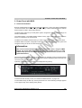
2.2.1 BIOS Setup Main Menu ........................................................................................
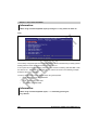
2.2.2 Motherboard Device Configuration .......................................................................
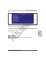
2.2.3 Drive Configuration ...............................................................................................
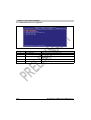
2.2.4 Memory Optimization ............................................................................................
2.2.5 Advanced BIOS Features .....................................................................................
2.2.6 Special OEM Features ..........................................................................................
2.2.7 Restore CMOS Values ..........................................................................................
2.2.8 Load Optimized Defaults .......................................................................................
2.2.9 Load Previous Values ...........................................................................................
2.2.10 Save Values without Exit ....................................................................................
2.2.11 Exit without Save ................................................................................................
2.2.12 Save Values and Exit ..........................................................................................
2.3 BIOS Update ...............................................................................................................
2.4 CMOS Backup .............................................................................................................
2.5 REMHOST ..................................................................................................................
2.5.1 General Information ..............................................................................................
2.5.2 Requirements ........................................................................................................
2.5.3 Important Notes ....................................................................................................
2.5.4 Configuration of REMHOST ..................................................................................
2.5.5 Program Start ........................................................................................................
10
125
125
125
126
126
127
127
129
129
132
133
137
139
141
145
146
147
147
148
148
149
150
151
151
152
152
152
153
Power Panel 100/200 User's Manual V 1.5
Table of Contents
154
154
154
154
155
155
157
158
158
158
158
159
159
PR
EL
IMI
NA
R
Y
2.5.6 Program End .........................................................................................................
2.5.7 Assignment for the Connection Cable ..................................................................
2.6 Distribution of Resources ............................................................................................
2.6.1 RAM Address Assignment ....................................................................................
2.6.2 Assignment of DMA channels ...............................................................................
2.6.3 I/O Address Assignment .......................................................................................
2.6.4 Interrupt Assignments ...........................................................................................
3. Windows CE .....................................................................................................................
3.1 General Information .....................................................................................................
3.2 What is Required? .......................................................................................................
3.3 Installation Procedures ................................................................................................
4. Windows XP Embedded ...................................................................................................
4.1 General Information .....................................................................................................
Chapter 5: Standards and Certifications .................................... 161
1. Valid European Guidelines ...............................................................................................
2. Valid Standards ................................................................................................................
3. Environmental Limits ........................................................................................................
4. Requirements for Immunity to Disturbances (EMC) .........................................................
5. Requirements for Emissions (EMC) .................................................................................
6. International Certifications ................................................................................................
161
161
161
161
161
161
Chapter 6: Accessories ................................................................ 163
1. Overview ...........................................................................................................................
2. Lithium Battery 0AC201.9 .................................................................................................
2.1 General Information .....................................................................................................
2.2 Order Data ...................................................................................................................
2.3 Technical Data ............................................................................................................
3. TB103 3-pin Supply Voltage Connector ...........................................................................
3.1 General Information .....................................................................................................
3.2 Order Data ...................................................................................................................
3.3 Technical Data ............................................................................................................
4. TB704 4-pin terminal blocks .............................................................................................
4.1 General Information .....................................................................................................
4.2 Order Data ...................................................................................................................
4.3 Technical Data ............................................................................................................
5. IF772 .................................................................................................................................
5.1 General Information .....................................................................................................
5.2 Order Data ...................................................................................................................
5.3 Technical Data ............................................................................................................
5.4 Operational and Connection Elements ........................................................................
5.5 CAN Node Number Switch ..........................................................................................
5.6 RS232 Interface (IF1) ..................................................................................................
5.7 Interfaces CAN 1 and CAN 2 (IF2 and IF3) .................................................................
6. IF786 .................................................................................................................................
6.1 General Information .....................................................................................................
Power Panel 100/200 User's Manual V 1.5
163
164
164
164
164
165
165
165
166
166
166
166
167
168
168
168
168
170
170
171
171
172
172
11
Table of Contents
172
173
174
174
174
175
177
178
179
179
179
179
180
180
180
181
182
182
182
183
185
186
187
187
188
188
188
189
189
189
190
191
191
191
192
194
195
195
196
196
196
197
197
197
197
PR
EL
IMI
NA
R
Y
6.2 Order Data ...................................................................................................................
6.3 Technical Data ............................................................................................................
6.4 Operational and Connection Elements ........................................................................
6.5 Status Display .............................................................................................................
6.5.1 RS232 Interface ....................................................................................................
6.5.2 ETHERNET Powerlink Interface ...........................................................................
6.6 ETHERNET Powerlink Station Number ....................................................................
6.7 ETHERNET Powerlink Interface (IF2) ......................................................................
6.8 RS232 Interface (IF1) ..................................................................................................
6.9 Firmware Update .........................................................................................................
6.9.1 SG3 .......................................................................................................................
6.9.2 SG4 .......................................................................................................................
7. IF787 .................................................................................................................................
7.1 General Information .....................................................................................................
7.2 Order Data ...................................................................................................................
7.3 Technical Data ............................................................................................................
7.4 Operational and Connection Elements ........................................................................
7.5 Status Display .............................................................................................................
7.5.1 CAN Interface .......................................................................................................
7.5.2 ETHERNET Powerlink Interface ...........................................................................
7.6 ETHERNET Powerlink Station Number ....................................................................
7.7 ETHERNET Powerlink Interface (IF2) ......................................................................
7.8 CAN Node Number .....................................................................................................
7.9 CAN Interface (IF1) .....................................................................................................
7.10 Firmware Update .......................................................................................................
7.10.1 SG3 .....................................................................................................................
7.10.2 SG4 .....................................................................................................................
8. IF789 .................................................................................................................................
8.1 General Information .....................................................................................................
8.2 Order Data ...................................................................................................................
8.3 Technical Data ............................................................................................................
8.4 Operational and Connection Elements ........................................................................
8.5 Status Display .............................................................................................................
8.5.1 X2X Link Interface .................................................................................................
8.5.2 ETHERNET Powerlink Interface ...........................................................................
8.6 ETHERNET Powerlink Station Number ....................................................................
8.7 ETHERNET Powerlink Interface (IF2) ......................................................................
8.8 X2X Link Interface (IF1) ..............................................................................................
8.9 Firmware Update .........................................................................................................
8.9.1 SG3 .......................................................................................................................
8.9.2 SG4 .......................................................................................................................
9. Compact Flash cards 5CFCRD.0xxx-01 ...........................................................................
9.1 General Information .....................................................................................................
9.2 Order Data ...................................................................................................................
9.3 Technical Data ............................................................................................................
12
Power Panel 100/200 User's Manual V 1.5
Table of Contents
Chapter 7: Maintenance and Service .......................................... 199
199
199
199
200
200
PR
EL
IMI
NA
R
Y
1. Operating Guidelines for the Touch Screen .....................................................................
2. Cleaning the Touch Screen ..............................................................................................
2.1 Cleaning Agent ............................................................................................................
3. Changing the Battery ........................................................................................................
3.1 Procedure for Changing the Battery ............................................................................
Power Panel 100/200 User's Manual V 1.5
13
PR
EL
IMI
NA
R
Y
Table of Contents
14
Power Panel 100/200 User's Manual V 1.5
Chapter 1
General Information
General Information • Manual History
Chapter 1 • General Information
Date
Comments
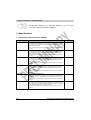
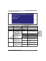
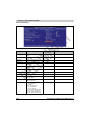
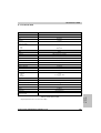
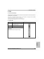
1.0
02.05.2002
Changes / New Features
- First version
PR
EL
IMI
NA
R
Version
Y
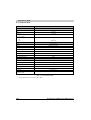
1. Manual History
1.1
20.08.2002
Changes / New Features
- Model numbers added for 24 VDC supply voltage plug
- Metal housing for PP120 versions 4PP120.0571-01 and 4PP120.0571-21 added
- Compact Flash cards (5CFCRD.0xxx-00) added
1.2
30.10.2002
Changes / New Features
- Layout - changes
1.3
06.12.2002
Changes / New Features
- Layout - changes
- Restructuring of the manual
- The following model numbers have either been updated or added: 4PP120.0571-01,
4PP120.0571-21, 4PP120.1043-31, 4PP120.1505-31, 4PP220.0571-45, 4PP220.0571-65,
4PP220.0571-85, 4PP220.0571-A5, 4PP220.1043-75, 4PP220.1043-B5, 4PP220.1505-75,
4PP220.1505-B5, 5PP120.0571-27, 5PP120.1043-37, 5PP120.1505-37, 0AC201.9, 0TB103.9
0TB103.91, 0TB704.9, 0TB704.91, 3IF772.9, 3IF786.9, 3IF787.9, 3IF789.9, 9A0013.01,
9S0001.13-010, 9S0001.13-02
New Chapter 3, 4, 5, 6, 7 added
1.4
27.03.2003
Changes / New Features
- Description of BIOS revised (table formatting, content)
1.5
28.04.2003
Changes / New Features
- Technical data for the 3-pin supply plug updated
- Mounting instructions (distance) and mounting position updated
- Following Power Panel devices added: 4PP210.0000-95, 4PP251.0571-65, 4PP251.0571-A5
- Battery change, battery buffer time updated
- Power conspumption and operating temperatures added
- BIOS update description added
- REMHOST description added
- CMOS backup description added
- Windows CE section updated
- Distribution of resources by BIOS added
- Delivery scope for each Power Panel device added
Table 1: Manual history
Power Panel 100/200 User's Manual V 1.5
15
General Information • Safety Guidelines
2. Safety Guidelines
2.1 Introduction
PR
EL
IMI
NA
R
Y
Programmable logic controllers (e.g. PLCs, etc.), operating and monitoring devices (e.g.
industrial PCs, Power Panels, mobile panels, etc.) as well as the B&R uninterruptible power
supplies have been designed, developed or manufactured for conventional use in industry. They
were not designed, developed and manufactured for any use involving serious risks or hazards
that without the implementation of exceptionally stringent safety precautions could lead to death,
injury, serious physical damage or loss of any other kind. Such risks and hazards include in
particular the use of these devices to monitor nuclear reactions in nuclear power plants, as well
as flight control systems, flight safety, the control of mass transportation systems, medical life
support systems, and the control of weapons systems.
Both when using programmable logic controllers and when using operating and monitoring
devices (such as control systems) together with a Soft PLC (e.g. B&R Automation Runtime or
comparable products) or a Slot PLC (e.g. B&R LS251 or comparable products), the safety
precautions applying to industrial control systems (e.g. the provision of safety devices such as
emergency stop circuits, etc.) must be observed in accordance with applicable national and
international regulations. The same applies for all other devices connected to the system, such
as drives.
All tasks such as installation, commissioning and service may only be carried out by qualified
personnel. Qualified personnel are persons who are familiar with the transport, mounting,
installation, commissioning and operation of the product and have the appropriate qualifications
(e.g. IEC 60364). National accident prevention guidelines must be followed.
The safety guidelines, connection descriptions (rating plate and documentation) and limit values
listed in the technical data must be read carefully before installation and commissioning and
must be observed.
2.2 Intended Use
Electronic devices are generally not fail-safe. In the event of a failure on the programmable
control system, operating or monitoring device or uninterruptible power supply, the user is
responsible for ensuring that other devices that may be connected, such as motors, are made
safe.
2.3 Transport and Storage
During transport and storage, devices must be protected from excessive stress (mechanical
load, temperature, humidity, aggressive atmosphere).
16
Power Panel 100/200 User's Manual V 1.5
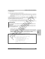
2.4 Installation
The installation must take place according to the documentation using suitable
equipment and tools.
•
The devices are only allowed to be installed without voltage applied and by qualified
personnel.
•
General safety regulations and nationally applicable accident prevention guidelines must
be observed.
•
Electrical installation must be carried out according to the relevant guidelines (e.g. line
cross section, fuse, protective ground connection).
Y
•
PR
EL
IMI
NA
R
2.5 Operation
2.5.1 Protection Against Touching Electrical Parts
To operate programmable logic controllers, operating and monitoring devices and uninterruptible
power supplies, certain components must carry dangerous voltage levels of over 42 VDC. A lifethreatening electrical shock could occur if you touch these parts. This could result in death,
severe injury or material damage.
Before turning on the programmable logic controller, the operational and monitoring devices and
the uninterruptible power supply, ensure that the housing is properly connected to protective
ground (PE rail). The ground connection must be established even when testing the operating
and monitoring devices or the uninterruptible power supply as well as when operating them for
only a short time.
Before switching on the device, make sure that all voltage carrying parts are securely covered.
During operation, all covers must remain closed.
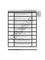
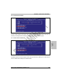
2.6 Safety Notices
Safety notices are organized as follows:
Safety Guidelines
Description
Danger!
Disregarding the safety regulations and guidelines can be life-threatening.
Caution!
Disregarding the safety regulations and guidelines can result in severe injury or major damage to material.
Warning!
Disregarding the safety regulations and guidelines can result in injury or damage to material.
Information
Important information for preventing errors
Table 2: Safety guidelines
Power Panel 100/200 User's Manual V 1.5
17
Chapter 1
General Information
General Information • Safety Guidelines
General Information • Model Numbers
All dimension diagrams (e.g. dimension diagrams, etc.) are drawn
according to European dimension standards.
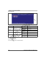
3. Model Numbers
Y
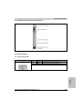
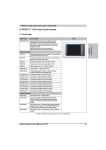
3.1 Power Panel with Automation Runtime
Description
Power Panel 120 LCD B/W QVGA 5.7in T MH
Power Panel PP120; 5.7in QVGA b/w LC display with touch screen (resistive), Compact
Flash slot (type I), ETH 10/100, RS 232, 2xUSB; 16 MB SDRAM; metal housing, IP 65
protection (from front); 24 VDC.
Plug for power supply must be ordered separately (screw clamp: 0TB103.9, cage clamp:
0TB103.91).
Note
4PP120.0571-21
Power Panel 120 LCD C QVGA 5.7in T MH
Power Panel PP120; 5.7in QVGA color LC display with touch screen (resistive), Compact
Flash slot (type I), ETH 10/100, RS 232, 2xUSB; 16 MB SDRAM; metal housing, IP 65
protection (from front); 24 VDC.
Plug for power supply must be ordered separately (screw clamp: 0TB103.9, cage clamp:
0TB103.91).
4PP120.1043-31
Power Panel 120 TFT C VGA 10.4in T MH
Power Panel PP120; 10.4in VGA TFT color display with touch screen (resistive), Compact
Flash slot (type I), ETH 10/100, RS 232, 2xUSB; 16 MB SDRAM; metal housing, IP 65
protection (from front); 24 VDC.
Plug for power supply must be ordered separately (screw clamp: 0TB103.9, cage clamp:
0TB103.91).
4PP120.1505-31
Power Panel 120 TFT C XGA 15in T MH
Power Panel PP120; 15in XGA TFT color display with touch screen (resistive), Compact
Flash slot (type I), ETH 10/100, RS 232, 2xUSB; 16 MB SDRAM; metal housing, IP 65
protection
(from front); 24 VDC.
Plug for power supply must be ordered separately (screw clamp: 0TB103.9, cage clamp:
0TB103.91).
4PP210.0000-95
Power Panel 210 Controller MH 2aPCI
Power Panel PP210 controller, Compact Flash slot (type I), ETH 10/100, RS 232, 2xUSB;
64 MB SDRAM; 2 aPCI slots; 256 kB SRAM; battery; metal housing, IP 65 protection (from
front); 24 VDC.
Plug for power supply must be ordered separately (screw clamp: 0TB103.9, cage clamp:
0TB103.91)
4PP220.0571-45
Power Panel 220 LCD B/W QVGA 5.7in T MH 1aPCI
Power Panel PP220; 5.7in QVGA b/w LC display with touch screen (resistive), Compact
Flash slot (type I), ETH 10/100, RS 232, 2xUSB; 64 MB SDRAM; 1 aPCI Slot; 256 kB SRAM;
battery; metal housing, IP 65 protection (from front); 24 VDC.
Plug for power supply must be ordered separately (screw clamp: 0TB103.9, cage clamp:
0TB103.91).
PR
EL
IMI
NA
R
Model Number
4PP120.0571-01
Table 3: Model numbers for Power Panel with Automation Runtime
18
Power Panel 100/200 User's Manual V 1.5
General Information • Model Numbers
Power Panel 220 LCD C QVGA 5.7in T MH 1aPCI
Power Panel PP220; 5.7in QVGA color LC display with touch screen (resistive), Compact
Flash slot (type I), ETH 10/100, RS 232, 2xUSB; 64 MB SDRAM; 1 aPCI slot; 256 kB SRAM;
battery; metal housing, IP 65 protection (from front); 24 VDC.
Plug for power supply must be ordered separately (screw clamp: 0TB103.9, cage clamp:
0TB103.91).
Note
4PP220.0571-85
Power Panel 220 LCD B/W QVGA 5.7in T MH 2aPCI
Power Panel PP220; 5.7in QVGA b/w LC display with touch screen (resistive), Compact
Flash slot (type I), ETH 10/100, RS 232, 2xUSB; 64 MB SDRAM; 2 aPCI slots; 256 kB SRAM;
battery; metal housing, IP 65 protection (from front); 24 VDC.
Plug for power supply must be ordered separately (screw clamp: 0TB103.9, cage clamp:
0TB103.91).
4PP220.0571-A5
Power Panel 220 LCD C QVGA 5.7in T MH 2aPCI
Power Panel PP220; 5.7in QVGA color LC display with touch screen (resistive), Compact
Flash slot (type I), ETH 10/100, RS 232, 2xUSB; 64 MB SDRAM; 2 aPCI slots; 256 kB SRAM;
battery; metal housing, IP 65 protection (from front); 24 VDC.
Plug for power supply must be ordered separately (screw clamp: 0TB103.9, cage clamp:
0TB103.91).
Chapter 1
General Information
Description
4PP220.0571-65
PR
EL
IMI
NA
R
Y
Model Number
4PP220.1043-75
Power Panel 220 TFT C VGA 10.4in T MH 1aPCI
Power Panel PP220; 10.4in VGA color TFT display with touch screen (resistive), Compact
Flash slot (type I), ETH 10/100, RS 232, 2xUSB; 64 MB SDRAM; 1 aPCI slot; 256 kB SRAM;
battery; metal housing, IP 65 protection (from front); 24 VDC.
Plug for power supply must be ordered separately (screw clamp: 0TB103.9, cage clamp:
0TB103.91).
4PP220.1043-B5
Power Panel 220 TFT C VGA 10.4in T MH 2aPCI
Power Panel PP220; 10.4in VGA color TFT display with touch screen (resistive), Compact
Flash slot (type I), ETH 10/100, RS 232, 2xUSB; 64 MB SDRAM; 2 aPCI slots; 256 kB SRAM;
battery; metal housing, IP 65 protection (from front); 24 VDC.
Plug for power supply must be ordered separately (screw clamp: 0TB103.9, cage clamp:
0TB103.91).
4PP220.1505-75
Power Panel 220 TFT C XGA 15in T MH 1aPCI
Power Panel PP220; 15in XGA color TFT Display with touch screen (resistive), Compact
Flash slot (type I), ETH 10/100, RS 232, 2xUSB; 64 MB SDRAM; 1 aPCI slot; 256 kB SRAM;
battery; metal housing, IP 65 protection (from front); 24 VDC.
Plug for power supply must be ordered separately (screw clamp: 0TB103.9, cage clamp:
0TB103.91).
In preparation
4PP220.1505-B5
Power Panel 220 TFT C XGA 15in T MH 2aPCI
Power Panel PP220; 15in XGA color TFT display with touch screen (resistive), Compact
Flash slot (type I), ETH 10/100, RS 232, 2xUSB; 64 MB SDRAM; 2 aPCI slots; 256 kB SRAM;
battery; metal housing, IP 65 protection (from front); 24 VDC.
Plug for power supply must be ordered separately (screw clamp: 0TB103.9, cage clamp:
0TB103.91).
In preparation
4PP251.0571-65
Power Panel 251 LCD C QVGA 5.7in F MH 1aPCI
Power Panel PP251; 5.7in QVGA color LC display; 6 softkeys; 16 function keys and 20
system keys; 1 aPCI slot; 64 MB SDRAM; 256 kB SRAM Compact Flash slot (type I); ETH
10/100; RS 232; 2xUSB; battery; metal housing, IP 65 protection (from front); 24 VDC.
Plug for power supply must be ordered separately (screw clamp: 0TB103.9; cage clamps:
0TB103.91).
In preparation
4PP251.0571-A5
Power Panel 251 LCD C QVGA 5.7in F MH 2aPCI
Power Panel PP251 5.7in QVGA color LC display; 6 softkeys; 16 function keys and 20 system
keys; 2 aPCI slots; 64 MB SDRAM; 256 kB SRAM Compact Flash slot (type I); ETH 10/100;
RS 232; 2xUSB; battery; metal housing, IP 65 protection (from front); 24 VDC.
Plug for power supply must be ordered separately (screw clamp: 0TB103.9; cage clamps:
0TB103.91).
In preparation
Table 3: Model numbers for Power Panel with Automation Runtime (cont.)
Power Panel 100/200 User's Manual V 1.5
19
General Information • Model Numbers
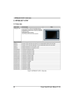
3.2 Power Panel with BIOS
Description
Power Panel 120 LCD C QVGA 5.7in T MH
Power Panel PP120 BIOS; 5.7in QVGA color LC display with touch screen (resistive),
Compact Flash slot (type I), ETH 10/100, RS 232, 2xUSB; 128 MB SDRAM; battery; metal
housing, IP 65 protection (from front); 24 VDC.
Plug for power supply must be ordered separately (screw clamp: 0TB103.9, cage clamp:
0TB103.91).
Note
5PP120.1043-37
Power Panel 120 TFT C VGA 10.4in T MH
Power Panel PP120 BIOS; 10.4in VGA TFT color display with touch screen (resistive),
Compact Flash slot (type I), ETH 10/100, RS 232, 2xUSB; 128 MB SDRAM; battery; metal
housing, IP 65 protection (from front); 24 VDC.
Plug for power supply must be ordered separately (screw clamp: 0TB103.9, cage clamp:
0TB103.91).
PR
EL
IMI
NA
R
Y
Model Number
5PP120.0571-27
5PP120.1505-37
Power Panel 120 TFT C XGA 15in T MH
Power Panel PP120 BIOS; 15in XGA TFT color display with touch screen (resistive),
Compact Flash slot (type I), ETH 10/100, RS 232, 2xUSB; 128 MB SDRAM; battery; metal
housing, IP 65 protection (from front); 24 VDC.
Plug for power supply must be ordered separately (screw clamp: 0TB103.9, cage clamp:
0TB103.91).
Table 4: Model numbers for Power Panel with BIOS
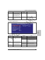
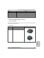
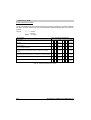
3.3 Accessories
Model Number
Description
0AC201.9
Lithium Batteries (5 pcs.)
Lithium batteries, 5 pcs., 3 V / 950 mAh
0TB103.9
Plug for the 24 V Supply Voltage (screw clamps)
Plug 24 V 5.08 3-pin Screw clamps
0TB103.91
Plug for the 24 V Supply Voltage (cage clamps)
Plug 24 V 5.08 3-pin Cage clamps
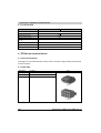
0TB704.9
Accessory 4-pin Screw Clamp , 5.08
Accessory, terminal block, 4-pin, screw clamps, 1.5 mm2
0TB704.91
Accessory 4-pin Cage Clamp , 5.08
Accessory, terminal block, 4-pin, cage clamps, 2.5 mm2
3IF772.9
aPCI Interface 2x CAN, 1x RS232
aPCI interface module, 1 RS232 interface, 2 CAN interfaces, max. 500 kbps,
CAN: electrically isolated, network capable, object buffer in send and receive directions
Order 2 x TB704 terminal blocks separately.
3IF786.9
aPCI interface 1x POWERLINK, 1x RS232
aPCI interface modules, 1 ETHERNET Powerlink interface, manager or controller function, 1
RS232 interface
3IF787.9
aPCI Interface 1x POWERLINK, 1x CAN
aPCI interface module, 1 ETHERNET Powerlink interface, manager or controller function, 1
CAN interface, max. 500 kbps, object buffer in send and receive direction, network capable,
electrically isolated. Order 1 x TB704 terminal block separately.
3IF789.9
aPCI interface 1x POWERLINK, 1x X2X-LINK
aPCI interface interface module, 1ETHERNET Powerlink interface, manager or controller
function, 1X2X Link Master interface, electrically isolated. Order TB704 terminal block
separately.
Note
Table 5: Model numbers for accessories
20
Power Panel 100/200 User's Manual V 1.5
General Information • Model Numbers
Note
5CFCRD.0064-01
Compact Flash 64 MB ATA/True IDE
Compact Flash card with 64 MB FPROM, and true IDE/ATA interface.
5CFCRD.0128-01
Compact Flash 128 MB ATA/True IDE
Compact Flash card with 128 MB FPROM, and true IDE/ATA interface.
5CFCRD.0128-01
Compact Flash 196 MB ATA/True IDE
Compact Flash card with 196 MB FPROM, and true IDE/ATA interface.
5CFCRD.0256-01
Compact Flash 256 MB ATA/True IDE
Compact Flash card with 256 MB FPROM, and true IDE/ATA interface.
5CFCRD.0384-01
Compact Flash 384 MB ATA/True IDE
Compact Flash card with 384 MB FPROM, and true IDE/ATA interface.
Chapter 1
General Information
Compact Flash 32 MB ATA/True IDE
Compact Flash card with 32 MB FPROM, and true IDE/ATA interface.
Y
Description
5CFCRD.0032-01
PR
EL
IMI
NA
R
Model Number
5CFCRD.0512-01
Compact Flash 512 MB ATA/True IDE
Compact Flash card with 512 MB FPROM, and true IDE/ATA interface.
9A0013.01
Pen for Resistive Touch Screen
9A0017.01
RS232 Null Modem Cable 0.6 m
To connect the Power Panel to the remote PC (9-pin DSUB socket - 9-pin DSUB socket)
9A0017.02
RS232 Null Modem Cable 1.8 m
To connect the Power Panel to the remote PC (9-pin DSUB socket - 9-pin DSUB socket)
Table 5: Model numbers for accessories (cont.)
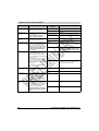
3.4 Software
Model Number
Description
5S0000.01-090
HMI Drivers & Utilities CD
9S0001.13-010
OEM MS-Win CE4.1 German
Only delivered with a Power Panel BIOS device
9S0001.13-020
OEM MS-Win CE4.1 English
Only delivered with a Power Panel BIOS device
Table 6: Software model numbers
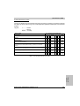
3.5 Documentation
Model Number
Description
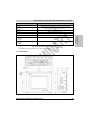
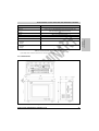
MAPP02-0
Power Panel 100 / 200 User's Manual, English
In preparation
MAPP02-E
Power Panel 100/200 User's Manual, English
In preparation
Table 7: Model numbers for documentation
Power Panel 100/200 User's Manual V 1.5
21
PR
EL
IMI
NA
R
Y
General Information • Model Numbers
22
Power Panel 100/200 User's Manual V 1.5
Technical Data • General Information
Chapter 2 • Technical Data
PR
EL
IMI
NA
R
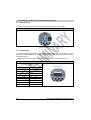
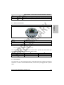
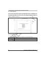
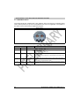
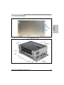
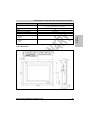
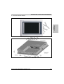
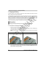
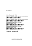
B&R offers the B&R Power Panel 100 and Power Panel 200 product range for automation of
small to midsize machines and systems.
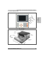
The Power Panel 100 and Power Panel 200 product range encompasses a line of devices from
operating units with QVGA, VGA or XGA display to visualization devices and machines
controllers. Programmable with Automation Studio (Visual Components), these devices close
the gap between Panelware and IPC based systems. Depending on the design, the devices
contain the embedded operating system Automation Runtime or a BIOS based operating system
such as Windows CE or Windows XP embedded. The number of onboard interfaces is reduced
to a minimum and size is optimized to the smallest dimensions.
Depending on the model, the devices have a 5.7 inch QVGA touch screen available in either
color or black/white, as well as a 10.4 inch VGA or a 15 inch XGA touch screen in color.
Additionally, there are horizontally or vertically formatted devices available (numeric and
alphanumeric keys, with or without insert strips) for all display sizes.
Figure 1: Power Panel
Power Panel 100/200 User's Manual V 1.5
23
Chapter 2
Technical Data
Y
1. General Information
Technical Data • General Information
1.1 Features
•
24 VDC supply voltage
•
2 USB connections
•
Ethernet 10/100 MBit interface
Compact Flash slot
•
RS232 interface, modem capable, not electrically isolated
•
2 operating mode switches (2 x 16 digit)
•
Touch screen (analog resistive), function keys or both
•
Horizontal and vertical mounting placements, numeric and alphanumeric keys
PR
EL
IMI
NA
R
Y
•
24
•
2 status LEDs (User and Compact Flash)
•
Software compatible with B&R 2000 PLC family
•
aPCI Slots
•
Fan free operation
•
BIOS or Automation Runtime
•
Real-time clock (battery-buffered)
•
Up to 128 MB main memory
Power Panel 100/200 User's Manual V 1.5
Technical Data • Power Panel 100 with Automation Runtime
2. Power Panel 100 with Automation Runtime
2.1 Device Interfaces
In the following section, a description is given for all interfaces and plugs available to the
Power Panel.
PR
EL
IMI
NA
R
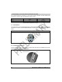
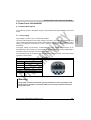
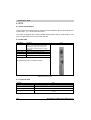
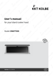
The 3-pin socket required for the supply voltage connection is not included in the delivery. This
can be ordered from B&R using the model number 0TB103.9 (screw clamp) or 0TB103.91 (cage
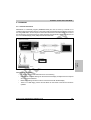
clamp). The cable required for the connection must be supplied by the customer (see also
section "Windows XP Embedded", on page 159).
The supply voltage is protected by a self-healing fuse which means that the device is not
damaged if there is an overload, or if the supply voltage is incorrectly connected. Additionally, it
also means that the fuse does not need to be changed.
The pin assignments can be found in the table below and are also printed on the Power Panel
type plate or device label.
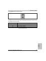
Supply Voltage
Pin
Assignment
1
+
2
Ground
3
-
Accessories
0TB103.9
Plug 24 V 5.08 3p screw clamps
0TB103.91
Plug 24 V 5.08 3p cage clamps
Figure 2: Supply voltage connection
Warning!
The ground connection (functional ground) should be as short as possible. If the
Power Panel is installed in a switching cabinet, the connection cable should not be
longer than 15 cm.
Power Panel 100/200 User's Manual V 1.5
25
Chapter 2
Technical Data
Input Voltage: 24 VDC ± 25%, not electrically isolated
Y
2.1.1 Power Supply
Technical Data • Power Panel 100 with Automation Runtime
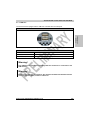
2.1.2 Grounding Clip
The ground clip should be connected to ground using the shortest route possible.
PR
EL
IMI
NA
R
Y
Grounding Clip
Figure 3: Grounding clip
2.1.3 COM Interface
The Power Panel is equipped with a PC compatible serial interface with 16 bytes FIFO. This nonelectrically isolated interface is primarily intended for programming the Power Panel using
Automation Studio.
The RS232 can also be used as a general interface (e.g. printer, bar code reader, etc.).
Serial Interface
RS232 Interface
modem capable, not electrically isolated
Up to 115 kBaud
Pin
RS232
1
DCD
2
RXD
3
TxD
4
DTR
5
GND
6
DSR
7
RTS
8
CTS
9
RI
9-pin DSUB connector
Table 8: COM pin assignment
26
Power Panel 100/200 User's Manual V 1.5
Technical Data • Power Panel 100 with Automation Runtime
2.1.4 USB Port
The Power Panel is equipped with a USB host controller with two USB ports.
PR
EL
IMI
NA
R
Y
Chapter 2
Technical Data
Universal Serial Bus
Figure 4: USB port
Technical Data for USB Port
Transfer Rate
1.5 MBit/s and 12 MBit/s
Power Supply
500 mA per port
Maximum Cable Length
5 m (can possibly be extended using a USB hub)
Table 9: Technical data for USB connection
Warning!
Only USB devices tested and verified by B&R are allowed to be connected to the
USB interface.
Caution!
Because of general PC specifications, this interface should be handled with extreme
care with regard to EMC, location of cables etc.
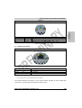
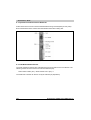
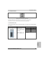
2.1.5 Mode/Node Switch
The Power Panels are equipped with 2 hex switches, which are used as an operating mode
switch. Switch positions 01 up to FD are available to the user in an application. The position of
the switch can be evaluated by an application program.
Power Panel 100/200 User's Manual V 1.5
27
Technical Data • Power Panel 100 with Automation Runtime
PR
EL
IMI
NA
R
Figure 5: Mode/node switch
Y
Mode/Node Switch
Switch Position
Function
Description
SW1 (x16)
SW2 (x1)
Operating Mode Switch
0
0
Boot
Automation Runtime boot mode for operating system (firmware) upgrade (default
Automation Runtime)
A new operating system is downloaded.
0 to F
1 to D
Node
Automation Runtime run mode with node 01-FD (Compact Flash Automation Runtime
or terminal operation)
Freely available for use in an application e.g. setting the INA2000 station number for the
Ethernet interface
F
E
Dyn. Mode
Automation Runtime run mode with node 01-FD (Compact Flash Automation Runtime
or terminal operation)
Device addresses can be defined by the software
F
F
Diagnosis
Automation Runtime diagnose mode (Compact Flash Automation Runtime or Terminal
Operation)
Table 10: Switch settings for the mode/node switch
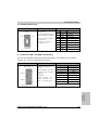
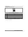
2.1.6 Status LEDs
Power Panels are equipped with two status LEDs which are visible on the outside.
Status LEDs
Figure 6: Status LEDs
28
Power Panel 100/200 User's Manual V 1.5
Technical Data • Power Panel 100 with Automation Runtime
LED
Color
Function
User
Green
Freely available for use in an application (corresponding libraries for Automation Studio in preparation)
CF
Yellow
Indicates the access to a Compact Flash card present
Table 11: Status LEDs
2.1.7 Ethernet Connection
PR
EL
IMI
NA
R
Y
Chapter 2
Technical Data
Ethernet Connection
Figure 7: Ethernet connection
Ethernet
10/100 MBit/s 1)
Connection
RJ45 twisted pair (10BaseT/100BaseT)
Controller
MacPhyter DP83815
Cabling
S/STP (category 5)
Table 12: Ethernet controller
1) Both operating modes are possible. Switching takes place automatically
The onboard Ethernet controller for Power Panel devices provides an RJ45 twisted pair
connection, to which 2 LEDs are attached for status control:
LED
On
Off
Green
100 MBit/s
10 MBit/s
Yellow
Link
Activity (blinking)
Table 13: Status LEDs Ethernet controller
2.1.8 Reset Button
The reset button can be accessed through a small hole between the USB and the Ethernet
connection. In order to avoid accidental activation, a reset can only be triggered with a pointed
object.
Power Panel 100/200 User's Manual V 1.5
29
Technical Data • Power Panel 100 with Automation Runtime
PR
EL
IMI
NA
R
Figure 8: Reset button
Y
Reset Button
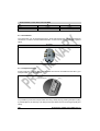
2.1.9 Compact Flash Slot
Power Panels are equipped with a Compact Flash slot which is accessible from the side. Type I
Compact Flash cards are supported.
Figure 9: Compact Flash slot
It is possible to protect the Compact Flash slot using a safety clip. By pressing the ejector (using
a pointed object is the best way to do this) the Compact Flash card can be changed quickly and
safely.
Caution!
Changing the Compact Flash card can only take place without power applied!
30
Power Panel 100/200 User's Manual V 1.5
Technical Data • Power Panel 100 with Automation Runtime
2.2 Label
2.2.1 Device Label
PR
EL
IMI
NA
R
Y
Chapter 2
Technical Data
The following label attached in a suitable location on the Power Panel, contains short definitions
for all of the interfaces:
Figure 10: Device label
2.2.2 Serial Number Label
General Information
Each B&R device is assigned a unique serial number label with a bar code, allowing the device
to be clearly identified.
Design and Dimensions
Figure 11: Design and dimensions of serial number label
Power Panel 100/200 User's Manual V 1.5
31
Technical Data • Power Panel 100 with Automation Runtime
PR
EL
IMI
NA
R
Y
This page is only used as a place holder.
32
Power Panel 100/200 User's Manual V 1.5
Technical Data • Power Panel 100 with Automation Runtime
PR
EL
IMI
NA
R
Y
Chapter 2
Technical Data
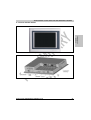
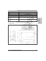
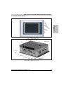
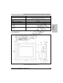
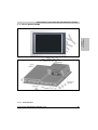
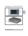
2.3 Device 4PP120.0571-01
Figure 12: Front view 4PP120.0571-01
Figure 13: Rear view 4PP120.0571-01
Power Panel 100/200 User's Manual V 1.5
33
Technical Data • Power Panel 100 with Automation Runtime
2.3.1 Technical Data
Features
4PP120.0571-01
Bootloader
Automation Runtime
Processor
Geode SC2200 266 MHz, MMX compatible
Flash
2 MB, onboard, for firmware
Main Memory
16 MB DRAM
4 MB shared memory (reserved by the main memory)
SRAM, 256 KB Onboard, Battery Backed
-
Watchdog, SMC Internal
-
Power Fail Logic, SMC 10 ms Buffer Time
-
Yes, not battery backed
PR
EL
IMI
NA
R
Real-time Clock
Y
Graphic Memory
Battery (Lithium, 950mAh, exchange from outside)
Ethernet
Controller (onboard)
Connection
Cabling
Compact Flash Slot
Serial Interface(COM)
-
MacPhyter DP83815 ; 10/100 Mbit/s
RJ 45 twisted pair (10 BaseT / 100 BaseT)
S/STP (category 5)
1 slot for type I Compact Flash cards
RS232; modem capable; not electrically isolated
USB
2x USB 1.1, connection type A
LEDs
1 LED user (green), 1 LED CF (yellow)
Mode/Node Switch
aPCI Slots
Display
Type
Diagonal
Colors
Resolution
Background Lighting
Brightness
Half Brightness Time
Touch Screen
Technology
Controller
Front
Frame
Mylar
Gasket
Keys
Function Keys
Function Keys with LEDs
Softkeys
Softkeys with LEDs
System Keys
System Keys with LEDs
Supply Voltage
2 pcs. each 16 digits
-
LCD
5.7 in
8 shades of gray
QVGA, 320 x 240 pixels
140 cd/m²
20,000 hours
Analog, resistive (Gunze)
Serial (Hampshire)
Aluminum anodized
Polyester, light gray
Flat gasket around display front
-
24 VDC ± 25%, not electrically isolated
Table 14: Technical data 4PP120.0571-01
34
Power Panel 100/200 User's Manual V 1.5
Technical Data • Power Panel 100 with Automation Runtime
Features
4PP120.0571-01
Power Consumption
Approx. 10 Watt1)
Protection
IP20 back side (only with installed Compact Flash card)
IP65, dust and sprayed water protection from front
Housing
Metal
Weight
Approx. 1.4 kg
Outer Dimensions in mm (WxHxD)
212 x 156 x 55.5
TBD
Environmental Temperature
Operation
Storage
Chapter 2
Technical Data
Altitude
Relative Humidity
Operation
Storage
PR
EL
IMI
NA
R
TBD
TBD
Y
0 - 50° C
TBD
Table 14: Technical data 4PP120.0571-01 (cont.)
1) The starting current can amount to around 20 A for a short period (approx.1 ms).
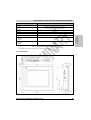
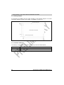
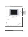
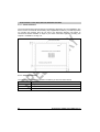
2.3.2 Dimensions
Figure 14: Dimensions 4PP120.0571-01
Power Panel 100/200 User's Manual V 1.5
35
Technical Data • Power Panel 100 with Automation Runtime
2.3.3 Cutout Installation
PR
EL
IMI
NA
R
Y
The cutout hole must be made according to the following dimensions for cutout installation. The
device must be mounted with the 4 retaining clips supplied with the delivery. The defined position
for mounting the retaining clips can be seen in the dimension diagram (see Figure 14
"Dimensions 4PP120.0571-01" on Page 35) For further information regarding mounting, see
Chapter 3 "Installation" on Page 121.
Figure 15: Cutout dimensions
2.3.4 Contents of Delivery
The following components are included in the delivery of the Power Panel device:
Amount
Component
1
Power Panel 120 LCD B/W QVGA 5.7in T MH
4
Retaining clips included
Table 15: Delivery 4PP120.0571-01
36
Power Panel 100/200 User's Manual V 1.5
Technical Data • Power Panel 100 with Automation Runtime
PR
EL
IMI
NA
R
Y
Chapter 2
Technical Data
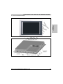
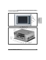
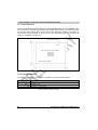
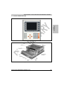
2.4 Device 4PP120.0571-21
Figure 16: Front view 4PP120.0571-21
Figure 17: Rear view 4PP120.0571-21
Power Panel 100/200 User's Manual V 1.5
37
Technical Data • Power Panel 100 with Automation Runtime
2.4.1 Technical Data
Features
4PP120.0571-21
Bootloader
Automation Runtime
Processor
Geode SC2200 266 MHz, MMX compatible
Flash
2 MB, onboard, for firmware
Main Memory
16 MB DRAM
4 MB shared memory (reserved by the main memory)
SRAM, 256 KB Onboard, Battery Backed
-
Watchdog, SMC Internal
-
Power Fail Logic, SMC 10 ms Buffer Time
-
Yes, not battery backed
PR
EL
IMI
NA
R
Real-time Clock
Y
Graphic Memory
Battery (Lithium, 950mAh, exchange from outside)
Ethernet
Controller (onboard)
Connection
Cabling
Compact Flash Slot
Serial Interface(COM)
-
MacPhyter DP83815 ; 10/100 Mbit/s
RJ 45 twisted pair (10 BaseT / 100 BaseT)
S/STP (category 5)
1 slot for type I Compact Flash cards
RS232; modem capable; not electrically isolated
USB
2x USB 1.1, connection type A
LEDs
1 LED user (green), 1 LED CF (yellow)
Mode/Node Switch
aPCI Slots
Display
Type
Diagonal
Colors
Resolution
Background Lighting
Brightness
Half Brightness Time
Touch Screen
Technology
Controller
Front
Frame
Mylar
Gasket
Keys
Function Keys
Function Keys with LEDs
Softkeys
Softkeys with LEDs
System Keys
System Keys with LEDs
Supply Voltage
2 pcs. each 16 digits
-
LCD
5,7 in
256 Colors
QVGA, 320 x 240 pixels
150 cd/m²
50,000 hours
Analog, resistive (Gunze)
Serial (Hampshire)
Aluminum anodized
Polyester, light gray
Flat gasket around display front
-
24 VDC ± 25%, not electrically isolated
Table 16: Technical data 4PP120.0571-21
38
Power Panel 100/200 User's Manual V 1.5
Technical Data • Power Panel 100 with Automation Runtime
Features
4PP120.0571-21
Power Consumption
Approx. 10 Watt1)
Protection
IP20 back side (only with installed Compact Flash card)
IP65, dust and sprayed water protection from front
Housing
Metal
Weight
Approx. 1.4 kg
Outer Dimensions in mm (WxHxD)
212 x 156 x 55.5
TBD
Environmental Temperature
Operation
Storage
Chapter 2
Technical Data
Altitude
Relative Humidity
Operation
Storage
PR
EL
IMI
NA
R
TBD
TBD
Y
0 - 50° C
TBD
Table 16: Technical data 4PP120.0571-21 (cont.)
1) The starting current can amount to around 20 A for a short period (approx.1 ms).
2.4.2 Dimensions
Figure 18: Dimensions 4PP120.0571-21
Power Panel 100/200 User's Manual V 1.5
39
Technical Data • Power Panel 100 with Automation Runtime
2.4.3 Cutout Installation
PR
EL
IMI
NA
R
Y
The cutout hole must be made according to the following dimensions for cutout installation. The
device must be mounted with the 4 retaining clips supplied with the delivery. The defined position
for mounting the retaining clips can be seen in the dimension diagram (see Figure 18
"Dimensions 4PP120.0571-21" on Page 39) For further information regarding mounting, see
Chapter 3 "Installation" on Page 121.
Figure 19: Cutout dimensions
2.4.4 Contents of Delivery
The following components are included in the delivery of the Power Panel device:
Amount
Component
1
Power Panel 120 LCD C QVGA 5.7in T MH
4
Retaining clips included
Table 17: Delivery 4PP120.0571-21
40
Power Panel 100/200 User's Manual V 1.5
Technical Data • Power Panel 100 with Automation Runtime
PR
EL
IMI
NA
R
Y
Chapter 2
Technical Data
2.5 Device 4PP120.1043-31
Figure 20: Front view 4PP120.1043-31
Figure 21: Rear view 4PP120.1043-31
Power Panel 100/200 User's Manual V 1.5
41
Technical Data • Power Panel 100 with Automation Runtime
2.5.1 Technical Data
Features
4PP120.1043-31
Bootloader
Automation Runtime
Processor
Geode SC2200 266 MHz, MMX compatible
Flash
2 MB, onboard, for firmware
Main Memory
16 MB DRAM
4 MB shared memory (reserved by the main memory)
SRAM, 256 KB Onboard, Battery Backed
-
Watchdog, SMC Internal
-
Power Fail Logic, SMC 10 ms Buffer Time
-
Yes, not battery backed
PR
EL
IMI
NA
R
Real-time Clock
Y
Graphic Memory
Battery (Lithium, 950mAh, exchange from outside)
Ethernet
Controller (onboard)
Connection
Cabling
Compact Flash Slot
Serial Interface(COM)
-
MacPhyter DP83815 ; 10/100 Mbit/s
RJ 45 twisted pair (10 BaseT / 100 BaseT)
S/STP (category 5)
1 slot for type I Compact Flash cards
RS232; modem capable; not electrically isolated
USB
2x USB 1.1, connection type A
LEDs
1 LED user (green), 1 LED CF (yellow)
Mode/Node Switch
aPCI Slots
Display
Type
Diagonal
Colors
Resolution
Background Lighting
Brightness
Half Brightness Time
Touch Screen
Technology
Controller
Front
Frame
Mylar
Gasket
Keys
Function Keys
Function Keys with LEDs
Softkeys
Softkeys with LEDs
System Keys
System Keys with LEDs
Supply Voltage
2 pcs. each 16 digits
-
TFT
10,4 in
256 Colors
VGA, 640 x 480 pixels
350 cd/m²
55,000 hours
Analog, resistive (3M)
Serial (Hampshire)
Aluminum anodized
Polyester, light gray
Flat gasket around display front
-
24 VDC ± 25%, not electrically isolated
Table 18: Technical data 4PP120.1043-31
42
Power Panel 100/200 User's Manual V 1.5
Technical Data • Power Panel 100 with Automation Runtime
Features
4PP120.1043-31
Power Consumption
Approx. 15 Watt1)
Protection
IP20 back side (only with installed Compact Flash card)
IP65, dust and sprayed water protection from front
Housing
Metal
Weight
Approx. 2 kg
Outer Dimensions in mm (WxHxD)
323 x 260 x 65.5
TBD
Environmental Temperature
Operation
Storage
Chapter 2
Technical Data
Altitude
Relative Humidity
Operation
Storage
PR
EL
IMI
NA
R
TBD
TBD
Y
0 - 50° C
TBD
Table 18: Technical data 4PP120.1043-31 (cont.)
1) The starting current can amount to around 20 A for a short period (approx.1 ms).
2.5.2 Dimensions
Figure 22: Dimensions 4PP120.1043-31
Power Panel 100/200 User's Manual V 1.5
43
Technical Data • Power Panel 100 with Automation Runtime
2.5.3 Cutout Installation
PR
EL
IMI
NA
R
Y
The cutout hole must be made according to the following dimensions for cutout installation. The
device must be mounted with the 6 retaining clips supplied with the delivery. The defined position
for mounting the retaining clips can be seen in the dimension diagram (see Figure 22
"Dimensions 4PP120.1043-31" on Page 43) For further information regarding mounting, see
Chapter 3 "Installation" on Page 121.
Figure 23: Cutout dimensions
2.5.4 Contents of Delivery
The following components are included in the delivery of the Power Panel device:
Amount
Component
1
Power Panel 120 TFT C VGA 10.4in T MH
6
Retaining clips included
Table 19: Delivery 4PP120.1043-31
44
Power Panel 100/200 User's Manual V 1.5
Technical Data • Power Panel 100 with Automation Runtime
PR
EL
IMI
NA
R
Y
Chapter 2
Technical Data
2.6 Device 4PP120.1505-31
Figure 24: Front view 4PP120.1505-31
Figure 25: Rear view 4PP120.1505-31
Power Panel 100/200 User's Manual V 1.5
45
Technical Data • Power Panel 100 with Automation Runtime
2.6.1 Technical Data
Features
4PP120.1505-31
Bootloader
Automation Runtime
Processor
Geode SC2200 266 MHz, MMX compatible
Flash
2 MB, onboard, for firmware
Main Memory
16 MB DRAM
4 MB shared memory (reserved by the main memory)
SRAM, 256 KB Onboard, Battery Backed
-
Watchdog, SMC Internal
-
Power Fail Logic, SMC 10 ms Buffer Time
-
Yes, not battery backed
PR
EL
IMI
NA
R
Real-time Clock
Y
Graphic Memory
Battery (Lithium, 950mAh, exchange from outside)
Ethernet
Controller (onboard)
Connection
Cabling
Compact Flash Slot
Serial Interface(COM)
-
MacPhyter DP83815 ; 10/100 Mbit/s
RJ 45 twisted pair (10 BaseT / 100 BaseT)
S/STP (category 5)
1 slot for type I Compact Flash cards
RS232; modem capable; not electrically isolated
USB
2x USB 1.1, connection type A
LEDs
1 LED user (green), 1 LED CF (yellow)
Mode/Node Switch
aPCI Slots
Display
Type
Diagonal
Colors
Resolution
Background Lighting
Brightness
Half Brightness Time
Touch Screen
Technology
Controller
Front
Frame
Mylar
Gasket
Keys
Function Keys
Function Keys with LEDs
Softkeys
Softkeys with LEDs
System Keys
System Keys with LEDs
Supply Voltage
Power Consumption
2 pcs. each 16 digits
-
TFT
15 in
256 Colors
XGA, 1024 x 768 pixels
330 cd/m²
35,000 hours
Analog, resistive (3M)
Serial (Hampshire)
Anodized aluminum, bright gray
Polyester
Flat gasket around display front
-
24 VDC ± 25%, not electrically isolated
TBD
Table 20: Technical data 4PP120.1505-31
46
Power Panel 100/200 User's Manual V 1.5
Technical Data • Power Panel 100 with Automation Runtime
Features
4PP120.1505-31
Protection
IP20 back side (only with installed Compact Flash card)
IP65, dust and sprayed water protection from front
Housing
Metal
Weight
TBD
Outer Dimensions in mm (WxHxD)
435 x 330 x 71.5
Altitude
TBD
Environmental Temperature
Operation
Storage
PR
EL
IMI
NA
R
TBD
TBD
Y
Relative Humidity
Operation
Storage
Chapter 2
Technical Data
0 - 45° C
TBD
Table 20: Technical data 4PP120.1505-31 (cont.)
2.6.2 Dimensions
Figure 26: Dimensions 4PP120.1505-31
Power Panel 100/200 User's Manual V 1.5
47
Technical Data • Power Panel 100 with Automation Runtime
2.6.3 Cutout Installation
PR
EL
IMI
NA
R
Y
The cutout hole must be made according to the following dimensions for cutout installation. The
device must be mounted with the 8 retaining clips supplied with the delivery. The defined position
for mounting the retaining clips can be seen in the dimension diagram (see Figure 26
"Dimensions 4PP120.1505-31" on Page 47) For further information regarding mounting, see
Chapter 3 "Installation" on Page 121.
Figure 27: Cutout dimensions
2.6.4 Contents of Delivery
The following components are included in the delivery of the Power Panel device:
Amount
Component
1
Power Panel 120 TFT C XGA 15" T MH
8
Retaining clips included
Table 21: Delivery 4PP120.1505-31
48
Power Panel 100/200 User's Manual V 1.5
Technical Data • Power Panel 200 with Automation Runtime
3. Power Panel 200 with Automation Runtime
3.1 Interface Descriptions
In the following section, a description is given for all interfaces and plugs available to the
Power Panel.
PR
EL
IMI
NA
R
The 3-pin socket required for the supply voltage connection is not included in the delivery. This
can be ordered from B&R using the model number 0TB103.9 (screw clamp) or 0TB103.91 (cage
clamp). The cable (min. cross section 1.5 mm² - AWG 26 - 12) must be provided by customers
themselves.
The supply voltage is protected by a self-healing fuse which means that the device is not
damaged if there is an overload, or if the supply voltage is incorrectly connected. Additionally, it
also means that the fuse does not need to be changed.
The pin assignments can be found in the table below and are also printed on the Power Panel
type plate or device label.
Supply Voltage
Pin
Assignment
1
+
2
Ground
3
-
Accessories
0TB103.9
Plug 24 V 5.08 3p screw clamps
0TB103.91
Plug 24 V 5.08 3p cage clamps
Figure 28: Supply voltage connection
Warning!
The ground connection (functional ground) should be as short as possible. If the
Power Panel is installed in a switching cabinet, the connection cable should not be
longer than 15 cm.
Power Panel 100/200 User's Manual V 1.5
49
Chapter 2
Technical Data
Input Voltage: 24 VDC ± 25%; electrically isolated
Y
3.1.1 Power Supply
Technical Data • Power Panel 200 with Automation Runtime
3.1.2 Grounding Clip
The ground clip should be connected to ground using the shortest route possible.
PR
EL
IMI
NA
R
Y
Grounding Clip
Figure 29: Grounding clip
3.1.3 COM Interface
The Power Panel is equipped with a PC compatible serial interface with 16 bytes FIFO. This nonelectrically isolated interface is primarily intended for programming the Power Panel using
Automation Studio.
The RS232 can also be used as a general interface (e.g. printer, bar code reader, etc.).
Serial Interface
RS232 Interface
modem capable, not electrically isolated
Up to 115 kBaud
Pin
RS232
1
DCD
2
RXD
3
TxD
4
DTR
5
GND
6
DSR
7
RTS
8
CTS
9
RI
9-pin DSUB connector
Table 22: COM pin assignment
50
Power Panel 100/200 User's Manual V 1.5
Technical Data • Power Panel 200 with Automation Runtime
3.1.4 USB Port
The Power Panel is equipped with a USB host controller with two USB ports.
PR
EL
IMI
NA
R
Y
Chapter 2
Technical Data
Universal Serial Bus
Figure 30: USB port
Technical Data for USB Port
Transfer Rate
1.5 MBit/s and 12 MBit/s
Power Supply
500 mA per port
Maximum Cable Length
5 m (can possibly be extended using a USB hub)
Table 23: Technical data for USB connection
Warning!
Only USB devices tested and verified by B&R are allowed to be connected to the
USB interface.
Caution!
Because of general PC specifications, this interface should be handled with extreme
care with regard to EMC, location of cables etc.
Power Panel 100/200 User's Manual V 1.5
51
Technical Data • Power Panel 200 with Automation Runtime
3.1.5 Mode/Node Switch
The Power Panels are equipped with 2 hex switches, which are used as an operating mode
switch. Switch positions 01 up to FD are available to the user in an application. The position of
the switch can be evaluated by an application program.
PR
EL
IMI
NA
R
Y
Mode/Node Switch
Figure 31: Mode/node switch
Switch Position
Function
Description
SW1 (x16)
SW2 (x1)
Operating Mode Switch
0
0
Boot
Automation Runtime boot mode for operating system (firmware) upgrade (default
Automation Runtime)
A new operating system is downloaded.
0 to F
1 to D
Node
Automation Runtime run mode with node 01-FD (Compact Flash Automation Runtime
or terminal operation)
Freely available for use in an application e.g. setting the INA2000 station number for the
Ethernet interface
F
E
Dyn. Mode
Automation Runtime run mode with node 01-FD (Compact Flash Automation Runtime
or terminal operation)
Device addresses can be defined by the software
F
F
Diagnosis
Automation Runtime Diagnose Mode (Compact Flash Automation Runtime or Terminal
Operation)
Table 24: Switch settings for the mode/node switch
52
Power Panel 100/200 User's Manual V 1.5
Technical Data • Power Panel 200 with Automation Runtime
3.1.6 Status LEDs
Power Panels are equipped with two status LEDs which are visible on the outside.
PR
EL
IMI
NA
R
Y
Chapter 2
Technical Data
Status LEDs
LED
Color
Function
User
Green
Freely available for use in an application (corresponding libraries for Automation Studio in preparation)
CF
Yellow
Indicates the access to a Compact Flash card present
Figure 32: Status LEDs
3.1.7 Ethernet Connection
Ethernet Connection
Figure 33: Ethernet connection
Ethernet
10/100 MBit/s 1)
Connection
RJ45 twisted pair (10BaseT/100BaseT)
Controller
MacPhyter DP83815
Cabling
S/STP (category 5)
Table 25: Ethernet controller
1) Both operating modes are possible. Switching takes place automatically
Power Panel 100/200 User's Manual V 1.5
53
Technical Data • Power Panel 200 with Automation Runtime
The onboard Ethernet controller for Power Panel devices provides an RJ45 twisted pair
connection, to which 2 LEDs are attached for status control:
On
Off
Green
LED
100 MBit/s
10 MBit/s
Yellow
Link
Activity (blinking)
Table 26: Status LEDs Ethernet controller
Y
3.1.8 Reset Button
PR
EL
IMI
NA
R
The reset button can be accessed through a small hole between the USB and the Ethernet
connection. In order to avoid accidental activation, a reset can only be triggered with a pointed
object.
Reset Button
Figure 34: Reset button
3.1.9 Compact Flash Slot
Power Panel devices are equipped with a Compact Flash slot which is accessible from the side.
Type I Compact Flash cards are supported.
Figure 35: Compact Flash slot
54
Power Panel 100/200 User's Manual V 1.5
Technical Data • Power Panel 200 with Automation Runtime
It is possible to protect the Compact Flash slot using a safety clip. By pressing the ejector (using
a pointed object is the best way to do this) the Compact Flash card can be changed quickly and
safely.
Caution!
Y
3.2 Label
3.2.1 Device Label
PR
EL
IMI
NA
R
The following label attached in a suitable location on the Power Panel, contains short definitions
for all of the interfaces:
Figure 36: Device label
3.2.2 Serial Number Label
General Information
Each B&R device is assigned a unique serial number label with a bar code, allowing the device
to be clearly identified.
Design and Dimensions
Figure 37: Design and dimensions of serial number label
Power Panel 100/200 User's Manual V 1.5
55
Chapter 2
Technical Data
Changing the Compact Flash card can only take place without power applied!
Technical Data • Power Panel 200 with Automation Runtime
PR
EL
IMI
NA
R
Y
This page is only used as a place holder.
56
Power Panel 100/200 User's Manual V 1.5
Technical Data • Power Panel 200 with Automation Runtime
PR
EL
IMI
NA
R
Y
Chapter 2
Technical Data
3.3 Device 4PP210.0000-95
Figure 38: Front view 4PP210.0000-95
Figure 39: Rear view 4PP210.0000-95
Power Panel 100/200 User's Manual V 1.5
57
Technical Data • Power Panel 200 with Automation Runtime
3.3.1 Technical Data
Features
4PP210.0000-95
Bootloader
Automation Runtime
Processor
Geode SC2200 266 MHz, MMX compatible
Flash
2 MB, onboard, for firmware
Main Memory
64 MB DRAM
Graphic Memory
4 MB shared memory (reserved by the main memory)
Yes
Watchdog, SMC Internal
Yes
Power Fail Logic, SMC 10 ms Buffer Time
Yes
Yes, battery buffered
PR
EL
IMI
NA
R
Real-time Clock
Y
SRAM, 256 KB Onboard, Battery Backed
Battery (Lithium, 950mAh, exchange from outside)
Ethernet
Controller (onboard)
Connection
Cabling
Compact Flash Slot
Serial Interface(COM)
Yes
MacPhyter DP83815 ; 10/100 Mbit/s
RJ 45 twisted pair (10 BaseT / 100 BaseT)
S/STP (category 5)
1 slot for type I Compact Flash cards
RS232; modem capable; not electrically isolated
USB
2x USB 1.1, connection type A
LEDs
1 LED user (green), 1 LED CF (yellow)
Mode/Node Switch
aPCI Slots
Display
Type
Diagonal
Colors
Resolution
Background Lighting
Brightness
Half Brightness Time
2 pcs. each 16 digits
2 pieces
-
Touch Screen
Technology
Controller
-
Front
Frame
Mylar
Gasket
-
Keys
Function Keys
Function Keys with LEDs
Softkeys
Softkeys with LEDs
System Keys
System Keys with LEDs
-
Supply Voltage
Power Consumption
24 VDC ± 25%, electrically isolated
TBD
Table 27: Technical data 4PP210.0000-95
58
Power Panel 100/200 User's Manual V 1.5
Technical Data • Power Panel 200 with Automation Runtime
Features
4PP210.0000-95
Protection
IP20 back side (only with installed aPCI module and Compact Flash card)
Housing
Metal
Weight
Approx. 1 kg (without aPCI module)
Environmental Temperature
Operation
Storage
TBD
TBD
Relative Humidity
Operation
Storage
TBD
TBD
PR
EL
IMI
NA
R
TBD
Chapter 2
Technical Data
230 x 146 x 80.5
Altitude
Y
Outer Dimensions in mm (WxHxD)
Table 27: Technical data 4PP210.0000-95 (cont.)
3.3.2 Dimensions
Figure 40: Dimensions 4PP210.0000-95
Power Panel 100/200 User's Manual V 1.5
59
Technical Data • Power Panel 200 with Automation Runtime
3.3.3 Drilling Template
PR
EL
IMI
NA
R
Y
For mounting, the drillings must be made according to the following diagram. For further
information regarding mounting, see Chapter 3 "Installation" on Page 121.
Figure 41: Cutout dimensions
3.3.4 Contents of Delivery
The following components are included in the delivery of the Power Panel device:
Amount
Component
1
Power Panel 210 Controller MH 2aPCI
1
Lithium battery 3 V / 950 mAh included
Table 28: Delivery 4PP210.0000-95
60
Power Panel 100/200 User's Manual V 1.5
Technical Data • Power Panel 200 with Automation Runtime
PR
EL
IMI
NA
R
Y
Chapter 2
Technical Data
3.4 Device 4PP220.0571-45
Figure 42: Front view 4PP220.0571-45
Figure 43: Rear view 4PP220.0571-45
Power Panel 100/200 User's Manual V 1.5
61
Technical Data • Power Panel 200 with Automation Runtime
3.4.1 Technical Data
Features
4PP220.0571-45
Bootloader
Automation Runtime
Processor
Geode SC2200 266 MHz, MMX compatible
Flash
2 MB, onboard, for firmware
Main Memory
64 MB DRAM
Graphic Memory
4 MB shared memory (reserved by the main memory)
Yes
Watchdog, SMC Internal
Yes
Power Fail Logic, SMC 10 ms Buffer Time
Yes
Yes, battery buffered
PR
EL
IMI
NA
R
Real-time Clock
Y
SRAM, 256 KB Onboard, Battery Backed
Battery (Lithium, 950mAh, exchange from outside)
Ethernet
Controller (onboard)
Connection
Cabling
Compact Flash Slot
Serial Interface(COM)
Yes
MacPhyter DP83815 ; 10/100 Mbit/s
RJ 45 twisted pair (10 BaseT / 100 BaseT)
S/STP (category 5)
1 slot for type I Compact Flash cards
RS232; modem capable; not electrically isolated
USB
2x USB 1.1, connection type A
LEDs
1 LED user (green), 1 LED CF (yellow)
Mode/Node Switch
aPCI Slots
Display
Type
Diagonal
Colors
Resolution
Background Lighting
Brightness
Half Brightness Time
Touch Screen
Technology
Controller
Front
Frame
Mylar
Gasket
Keys
Function Keys
Function Keys with LEDs
Softkeys
Softkeys with LEDs
System Keys
System Keys with LEDs
Supply Voltage
2 pcs. each 16 digits
1 pieces
LCD
5.7 in
8 shades of gray
QVGA, 320 x 240 pixels
140 cd/m²
20,000 hours
Analog, resistive (Gunze)
Serial (Hampshire)
Aluminum anodized
Polyester, light gray
Flat gasket around display front
-
24 VDC ± 25%, electrically isolated
Table 29: Technical data 4PP220.0571-45
62
Power Panel 100/200 User's Manual V 1.5
Technical Data • Power Panel 200 with Automation Runtime
Features
4PP220.0571-45
Power Consumption
Approx. 17 Watt 1)
IP20 back side (only with installed aPCI module and Compact Flash card)
IP65, dust and sprayed water protection from front
Housing
Metal
Weight
Approx. 1.6 kg (without aPCI module)
212 x 156 x 76
TBD
Environmental Temperature
Operation
Storage
TBD
TBD
Relative Humidity
Operation
Storage
TBD
TBD
PR
EL
IMI
NA
R
Altitude
Y
Outer Dimensions in mm (WxHxD)
Chapter 2
Technical Data
Protection
Table 29: Technical data 4PP220.0571-45 (cont.)
1) The starting current can amount to around 20 A for a short period (approx.1 ms).
3.4.2 Dimensions
Figure 44: Dimensions 4PP220.0571-45
Power Panel 100/200 User's Manual V 1.5
63
Technical Data • Power Panel 200 with Automation Runtime
3.4.3 Cutout Installation
PR
EL
IMI
NA
R
Y
The cutout hole must be made according to the following dimensions for cutout installation. The
device must be mounted with the 4 retaining clips supplied with the delivery. The defined position
for mounting the retaining clips can be seen in the dimension diagram (see Figure 44
"Dimensions 4PP220.0571-45" on Page 63) For further information regarding mounting, see
Chapter 3 "Installation" on Page 121.
Figure 45: Cutout dimensions
3.4.4 Contents of Delivery
The following components are included in the delivery of the Power Panel device:
Amount
Component
1
Power Panel 220 LCD B/W QVGA 5.7in T MH 1aPCI
4
Retaining clips included
1
Lithium battery 3 V / 950 mAh included
Table 30: Delivery 4PP220.0571-45
64
Power Panel 100/200 User's Manual V 1.5
Technical Data • Power Panel 200 with Automation Runtime
PR
EL
IMI
NA
R
Y
Chapter 2
Technical Data
3.5 Device 4PP220.0571-65
Figure 46: Front view 4PP220.0571-65
Figure 47: Rear view 4PP220.0571-65
Power Panel 100/200 User's Manual V 1.5
65
Technical Data • Power Panel 200 with Automation Runtime
3.5.1 Technical Data
Features
4PP220.0571-65
Bootloader
Automation Runtime
Processor
Geode SC2200 266 MHz, MMX compatible
Flash
2 MB, onboard, for firmware
Main Memory
64 MB DRAM
Graphic Memory
4 MB shared memory (reserved by the main memory)
Yes
Watchdog, SMC Internal
Yes
Power Fail Logic, SMC 10 ms Buffer Time
Yes
Yes, battery buffered
PR
EL
IMI
NA
R
Real-time Clock
Y
SRAM, 256 KB Onboard, Battery Backed
Battery (Lithium, 950mAh, exchange from outside)
Ethernet
Controller (onboard)
Connection
Cabling
Compact Flash Slot
Serial Interface(COM)
Yes
MacPhyter DP83815 ; 10/100 Mbit/s
RJ 45 twisted pair (10 BaseT / 100 BaseT)
S/STP (category 5)
1 slot for type I Compact Flash cards
RS232; modem capable; not electrically isolated
USB
2x USB 1.1, connection type A
LEDs
1 LED user (green), 1 LED CF (yellow)
Mode/Node Switch
aPCI Slots
Display
Type
Diagonal
Colors
Resolution
Background Lighting
Brightness
Half Brightness Time
Touch Screen
Technology
Controller
Front
Frame
Mylar
Gasket
Keys
Function Keys
Function Keys with LEDs
Softkeys
Softkeys with LEDs
System Keys
System Keys with LEDs
Supply Voltage
2 pcs. each 16 digits
1 pieces
LCD
5,7 in
256 Colors
QVGA, 320 x 240 pixels
150 cd/m²
50,000 hours
Analog, resistive (Gunze)
Serial (Hampshire)
Aluminum anodized
Polyester, light gray
Flat gasket around display front
-
24 VDC ± 25%, electrically isolated
Table 31: Technical data 4PP220.0571-65
66
Power Panel 100/200 User's Manual V 1.5
Technical Data • Power Panel 200 with Automation Runtime
Features
4PP220.0571-65
Power Consumption
Approx. 17 Watt1)
IP20 back side (only with installed aPCI module and Compact Flash card)
IP65, dust and sprayed water protection from front
Housing
Metal
Weight
Approx. 1.6 kg (without aPCI module)
212 x 156 x 76
TBD
Environmental Temperature
Operation
Storage
TBD
TBD
Relative Humidity
Operation
Storage
TBD
TBD
PR
EL
IMI
NA
R
Altitude
Y
Outer Dimensions in mm (WxHxD)
Chapter 2
Technical Data
Protection
Table 31: Technical data 4PP220.0571-65 (cont.)
1) The starting current can amount to around 20 A for a short period (approx.1 ms).
3.5.2 Dimensions
Figure 48: Dimensions 4PP220.0571-65
Power Panel 100/200 User's Manual V 1.5
67
Technical Data • Power Panel 200 with Automation Runtime
3.5.3 Cutout Installation
PR
EL
IMI
NA
R
Y
The cutout hole must be made according to the following dimensions for cutout installation. The
device must be mounted with the 4 retaining clips supplied with the delivery. The defined position
for mounting the retaining clips can be seen in the dimension diagram (see Figure 48
"Dimensions 4PP220.0571-65" on Page 67) For further information regarding mounting, see
Chapter 3 "Installation" on Page 121.
Figure 49: Cutout dimensions
3.5.4 Contents of Delivery
The following components are included in the delivery of the Power Panel device:
Amount
Component
1
Power Panel 220 LCD C QVGA 5.7in T MH 1aPCI
4
Retaining clips included
1
Lithium battery 3 V / 950 mAh included
Table 32: Delivery 4PP220.0571-65
68
Power Panel 100/200 User's Manual V 1.5
Technical Data • Power Panel 200 with Automation Runtime
PR
EL
IMI
NA
R
Y
Chapter 2
Technical Data
3.6 Device 4PP220.0571-85
Figure 50: Front view 4PP220.0571-85
Figure 51: Rear view 4PP220.0571-85
Power Panel 100/200 User's Manual V 1.5
69
Technical Data • Power Panel 200 with Automation Runtime
3.6.1 Technical Data
Features
4PP220.0571-85
Bootloader
Automation Runtime
Processor
Geode SC2200 266 MHz, MMX compatible
Flash
2 MB, onboard, for firmware
Main Memory
64 MB DRAM
Graphic Memory
4 MB shared memory (reserved by the main memory)
Yes
Watchdog, SMC Internal
Yes
Power Fail Logic, SMC 10 ms Buffer Time
Yes
Yes, battery buffered
PR
EL
IMI
NA
R
Real-time Clock
Y
SRAM, 256 KB Onboard, Battery Backed
Battery (Lithium, 950mAh, exchange from outside)
Ethernet
Controller (onboard)
Connection
Cabling
Compact Flash Slot
Serial Interface(COM)
Yes
MacPhyter DP83815 ; 10/100 Mbit/s
RJ 45 twisted pair (10 BaseT / 100 BaseT)
S/STP (category 5)
1 slot for type I Compact Flash cards
RS232; modem capable; not electrically isolated
USB
2x USB 1.1, connection type A
LEDs
1 LED user (green), 1 LED CF (yellow)
Mode/Node Switch
aPCI Slots
Display
Type
Diagonal
Colors
Resolution
Background Lighting
Brightness
Half Brightness Time
Touch Screen
Technology
Controller
Front
Frame
Mylar
Gasket
Keys
Function Keys
Function Keys with LEDs
Softkeys
Softkeys with LEDs
System Keys
System Keys with LEDs
Supply Voltage
2 pcs. each 16 digits
2 pieces
LCD
5,7 in
8 shades of gray
QVGA, 320 x 240 pixels
140 cd/m²
20,000 hours
Analog, resistive (Gunze)
Serial (Hampshire)
Aluminum anodized
Polyester, light gray
Flat gasket around display front
-
24 VDC ± 25%, electrically isolated
Table 33: Technical data 4PP220.0571-85
70
Power Panel 100/200 User's Manual V 1.5
Technical Data • Power Panel 200 with Automation Runtime
Features
4PP220.0571-85
Power Consumption
Approx. 22 Watt1)
IP20 back side (only with installed aPCI modules and Compact Flash card)
IP65, dust and sprayed water protection from front
Housing
Metal
Weight
Approx. 1.8 kg (without aPCI modules)
212 x 156 x 98
TBD
Environmental Temperature
Operation
Storage
TBD
TBD
Relative Humidity
Operation
Storage
TBD
TBD
PR
EL
IMI
NA
R
Altitude
Y
Outer Dimensions in mm (WxHxD)
Chapter 2
Technical Data
Protection
Table 33: Technical data 4PP220.0571-85 (cont.)
1) The starting current can amount to around 20 A for a short period (approx.1 ms).
3.6.2 Dimensions
Figure 52: Dimensions 4PP220.0571-85
Power Panel 100/200 User's Manual V 1.5
71
Technical Data • Power Panel 200 with Automation Runtime
3.6.3 Cutout Installation
PR
EL
IMI
NA
R
Y
The cutout hole must be made according to the following dimensions for cutout installation. The
device must be mounted with the 4 retaining clips supplied with the delivery. The defined position
for mounting the retaining clips can be seen in the dimension diagram (see Figure 52
"Dimensions 4PP220.0571-85" on Page 71) For further information regarding mounting, see
Chapter 3 "Installation" on Page 121.
Figure 53: Cutout dimensions
3.6.4 Contents of Delivery
The following components are included in the delivery of the Power Panel device:
Amount
Component
1
Power Panel 220 LCD B/W QVGA 5.7in T MH 2aPCI
4
Retaining clips included
1
Lithium battery 3 V / 950 mAh included
Table 34: Delivery 4PP220.0571-85
72
Power Panel 100/200 User's Manual V 1.5
Technical Data • Power Panel 200 with Automation Runtime
PR
EL
IMI
NA
R
Y
Chapter 2
Technical Data
3.7 Device 4PP220.0571-A5
Figure 54: Front view 4PP220.0571-A5
Figure 55: Rear view 4PP220.0571-A5
Power Panel 100/200 User's Manual V 1.5
73
Technical Data • Power Panel 200 with Automation Runtime
3.7.1 Technical Data
Features
4PP220.0571-A5
Bootloader
Automation Runtime
Processor
Geode SC2200 266 MHz, MMX compatible
Flash
2 MB, onboard, for firmware
Main Memory
64 MB DRAM
Graphic Memory
4 MB shared memory (reserved by the main memory)
Yes
Watchdog, SMC Internal
Yes
Power Fail Logic, SMC 10 ms Buffer Time
Yes
Yes, battery buffered
PR
EL
IMI
NA
R
Real-time Clock
Y
SRAM, 256 KB Onboard, Battery Backed
Battery (Lithium, 950mAh, exchange from outside)
Ethernet
Controller (onboard)
Connection
Cabling
Compact Flash Slot
Serial Interface(COM)
Yes
MacPhyter DP83815 ; 10/100 Mbit/s
RJ 45 twisted pair (10 BaseT / 100 BaseT)
S/STP (category 5)
1 slot for type I Compact Flash cards
RS232; modem capable; not electrically isolated
USB
2x USB 1.1, connection type A
LEDs
1 LED user (green), 1 LED CF (yellow)
Mode/Node Switch
aPCI Slots
Display
Type
Diagonal
Colors
Resolution
Background Lighting
Brightness
Half Brightness Time
Touch Screen
Technology
Controller
Front
Frame
Mylar
Gasket
Keys
Function Keys
Function Keys with LEDs
Softkeys
Softkeys with LEDs
System Keys
System Keys with LEDs
Supply Voltage
2 pcs. each 16 digits
2 pieces
LCD
5,7 in
256 colors
QVGA, 320 x 240 pixels
150 cd/m²
50,000 hours
Gunze analog, resistive
Hampshire, serial
Aluminum anodized
Polyester, light gray
Flat gasket around display front
-
24 VDC ± 25%, electrically isolated
Table 35: Technical data 4PP220.0571-A5
74
Power Panel 100/200 User's Manual V 1.5
Technical Data • Power Panel 200 with Automation Runtime
Features
4PP220.0571-A5
Power Consumption
Approx. 22 Watt1)
IP20 back side (only with installed aPCI modules and Compact Flash card)
IP65, dust and sprayed water protection from front
Housing
Metal
Weight
Approx. 1.8 kg (without aPCI modules)
212 x 156 x 98
TBD
Environmental Temperature
Operation
Storage
TBD
TBD
Relative Humidity
Operation
Storage
TBD
TBD
PR
EL
IMI
NA
R
Altitude
Y
Outer Dimensions in mm (WxHxD)
Chapter 2
Technical Data
Protection
Table 35: Technical data 4PP220.0571-A5 (cont.)
1) The starting current can amount to around 20 A for a short period (approx.1 ms).
3.7.2 Dimensions
Figure 56: Dimensions 4PP220.0571-A5
Power Panel 100/200 User's Manual V 1.5
75
Technical Data • Power Panel 200 with Automation Runtime
3.7.3 Cutout Installation
PR
EL
IMI
NA
R
Y
The cutout hole must be made according to the following dimensions for cutout installation. The
device must be mounted with the 4 retaining clips supplied with the delivery. The defined position
for mounting the retaining clips can be seen in the dimension diagram (see Figure 48
"Dimensions 4PP220.0571-65" on Page 67) For further information regarding mounting, see
Chapter 3 "Installation" on Page 121.
Figure 57: Cutout dimensions
3.7.4 Contents of Delivery
The following components are included in the delivery of the Power Panel device:
Amount
Component
1
Power Panel 220 LCD C QVGA 5.7in T MH 2aPCI
4
Retaining clips included
1
Lithium battery 3 V / 950 mAh included
Table 36: Delivery 4PP220.0571-A5
76
Power Panel 100/200 User's Manual V 1.5
Technical Data • Power Panel 200 with Automation Runtime
PR
EL
IMI
NA
R
Y
Chapter 2
Technical Data
3.8 Device 4PP220.1043-75
Figure 58: Front view 4PP220.1043-75
Figure 59: Rear view 4PP220.1043-75
Power Panel 100/200 User's Manual V 1.5
77
Technical Data • Power Panel 200 with Automation Runtime
3.8.1 Technical Data
Features
4PP220.1043-75
Bootloader
Automation Runtime
Processor
Geode SC2200 266 MHz, MMX compatible
Flash
2 MB, onboard, for firmware
Main Memory
64 MB DRAM
Graphic Memory
4 MB shared memory (reserved by the main memory)
Yes
Watchdog, SMC Internal
Yes
Power Fail Logic, SMC 10 ms Buffer Time
Yes
Yes, battery buffered
PR
EL
IMI
NA
R
Real-time Clock
Y
SRAM, 256 KB Onboard, Battery Backed
Battery (Lithium, 950mAh, exchange from outside)
Ethernet
Controller (onboard)
Connection
Cabling
Compact Flash Slot
Serial Interface(COM)
Yes
MacPhyter DP83815 ; 10/100 Mbit/s
RJ 45 twisted pair (10 BaseT / 100 BaseT)
S/STP (category 5)
1 slot for type I Compact Flash cards
RS232; modem capable; not electrically isolated
USB
2x USB 1.1, connection type A
LEDs
1 LED user (green), 1 LED CF (yellow)
Mode/Node Switch
aPCI Slots
Display
Type
Diagonal
Colors
Resolution
Background Lighting
Brightness
Half Brightness Time
Touch Screen
Technology
Controller
Front
Frame
Mylar
Gasket
Keys
Function Keys
Function Keys with LEDs
Softkeys
Softkeys with LEDs
System Keys
System Keys with LEDs
Supply Voltage
Power Consumption
2 pcs. each 16 digits
1 pieces
TFT
10,4 in
256 colors
VGA, 640 x 480 pixels
350 cd/m²
55,000 hours
Analog, resistive (3M)
Serial (Hampshire)
Aluminum anodized
Polyester, light gray
Flat gasket around display front
-
24 VDC ± 25%, electrically isolated
TBD
Table 37: Technical data 4PP220.1043-75
78
Power Panel 100/200 User's Manual V 1.5
Technical Data • Power Panel 200 with Automation Runtime
Features
4PP220.1043-75
Protection
IP20 back side (only with installed aPCI module and Compact Flash card)
IP65, dust and sprayed water protection from front
Housing
Metal
Weight
TBD
TBD
Environmental Temperature
Operation
Storage
TBD
TBD
Relative Humidity
Operation
Storage
TBD
TBD
PR
EL
IMI
NA
R
Altitude
Chapter 2
Technical Data
323 x 260 x 86
Y
Outer Dimensions in mm (WxHxD)
Table 37: Technical data 4PP220.1043-75 (cont.)
3.8.2 Dimensions
Figure 60: Dimensions 4PP220.1043-75
Power Panel 100/200 User's Manual V 1.5
79
Technical Data • Power Panel 200 with Automation Runtime
3.8.3 Cutout Installation
PR
EL
IMI
NA
R
Y
The cutout hole must be made according to the following dimensions for cutout installation. The
device must be mounted with the 6 retaining clips supplied with the delivery. The defined position
for mounting the retaining clips can be seen in the dimension diagram (see Figure 60
"Dimensions 4PP220.1043-75" on Page 79) For further information regarding mounting, see
Chapter 3 "Installation" on Page 121.
Figure 61: Cutout dimensions
3.8.4 Contents of Delivery
The following components are included in the delivery of the Power Panel device:
Amount
Component
1
Power Panel 220 TFT C VGA 10.4in T MH 1aPCI
6
Retaining clips included
1
Lithium battery 3 V / 950 mAh included
Table 38: Delivery 4PP220.1043-75
80
Power Panel 100/200 User's Manual V 1.5
Technical Data • Power Panel 200 with Automation Runtime
PR
EL
IMI
NA
R
Y
Chapter 2
Technical Data
3.9 Device 4PP220.1043-B5
Figure 62: Front view 4PP220.1043-B5
Figure 63: Rear view 4PP220.1043-B5
Power Panel 100/200 User's Manual V 1.5
81
Technical Data • Power Panel 200 with Automation Runtime
3.9.1 Technical Data
Features
4PP220.1043-B5
Bootloader
Automation Runtime
Processor
Geode SC2200 266 MHz, MMX compatible
Flash
2 MB, onboard, for firmware
Main Memory
64 MB DRAM
Graphic Memory
4 MB shared memory (reserved by the main memory)
Yes
Watchdog, SMC Internal
Yes
Power Fail Logic, SMC 10 ms Buffer Time
Yes
Yes, battery buffered
PR
EL
IMI
NA
R
Real-time Clock
Y
SRAM, 256 KB Onboard, Battery Backed
Battery (Lithium, 950 mAh, exchange from outside)
Ethernet
Controller (onboard)
Connection
Cabling
Compact Flash Slot
Serial Interface(COM)
Yes
MacPhyter DP83815 ; 10/100 Mbit/s
RJ 45 twisted pair (10 BaseT / 100 BaseT)
S/STP (category 5)
1 slot for type I Compact Flash cards
RS232; modem capable; not electrically isolated
USB
2x USB 1.1, connection type A
LEDs
1 LED user (green), 1 LED CF (yellow)
Mode/Node Switch
aPCI Slots
Display
Type
Diagonal
Colors
Resolution
Background Lighting
Brightness
Half Brightness Time
Touch Screen
Technology
Controller
Front
Frame
Mylar
Gasket
Keys
Function Keys
Function Keys with LEDs
Softkeys
Softkeys with LEDs
System Keys
System Keys with LEDs
Supply Voltage
Power Consumption
2 pcs. each 16 digits
2 pieces
TFT
10,4 in
256 colors
VGA, 640 x 480 pixels
350 cd/m²
55,000 hours
Analog, resistive (3M)
Serial (Hampshire)
Aluminum anodized
Polyester, light gray
Flat gasket around display front
-
24 VDC ± 25%, electrically isolated
TBD
Table 39: Technical data 4PP220.1043-B5
82
Power Panel 100/200 User's Manual V 1.5
Technical Data • Power Panel 200 with Automation Runtime
Features
4PP220.1043-B5
Protection
IP20 back side (only with installed aPCI modules and Compact Flash card)
IP65, dust and sprayed water protection from front
Housing
Metal
Weight
TBD
TBD
Environmental Temperature
Operation
Storage
TBD
TBD
Relative Humidity
Operation
Storage
TBD
TBD
PR
EL
IMI
NA
R
Altitude
Chapter 2
Technical Data
323 x 260 x 108
Y
Outer Dimensions in mm (WxHxD)
Table 39: Technical data 4PP220.1043-B5 (cont.)
3.9.2 Dimensions
Figure 64: Dimensions 4PP220.1043-B5
Power Panel 100/200 User's Manual V 1.5
83
Technical Data • Power Panel 200 with Automation Runtime
3.9.3 Cutout Installation
PR
EL
IMI
NA
R
Y
The cutout hole must be made according to the following dimensions for cutout installation. The
device must be mounted with the 6 retaining clips supplied with the delivery. The defined position
for mounting the retaining clips can be seen in the dimension diagram (see Figure 64
"Dimensions 4PP220.1043-B5" on Page 83) For further information regarding mounting, see
Chapter 3 "Installation" on Page 121.
Figure 65: Cutout dimensions
3.9.4 Contents of Delivery
The following components are included in the delivery of the Power Panel device:
Amount
Component
1
Power Panel 220 TFT C VGA 10.4in T MH 2aPCI
6
Retaining clips included
1
Lithium battery 3 V / 950 mAh included
Table 40: Delivery 4PP220.1043-B5
84
Power Panel 100/200 User's Manual V 1.5
Technical Data • Power Panel 200 with Automation Runtime
PR
EL
IMI
NA
R
Y
Chapter 2
Technical Data
3.10 Device 4PP220.1505-75
Figure 66: Front view 4PP220.1505-75
Figure 67: Rear view 4PP220.1505-75
Power Panel 100/200 User's Manual V 1.5
85
Technical Data • Power Panel 200 with Automation Runtime
3.10.1 Technical Data
Features
4PP220.1505-75
Bootloader
Automation Runtime
Processor
Geode SC2200 266 MHz, MMX compatible
Flash
2 MB, onboard, for firmware
Main Memory
64 MB DRAM
Graphic Memory
4 MB shared memory (reserved by the main memory)
Yes
Watchdog, SMC Internal
Yes
Power Fail Logic, SMC 10 ms Buffer Time
Yes
Yes, battery buffered
PR
EL
IMI
NA
R
Real-time Clock
Y
SRAM, 256 KB Onboard, Battery Backed
Battery (Lithium, 950 mAh, exchange from outside)
Ethernet
Controller (onboard)
Connection
Cabling
Compact Flash Slot
Serial Interface(COM)
Yes
MacPhyter DP83815 ; 10/100 Mbit/s
RJ 45 twisted pair (10 BaseT / 100 BaseT)
S/STP (category 5)
1 slot for type I Compact Flash cards
RS232; modem capable; not electrically isolated
USB
2x USB 1.1, connection type A
LEDs
1 LED user (green), 1 LED CF (yellow)
Mode/Node Switch
aPCI Slots
Display
Type
Diagonal
Colors
Resolution
Background Lighting
Brightness
Half Brightness Time
Touch Screen
Technology
Controller
Front
Frame
Mylar
Gasket
Keys
Function Keys
Function Keys with LEDs
Softkeys
Softkeys with LEDs
System Keys
System Keys with LEDs
Supply Voltage
Power Consumption
2 pcs. each 16 digits
1 pieces
TFT
15 in
256 colors
XGA, 1024 x 768 pixels
330 cd/m²
35,000 hours
Analog, resistive (3M)
Serial (Hampshire)
Aluminum anodized
Polyester, light gray
Flat gasket around display front
-
24 VDC ± 25%, electrically isolated
TBD
Table 41: Technical data 4PP220.1505-75
86
Power Panel 100/200 User's Manual V 1.5
Technical Data • Power Panel 200 with Automation Runtime
Features
4PP220.1505-75
Protection
IP20 back side (only with installed aPCI module and Compact Flash card)
IP65, dust and sprayed water protection from front
Housing
Metal
Weight
TBD
TBD
Environmental Temperature
Operation
Storage
TBD
TBD
Relative Humidity
Operation
Storage
TBD
TBD
PR
EL
IMI
NA
R
Altitude
Chapter 2
Technical Data
435 x 330 x 86
Y
Outer Dimensions in mm (WxHxD)
Table 41: Technical data 4PP220.1505-75 (cont.)
3.10.2 Dimensions
Figure 68: Dimensions 4PP220.1505-75
Power Panel 100/200 User's Manual V 1.5
87
Technical Data • Power Panel 200 with Automation Runtime
3.10.3 Cutout Installation
PR
EL
IMI
NA
R
Y
The cutout hole must be made according to the following dimensions for cutout installation. The
device must be mounted with the 8 retaining clips supplied with the delivery. The defined position
for mounting the retaining clips can be seen in the dimension diagram (see Figure 68
"Dimensions 4PP220.1505-75" on Page 87) For further information regarding mounting, see
Chapter 3 "Installation" on Page 121.
Figure 69: Cutout dimensions
3.10.4 Contents of Delivery
The following components are included in the delivery of the Power Panel device:
Amount
Component
1
Power Panel 220 TFT C XGA 15in T MH 1aPCI
8
Retaining clips included
1
Lithium battery 3 V / 950 mAh included
Table 42: Delivery 4PP220.1505-75
88
Power Panel 100/200 User's Manual V 1.5
Technical Data • Power Panel 200 with Automation Runtime
PR
EL
IMI
NA
R
Y
Chapter 2
Technical Data
3.11 Device 4PP220.1505-B5
Figure 70: Front view 4PP220.1505-B5
Figure 71: Rear view 4PP220.1505-B5
3.11.1 Technical Data
Power Panel 100/200 User's Manual V 1.5
89
Technical Data • Power Panel 200 with Automation Runtime
Features
4PP220.1505-B5
Bootloader
Automation Runtime
Processor
Geode SC2200 266MHz, MMX compatible
Flash
2 MB, onboard, for firmware
Main Memory
64 MB DRAM
4MB shared memory (reserved by the main memory)
SRAM, 256 KB Onboard, Battery Backed
Yes
Watchdog, SMC Internal
Yes
Power Fail Logic, SMC 10 ms Buffer Time
Yes
Real-time Clock
Y
Graphic Memory
Yes, battery buffered
Yes
PR
EL
IMI
NA
R
Battery (Lithium, 950mAh, exchange from outside)
Ethernet
Controller (onboard)
Connection
Cabling
Compact Flash Slot
Serial Interface(COM)
MacPhyter DP83815 ; 10/100 Mbit/s
RJ 45 twisted pair (10 BaseT / 100 BaseT)
S/STP (category 5)
1 slot for type I Compact Flash cards
RS232; modem capable; not electrically isolated
USB
2x USB 1.1, connection type A
LEDs
1 LED user (green), 1 LED CF (yellow)
Mode/Node Switch
aPCI Slots
Display
Type
Diagonal
Colors
Resolution
Background Lighting
Brightness
Half Brightness Time
Touch Screen
Technology
Controller
Front
Frame
Mylar
Gasket
Keys
Function Keys
Function Keys with LEDs
Softkeys
Softkeys with LEDs
System Keys
System Keys with LEDs
Supply Voltage
Power Consumption
Protection
2 pcs. each 16 digits
2 pieces
TFT
15 in
256 Colors
XGA, 1024 x 768 pixels
330 cd/m²
35,000 hours
Analog, resistive (3M)
Serial (Hampshire)
Aluminum anodized
Polyester, light gray
Flat gasket around display front
-
24 VDC ± 25%, electrically isolated
TBD
IP20 back side (only with installed aPCI modules and Compact Flash card)
IP65, dust and sprayed water protection from front
Table 43: Technical data 4PP220.1505-B5
90
Power Panel 100/200 User's Manual V 1.5
Technical Data • Power Panel 200 with Automation Runtime
Features
4PP220.1505-B5
Housing
Metal
Weight
Approx. 3 kg
Altitude
TBD
Environmental Temperature
Operation
Storage
TBD
TBD
Relative Humidity
Operation
Storage
TBD
TBD
Chapter 2
Technical Data
435 x 330 x 109
Y
Outer Dimensions in mm (WxHxD)
PR
EL
IMI
NA
R
Table 43: Technical data 4PP220.1505-B5 (cont.)
3.11.2 Dimensions
Figure 72: Dimensions 4PP220.1505-B5
Power Panel 100/200 User's Manual V 1.5
91
Technical Data • Power Panel 200 with Automation Runtime
3.11.3 Cutout Installation
PR
EL
IMI
NA
R
Y
The cutout hole must be made according to the following dimensions for cutout installation. The
device must be mounted with the 8 retaining clips supplied with the delivery. The defined position
for mounting the retaining clips can be seen in the dimension diagram (see Figure 72
"Dimensions 4PP220.1505-B5" on Page 91) For further information regarding mounting, see
Chapter 3 "Installation" on Page 121.
Figure 73: Cutout dimensions
3.11.4 Contents of Delivery
The following components are included in the delivery of the Power Panel device:
Amount
Component
1
Power Panel 220 TFT C XGA 15in T MH 2aPCI
8
Retaining clips included
1
Lithium battery 3 V / 950 mAh included
Table 44: Delivery 4PP220.1505-B5
92
Power Panel 100/200 User's Manual V 1.5
Technical Data • Power Panel 200 with Automation Runtime
PR
EL
IMI
NA
R
Y
Chapter 2
Technical Data
3.12 Device 4PP251.0571-65
Figure 74: Front view 4PP251.0571-65
Figure 75: Rear view 4PP251.0571-65
Power Panel 100/200 User's Manual V 1.5
93
Technical Data • Power Panel 200 with Automation Runtime
3.12.1 Technical Data
Features
4PP251.0571-65
Bootloader
Automation Runtime
Processor
Geode SC2200 266 MHz, MMX compatible
Flash
2 MB, onboard, for firmware
Main Memory
64 MB DRAM
Graphic Memory
4 MB shared memory (reserved by the main memory)
Yes
Watchdog, SMC Internal
Yes
Power Fail Logic, SMC 10 ms Buffer Time
Yes
Yes, battery buffered
PR
EL
IMI
NA
R
Real-time Clock
Y
SRAM, 256 KB Onboard, Battery Backed
Battery (Lithium, 950mAh, exchange from outside)
Ethernet
Controller (onboard)
Connection
Cabling
Compact Flash Slot
Serial Interface(COM)
Yes
MacPhyter DP83815 ; 10/100 Mbit/s
RJ 45 twisted pair (10 BaseT / 100 BaseT)
S/STP (category 5)
1 slot for type I Compact Flash cards
RS232; modem capable; not electrically isolated
USB
2x USB 1.1, connection type A
LEDs
1 LED user (green), 1 LED CF (yellow)
Mode/Node Switch
aPCI Slots
Display
Type
Diagonal
Colors
Resolution
Background Lighting
Brightness
Half Brightness Time
Touch Screen
Technology
Controller
Front
Frame
Mylar
Gasket
Keys
Function Keys
Function Keys with LEDs
Softkeys
Softkeys with LEDs
System Keys
System Keys with LEDs
Supply Voltage
2 pcs. each 16 digits
1 pieces
TFT
5,7 in
256 Colors
QVGA, 320 x 240 pixels
150 cd/m²
50,000 hours
-
Aluminum anodized
Polyester, light gray
Flat gasket around display front
16
6
20
-
24 VDC ± 25%, electrically isolated
Table 45: Technical data 4PP251.0571-65
94
Power Panel 100/200 User's Manual V 1.5
Technical Data • Power Panel 200 with Automation Runtime
Features
4PP251.0571-65
Power Consumption
IP20 back side (only with installed aPCI modules and Compact Flash card)
IP65, dust and sprayed water protection from front
Housing
Metal
Weight
TBD
212 x 245 x 76.5
TBD
Environmental Temperature
Operation
Storage
TBD
TBD
Relative Humidity
Operation
Storage
TBD
TBD
PR
EL
IMI
NA
R
Altitude
Chapter 2
Technical Data
Outer Dimensions in mm (WxHxD)
Y
Protection
TBD
Table 45: Technical data 4PP251.0571-65 (cont.)
3.12.2 Dimensions
Figure 76: Dimensions 4PP251.0571-65
Power Panel 100/200 User's Manual V 1.5
95
Technical Data • Power Panel 200 with Automation Runtime
3.12.3 Cutout Installation
PR
EL
IMI
NA
R
Y
The cutout hole must be made according to the following dimensions for cutout installation. The
device must be mounted with the 6 retaining clips supplied with the delivery. The defined position
for mounting the retaining clips can be seen in the dimension diagram (see Figure 76
"Dimensions 4PP251.0571-65" on Page 95) For further information regarding mounting, see
Chapter 3 "Installation" on Page 121.
Figure 77: Cutout dimensions
3.12.4 Contents of Delivery
The following components are included in the delivery of the Power Panel device:
Amount
Component
1
Power Panel 251 LCD C QVGA 5.7in F MH 1aPCI
6
Retaining clips included
1
Lithium battery 3 V / 950 mAh included
3
Insert strips (inserted in the front)
Table 46: Delivery 4PP251.0571-65
96
Power Panel 100/200 User's Manual V 1.5
Technical Data • Power Panel 200 with Automation Runtime
PR
EL
IMI
NA
R
Y
Chapter 2
Technical Data
3.13 Device 4PP251.0571-A5
Figure 78: Front view 4PP251.0571-A5
Figure 79: Rear view 4PP251.0571-A5
Power Panel 100/200 User's Manual V 1.5
97
Technical Data • Power Panel 200 with Automation Runtime
3.13.1 Technical Data
Features
4PP251.0571-A5
Bootloader
Automation Runtime
Processor
Geode SC2200 266 MHz, MMX compatible
Flash
2 MB, onboard, for firmware
Main Memory
64 MB DRAM
Graphic Memory
4 MB shared memory (reserved by the main memory)
Yes
Watchdog, SMC Internal
Yes
Power Fail Logic, SMC 10 ms Buffer Time
Yes
Yes, battery buffered
PR
EL
IMI
NA
R
Real-time Clock
Y
SRAM, 256 KB Onboard, Battery Backed
Battery (Lithium, 950mAh, exchange from outside)
Ethernet
Controller (onboard)
Connection
Cabling
Compact Flash Slot
Serial Interface(COM)
Yes
MacPhyter DP83815 ; 10/100 Mbit/s
RJ 45 twisted pair (10 BaseT / 100 BaseT)
S/STP (category 5)
1 slot for type I Compact Flash cards
RS232; modem capable; not electrically isolated
USB
2x USB 1.1, connection type A
LEDs
1 LED user (green), 1 LED CF (yellow)
Mode/Node Switch
aPCI Slots
Display
Type
Diagonal
Colors
Resolution
Background Lighting
Brightness
Half Brightness Time
Touch Screen
Technology
Controller
Front
Frame
Mylar
Gasket
Keys
Function Keys
Function Keys with LEDs
Softkeys
Softkeys with LEDs
System Keys
System Keys with LEDs
Supply Voltage
2 pcs. each 16 digits
2 pieces
TFT
5,7 in
256 Colors
QVGA, 320 x 240 pixels
150 cd/m²
50,000 hours
-
Aluminum anodized
Polyester, light gray
Flat gasket around display front
16
6
20
-
24 VDC ± 25%, electrically isolated
Table 47: Technical data 4PP251.0571-A5
98
Power Panel 100/200 User's Manual V 1.5
Technical Data • Power Panel 200 with Automation Runtime
Features
4PP251.0571-A5
Power Consumption
IP20 back side (only with installed aPCI modules and Compact Flash card)
IP65, dust and sprayed water protection from front
Housing
Metal
Weight
Approx. 3.2 kg
212 x 245 x 98.5
TBD
Environmental Temperature
Operation
Storage
TBD
TBD
Relative Humidity
Operation
Storage
TBD
TBD
PR
EL
IMI
NA
R
Altitude
Y
Outer Dimensions in mm (WxHxD)
Chapter 2
Technical Data
Protection
TBD
Table 47: Technical data 4PP251.0571-A5 (cont.)
3.13.2 Dimensions
Figure 80: Dimensions 4PP220.0571-A5
Power Panel 100/200 User's Manual V 1.5
99
Technical Data • Power Panel 200 with Automation Runtime
3.13.3 Cutout Installation
PR
EL
IMI
NA
R
Y
The cutout hole must be made according to the following dimensions for cutout installation. The
device must be mounted with the 6 retaining clips supplied with the delivery. The defined position
for mounting the retaining clips can be seen in the dimension diagram (see Figure 80
"Dimensions 4PP220.0571-A5" on Page 99) For further information regarding mounting, see
Chapter 3 "Installation" on Page 121.
Figure 81: Cutout dimensions
3.13.4 Contents of Delivery
The following components are included in the delivery of the Power Panel device:
Amount
Component
1
Power Panel 251 LCD C QVGA 5.7in F MH 2aPCI
6
Retaining clips included
1
Lithium battery 3 V / 950 mAh included
3
Insert strips (inserted in the front)
Table 48: Delivery 4PP251.0571-A5
100
Power Panel 100/200 User's Manual V 1.5
Technical Data • Power Panel 100 with BIOS
4. Power Panel 100 with BIOS
4.1 Interface Descriptions
In the following section, a description is given for all interfaces and plugs available to the Power
Panel.
PR
EL
IMI
NA
R
The 3-pin socket required for the supply voltage connection is not included in the delivery. This
can be ordered from B&R using the model number 0TB103.9 (screw clamp) or 0TB103.91 (cage
clamp). The cable (min. cross section 1.5 mm² - AWG 26 - 12) must be provided by customers
themselves.
The supply voltage is protected by a self-healing fuse which means that the device is not
damaged if there is an overload, or if the supply voltage is incorrectly connected. Additionally, it
also means that the fuse does not need to be changed.
The pin assignments can be found in the table below and are also printed on the Power Panel
type plate or device label.
Supply Voltage
Pin
Assignment
1
+
2
Ground
3
-
Accessories
0TB103.9
Plug 24 V 5.08 3p screw clamps
0TB103.91
Plug 24 V 5.08 3p cage clamps
Figure 82: Supply voltage connection
Warning!
The ground connection (functional ground) should be as short as possible. If the
Power Panel is installed in a switching cabinet, the connection cable should not be
longer than 15 cm.
Power Panel 100/200 User's Manual V 1.5
101
Chapter 2
Technical Data
Input Voltage: 24 VDC ± 25%, not electrically isolated
Y
4.1.1 Power Supply
Technical Data • Power Panel 100 with BIOS
4.1.2 Grounding Clip
The ground clip should be connected to ground using the shortest route possible.
PR
EL
IMI
NA
R
Y
Grounding Clip
Figure 83: Grounding clip
4.1.3 COM Interface
The Power Panel is equipped with a PC compatible serial interface with 16 bytes FIFO. This nonelectrically isolated interface is primarily intended for programming the Power Panel using
Automation Studio.
The RS232 can also be used as a general interface (e.g. printer, bar code reader, etc.).
Serial Interface
RS232 Interface
modem capable, not electrically isolated
Up to 115 kBaud
Pin
RS232
1
DCD
2
RXD
3
TxD
4
DTR
5
GND
6
DSR
7
RTS
8
CTS
9
RI
9-pin DSUB connector
Table 49: COM pin assignment
102
Power Panel 100/200 User's Manual V 1.5
Technical Data • Power Panel 100 with BIOS
4.1.4 USB Port
The Power Panel is equipped with a USB host controller with two USB ports.
Figure 84: USB port connection
Technical Data for USB Port
Transfer Rate
1.5 MBit/s and 12 MBit/s
Power Supply
500 mA per port
Maximum Cable Length
5 m (can possibly be extended using a USB hub)
Table 50: Technical data for USB connection
Warning!
Only USB devices tested and verified by B&R are allowed to be connected to the
USB interface.
Warning!
Because of general PC specifications, this interface should be handled with extreme
care with regard to EMC, location of cables etc.
Power Panel 100/200 User's Manual V 1.5
103
Chapter 2
Technical Data
PR
EL
IMI
NA
R
Y
Universal Serial Bus
Technical Data • Power Panel 100 with BIOS
4.1.5 Mode/Node Switch
Power Panel devices are equipped with 2 hex switches, which are used as an operating mode
switch. Switch positions 01 up to FF are available to the user in an application. The position of
the switch can be evaluated by an application program.
PR
EL
IMI
NA
R
Y
Mode/Node Switch
Figure 85: Mode/node switch
Switch Position
Function
SW1 (x16)
SW2 (x1)
0
0
x
x
Description
Operating Mode Switch
Service Mode
• The resolution for the display used is automatically set (see also section ).
• Contrast and brightness settings for the display are set to default values (see also
section "Video and Flat Panel Configuration", on page 135).
• Legacy USB support is always set to "enabled", independent of the BIOS setting
(see section "Advanced BIOS Features", on page 139).
• With incorrect factory settings (e.g. if the checksum is wrong), the Power Panel
boots but the display is not initialized. This error is signalized by a continuous
lighting of the user LED .
Video output is then only possible using the REMHOST utility (see section
"REMHOST", on page 151).
• When switching on the Power Panel, the Power Panel can be controlled by the
user using a serial connection to a PC and using the REMHOST tool e.g. making
changes in the BIOS.
REMHOST supports only text mode for video output. This means that the output
of programs, directly recorded in the video memory, are not correctly displayed.
• The Power Panel attempts to establish a connection to the REMHOST utility (a
"ping" is sent to the serial interface).
Other switch positions have no significance
Table 51: Switch settings for the mode/node switch
4.1.6 Status LEDs
Power Panels are equipped with two status LEDs which are visible on the outside.
104
Power Panel 100/200 User's Manual V 1.5
Technical Data • Power Panel 100 with BIOS
Function
User
Green
Freely available for use in an application
CF
Yellow
Indicates the access to a Compact Flash card present
Table 52: Status LEDs
4.1.7 Ethernet Connection
Ethernet Connection
Figure 86: Ethernet connection
Ethernet
10/100 MBit/s 1)
Connection
RJ45 twisted pair (10BaseT/100BaseT)
Controller
MacPhyter DP83815
Cabling
S/STP (category 5)
Table 53: Ethernet controller
1) Both operating modes are possible. Switching takes place automatically
The onboard Ethernet controller for Power Panel devices provides an RJ45 twisted pair
connection, to which 2 LEDs are attached for status control:
Power Panel 100/200 User's Manual V 1.5
105
Chapter 2
Technical Data
Color
PR
EL
IMI
NA
R
LED
Y
Status LEDs
Technical Data • Power Panel 100 with BIOS
On
Off
Green
LED
100 MBit/s
10 MBit/s
Yellow
Link
Activity (blinking)
Table 54: Status LEDs Ethernet controller
4.1.8 Reset Button
PR
EL
IMI
NA
R
Reset Button
Y
The reset button can be accessed through a small hole between the USB and the Ethernet
connection. In order to avoid accidental activation, a reset can only be triggered with a pointed
object.
Figure 87: Reset button
4.1.9 Compact Flash Slot
Power Panels are equipped with a Compact Flash slot which is accessible from the side. Type I
Compact Flash cards are supported.
Figure 88: Compact Flash slot
It is possible to protect the Compact Flash slot using a safety clip. By pressing the ejector (using
a pointed object is the best way to do this) the Compact Flash card can be changed quickly and
safely.
106
Power Panel 100/200 User's Manual V 1.5
Technical Data • Power Panel 100 with BIOS
Caution!
Changing the Compact Flash card can only take place without power applied!
4.2 Label
PR
EL
IMI
NA
R
Y
The following label attached in a suitable location on the Power Panel, contains short definitions
for all of the interfaces:
Figure 89: Device label
4.2.2 Serial Number Label
General Information
Each B&R device is assigned a unique serial number label with a bar code, allowing the device
to be clearly identified.
Design and Dimensions
Figure 90: Design and dimensions of serial number label
Power Panel 100/200 User's Manual V 1.5
107
Chapter 2
Technical Data
4.2.1 Device Label
Technical Data • Power Panel 100 with BIOS
PR
EL
IMI
NA
R
Y
This page is only used as a place holder.
108
Power Panel 100/200 User's Manual V 1.5
Technical Data • Power Panel 100 with BIOS
Figure 91: Front view 5PP120.0571-27
Figure 92: Rear view 5PP120.0571-27
Power Panel 100/200 User's Manual V 1.5
109
Chapter 2
Technical Data
PR
EL
IMI
NA
R
Y
4.3 Device 5PP120.0571-27
Technical Data • Power Panel 100 with BIOS
4.3.1 Technical Data
Features
5PP120.0571-27
Bootloader
BIOS
Processor
Geode SC2200 266 MHz, MMX compatible
Flash
2 MB, onboard, for firmware
Main Memory
128 MB DRAM
4 MB shared memory (reserved by the main memory)
SRAM, 256 KB Onboard, Battery Backed
-
Watchdog, SMC Internal
-
Power Fail Logic, SMC 10 ms Buffer Time
-
Yes, battery buffered
PR
EL
IMI
NA
R
Real-time Clock
Y
Graphic Memory
Battery (Lithium, 950mAh, exchange from outside)
Ethernet
Controller (onboard)
Connection
Cabling
Compact Flash Slot
Serial Interface(COM)
Yes
MacPhyter DP83815 ; 10/100 Mbit/s
RJ 45 twisted pair (10 BaseT / 100 BaseT)
S/STP (category 5)
1 slot for type I Compact Flash cards
RS232; modem capable; not electrically isolated
USB
2x USB 1.1, connection type A
LEDs
1 LED user (green), 1 LED CF (yellow)
Mode/Node Switch
aPCI Slots
Display
Type
Diagonal
Colors
Resolution
Background Lighting
Brightness
Half Brightness Time
Touch Screen
Technology
Controller
Front
Frame
Mylar
Gasket
Keys
Function Keys
Function Keys with LEDs
Softkeys
Softkeys with LEDs
System Keys
System Keys with LEDs
Supply Voltage
2 pcs. each 16 digits
-
LCD
5,7 in
512 colors 1)
QVGA, 320 x 240 pixels
150 cd/m²
50,000 hours
Analog, resistive (Gunze)
Serial (Hampshire)
Aluminum anodized
Polyester, light gray
Flat gasket around display front
-
24 VDC ± 25%, not electrically isolated
Table 55: Technical data 5PP120.0571-27
110
Power Panel 100/200 User's Manual V 1.5
Technical Data • Power Panel 100 with BIOS
Features
5PP120.0571-27
Power Consumption
Approx. 10 Watt2)
Protection
IP20 back side (only with installed Compact Flash card)
IP65, dust and sprayed water protection from front
Housing
Metal
Front Design
Bright gray, anodized aluminum
Weight
Approx. 1.4 kg
212 x 156 x 55.5
TBD
Y
Altitude
Environmental Temperature
Operation
Storage
PR
EL
IMI
NA
R
0 - 50° C
TBD
Relative Humidity
Operation
Storage
TBD
TBD
Table 55: Technical data 5PP120.0571-27 (cont.)
1) The actual number of colors depends on the graphic memory, the graphics mode set and the graphic driver used.
2) The starting current can amount to around 20 A for a short period (approx.1 ms).
4.3.2 Dimensions
Figure 93: Dimensions 5PP120.0571-27
Power Panel 100/200 User's Manual V 1.5
111
Chapter 2
Technical Data
Outer Dimensions in mm (WxHxD)
Technical Data • Power Panel 100 with BIOS
4.3.3 Cutout Installation
PR
EL
IMI
NA
R
Y
The cutout hole must be made according to the following dimensions for cutout installation. The
device must be mounted with the 4 retaining clips supplied with the delivery. The defined position
for mounting the retaining clips can be seen in the dimension diagram (see Figure 93
"Dimensions 5PP120.0571-27" on Page 111) For further information regarding mounting, see
Chapter 3 "Installation" on Page 121.
Figure 94: Cutout dimensions
4.3.4 Contents of Delivery
The following components are included in the delivery of the Power Panel device:
Amount
Component
1
Power Panel 120 LCD C QVGA 5.7in T MH
4
Retaining clips included
1
Lithium battery 3 V / 950 mAh included
Table 56: Delivery 5PP120.0571-27
112
Power Panel 100/200 User's Manual V 1.5
Technical Data • Power Panel 100 with BIOS
Figure 95: Front view 5PP120.1043-37
Figure 96: Rear view 5PP120.1043-37
Power Panel 100/200 User's Manual V 1.5
113
Chapter 2
Technical Data
PR
EL
IMI
NA
R
Y
4.4 Device 5PP120.1043-37
Technical Data • Power Panel 100 with BIOS
4.4.1 Technical Data
Features
5PP120.1043-37
Bootloader
BIOS
Processor
Geode SC2200 266 MHz, MMX compatible
Flash
2 MB, onboard, for firmware
Main Memory
128 MB DRAM
4 MB shared memory (reserved by the main memory)
SRAM, 256 KB Onboard, Battery Backed
-
Watchdog, SMC Internal
-
Power Fail Logic, SMC 10 ms Buffer Time
-
Yes, battery buffered
PR
EL
IMI
NA
R
Real-time Clock
Y
Graphic Memory
Battery (Lithium, 950 mAh, exchange from outside)
Ethernet
Controller (onboard)
Connection
Cabling
Compact Flash Slot
Serial Interface(COM)
Yes
MacPhyter DP83815 ; 10/100 Mbit/s
RJ 45 twisted pair (10 BaseT / 100 BaseT)
S/STP (category 5)
1 slot for type I Compact Flash cards
RS232; modem capable; not electrically isolated
USB
2x USB 1.1, connection type A
LEDs
1 LED user (green), 1 LED CF (yellow)
Mode/Node Switch
aPCI Slots
Display
Type
Diagonal
Colors
Resolution
Background Lighting
Brightness
Half Brightness Time
Touch Screen
Technology
Controller
Front
Frame
Mylar
Gasket
Keys
Function Keys
Function Keys with LEDs
Softkeys
Softkeys with LEDs
System Keys
System Keys with LEDs
Supply Voltage
2 pcs. each 16 digits
-
TFT
10,4 in
262,144 colors 1)
VGA, 640 x 480 pixels
350 cd/m²
55,000 hours
Analog, resistive (3M)
Serial (Hampshire)
Aluminum anodized
Polyester, light gray
Flat gasket around display front
-
24 VDC ± 25%, not electrically isolated
Table 57: Technical data 5PP120.1043-37
114
Power Panel 100/200 User's Manual V 1.5
Technical Data • Power Panel 100 with BIOS
Features
5PP120.1043-37
Power Consumption
Approx. 15 Watt2)
Protection
IP20 back side (only with installed Compact Flash card)
IP65, dust and sprayed water protection from front
Housing
Metal
Weight
Approx. 2.5 kg
Outer Dimensions in mm (WxHxD)
323 x 260 x 65.5
TBD
Environmental Temperature
Operation
Storage
Relative Humidity
Operation
Storage
PR
EL
IMI
NA
R
TBD
TBD
Y
0 - 50° C
TBD
Table 57: Technical data 5PP120.1043-37 (cont.)
1) The actual number of colors depends on the graphic memory, the graphics mode set and the graphic driver used.
2) The starting current can amount to around 20 A for a short period (approx.1 ms).
4.4.2 Dimensions
Figure 97: Dimensions 5PP120.1043-37
Power Panel 100/200 User's Manual V 1.5
115
Chapter 2
Technical Data
Altitude
Technical Data • Power Panel 100 with BIOS
4.4.3 Cutout Installation
PR
EL
IMI
NA
R
Y
The cutout hole must be made according to the following dimensions for cutout installation. The
device must be mounted with the 6 retaining clips supplied with the delivery. The defined position
for mounting the retaining clips can be seen in the dimension diagram (see Figure 97
"Dimensions 5PP120.1043-37" on Page 115) For further information regarding mounting, see
Chapter 3 "Installation" on Page 121.
Figure 98: Cutout dimensions
4.4.4 Contents of Delivery
The following components are included in the delivery of the Power Panel device:
Amount
Component
1
Power Panel 120 TFT C VGA 10.4in T MH
6
Retaining clips included
1
Lithium battery 3 V / 950 mAh included
Table 58: Delivery 5PP120.1043-37
116
Power Panel 100/200 User's Manual V 1.5
Technical Data • Power Panel 100 with BIOS
Figure 99: Front view 5PP120.1505-37
Figure 100: Rear view 5PP120.1505-37
Power Panel 100/200 User's Manual V 1.5
117
Chapter 2
Technical Data
PR
EL
IMI
NA
R
Y
4.5 Device 5PP120.1505-37
Technical Data • Power Panel 100 with BIOS
4.5.1 Technical Data
Features
5PP120.1505-37
Bootloader
BIOS
Processor
Geode SC2200 266 MHz, MMX compatible
Flash
2 MB, onboard, for firmware
Main Memory
128 MB DRAM
4 MB shared memory (reserved by the main memory)
SRAM, 256 KB Onboard, Battery Backed
-
Watchdog, SMC Internal
-
Power Fail Logic, SMC 10 ms Buffer Time
-
Yes, battery buffered
PR
EL
IMI
NA
R
Real-time Clock
Y
Graphic Memory
Battery (Lithium, 950 mAh, exchange from outside)
Ethernet
Controller (onboard)
Connection
Cabling
Compact Flash Slot
Serial Interface(COM)
Yes
MacPhyter DP83815 ; 10/100 Mbit/s
RJ 45 twisted pair (10 BaseT / 100 BaseT)
S/STP (category 5)
1 slot for type I Compact Flash cards
RS232; modem capable; not electrically isolated
USB
2x USB 1.1, connection type A
LEDs
1 LED user (green), 1 LED CF (yellow)
Mode/Node Switch
aPCI Slots
Display
Type
Diagonal
Colors
Resolution
Background Lighting
Brightness
Half Brightness Time
Touch Screen
Technology
Controller
Front
Frame
Mylar
Gasket
Keys
Function Keys
Function Keys with LEDs
Softkeys
Softkeys with LEDs
System Keys
System Keys with LEDs
Supply Voltage
2 pcs. each 16 digits
-
TFT
15 in
262,144 colors 1)
XGA, 1024 x 768 pixels
330 cd/m²
35,000 hours
Analog, resistive (3M)
Serial (Hampshire)
Aluminum anodized
Polyester, light gray
Flat gasket around display front
-
24 VDC ± 25%, not electrically isolated
Table 59: Technical data 5PP120.1505-37
118
Power Panel 100/200 User's Manual V 1.5
Technical Data • Power Panel 100 with BIOS
Features
5PP120.1505-37
Power Consumption
TBD
Protection
IP20 back side (only with installed Compact Flash card)
IP65, dust and sprayed water protection from front
Housing
Metal
Weight
TBD
TBD
Environmental Temperature
Operation
Storage
TBD
TBD
Relative Humidity
Operation
Storage
TBD
TBD
PR
EL
IMI
NA
R
Altitude
Table 59: Technical data 5PP120.1505-37 (cont.)
1) The actual number of colors depends on the graphic memory, the graphics mode set and the graphic driver used.
4.5.2 Dimensions
Figure 101: Dimensions 5PP120.1505-37
Power Panel 100/200 User's Manual V 1.5
119
Chapter 2
Technical Data
435 x 330 x 71.5
Y
Outer Dimensions in mm (WxHxD)
Technical Data • Power Panel 100 with BIOS
4.5.3 Cutout Installation
PR
EL
IMI
NA
R
Y
The cutout hole must be made according to the following dimensions for cutout installation. The
device must be mounted with the 8 retaining clips supplied with the delivery. The defined position
for mounting the retaining clips can be seen in the dimension diagram (see Figure 101
"Dimensions 5PP120.1505-37" on Page 119) For further information regarding mounting, see
Chapter 3 "Installation" on Page 121.
Figure 102: Cutout dimensions
4.5.4 Contents of Delivery
The following components are included in the delivery of the Power Panel device:
Amount
Component
1
Power Panel 120 TFT C XGA 15" T MH
8
Retaining clips included
1
Lithium battery 3 V / 950 mAh included
Table 60: Delivery 5PP120.1505-37
120
Power Panel 100/200 User's Manual V 1.5
Installation • Mounting Instructions
Chapter 3 • Installation
The Power Panel must be mounted using retaining clips included in the delivery.
Depending on the Power Panel version a corresponding number of retaining clips are
included.
Chapter 3
Installation
PR
EL
IMI
NA
R
•
Y
1. Mounting Instructions
Figure 103: Retaining clip
•
In order to guarantee proper air circulation, allow a sufficient amount of space above,
below, to the side and behind the Power Panel device. The minimum specified free space
can be found in the diagram below. The free space is applies to all Power Panel versions
(with/without aPCI slots and keys).
Power Panel 100/200 User's Manual V 1.5
121
Installation • Mounting Instructions
PR
EL
IMI
NA
R
Y
Side View
Rear View
Figure 104: Distance for air circulation
122
Power Panel 100/200 User's Manual V 1.5
Installation • Mounting Orientation
2. Mounting Orientation
Chapter 3
Installation
PR
EL
IMI
NA
R
Y
The following diagram displays the specifiied mounting orientation for the Power Panel device.
The mounting orientation applies to all Power Panel versions (with/without aPCI slots and keys).
Figure 105: Mounting orientation for the Power Panel
Caution!
The maximum permitted environmental temperature can be found in the technical
data for the respective Power Panel device.
Power Panel 100/200 User's Manual V 1.5
123
PR
EL
IMI
NA
R
Y
Installation • Mounting Orientation
124
Power Panel 100/200 User's Manual V 1.5
Software • Power Panel with Automation Runtime
Chapter 4 • Software
1.1 General Information
Y
1. Power Panel with Automation Runtime
PR
EL
IMI
NA
R
B&R Automation Runtime™ guarantees a uniform runtime environment for Automation Studio™
programs on all target systems. This assures uniform programming and operation on all devices.
Automation Runtime™ possesses a multitasking operating system adapted especially for use
with control technology. The desired application cycle time can be separated into several task
classes. Automation Runtime™ ensures that all application programs are processed within the
defined time scale, proving itself to be an adjustable, deterministic real-time multitasking system.
A large project can be divided into small sub-projects. This procedure increases modularity and
makes maintenance of projects much easier.
When switching on a Power Panel 100 or Power Panel 200 device a short summary screen of
the most important parameters of an Automation Runtime Power Panel device is output:
Figure 106: Automation Runtime summary screen
Power Panel 100/200 User's Manual V 1.5
125
Chapter 4
Software
1.1.1 Summary Screen
Software • Power Panel with Automation Runtime
Sample Value
Version
03
The version of the factory settings are displayed here. The factory settings determine, amongst other
things, device identification, display identification, display specific initialization sequences, the MAC
address for the Ethernet adapter and other important parameters.
Factory settings are set by B&R and cannot be changed by the user.
Meaning
DeviceID
1697
Hex value of the hardware device number.
e.g. the DeviceID 1697 Hex corresponds 5783 dec. for the 4PP220.0571-A5 device.
CompatibilityID
00
The hardware device revision is displayed here.
Brightness
D5 EA FF
The minimum, default and maximum value are shown as a hexadecimal value for the brightness
settings of the display.
Contrast
00 46 FF
The minimum, default and maximum value are shown as a hex value for the contrast settings of the
display.
Y
Information
00
Displays the current operating mode switch settings.
MAC Address
00:60:65:00:C6:A7
Displays the assigned Media Access Control (MAC) address.
PR
EL
IMI
NA
R
Mode/Node
BootLoader
00.00.00
The version of the bootloader is displayed here.
HW Layer
1.2.0
The version of the HW layer is displayed here.
Onboard AR
V2.66
Displays the current Automation Runtime version.
SMC Version
AD
Displays the current SMC (System Management Controller) software version.
Table 61: Automation Runtime summary screen
1.2 Terminal Operation
TBD
1.3 Operating System Update
TBD
126
Power Panel 100/200 User's Manual V 1.5
Software • Power Panel with BIOS
2. Power Panel with BIOS
2.1 General Information
BIOS is an abbreviation for "Basic Input and Output System". It is the most basic standardized
connection between the user and the system (hardware). A B&R modified BIOS from National
Semiconductor is used in Power Panel devices.
Y
The BIOS Setup Utility lets you modify basic system configuration settings. These settings are
saved in CMOS RAM.
PR
EL
IMI
NA
R
The CMOS RAM is a nonvolatile battery backed memory which retains information when the
power is not applied on the Power Panel.
The BIOS is immediately activated when you switch on the power supply of the Power Panel.
The BIOS reads the system configuration information in CMOS RAM, checks the system and
configures it using the Power On Self Test (POST).
Information:
When these preliminaries are finished, the BIOS seeks an operating system in the data storage
devices available (hard drive, floppy drive). BIOS launches the operating system and hands over
control of system operations to it.
Optionally, a BIOS Summary Screen can be displayed during startup.
Figure 107: BIOS Summary Screen
To deactivate this summary screen, see "Advanced BIOS Features", on page 139.
To enter BIOS Setup, the DEL key must be pressed as soon as the following message appears
on the upper margin of the display (during POST):
Power Panel 100/200 User's Manual V 1.5
127
Chapter 4
Software
After 3 unsuccessful attempts at booting the Power Panel device, using the CMOS
backup, the current CMOS settings are overwritten by the BIOS. If there is no valid
CMOS backup present, then CMOS settings are set to default values (as with "Load
Optimized Defaults").
Software • Power Panel with BIOS
Figure 108: Press DEL for Setup
If the message disappears before DEL was pressed, then the Power Panel must be booted again
in order to enter BIOS Setup.
Y
Warning!
PR
EL
IMI
NA
R
Generally: The best advice is to alter only those settings that you thoroughly
understand. On no account should settings be changed without a good reason. The
BIOS settings have been carefully chosen by B&R to guarantee ideal performance
and reliability. Even a seemingly minor change to the settings may cause the system
to become unstable.
Information:
The settings recommended by B&R can be loaded with "Load Optimized Defaults".
The following keys help you navigate in BIOS Setup:
Key
Function
Cursor ↑
Move to previous item.
Cursor ↓
Move to next item.
Cursor ←
Move to previous item.
Cursor →
Move to next item.
ESC
Submenu: Exit current page and return to Main Menu.
Enter or press highlighted character
shortcut
Change into the selected menu.
F1 and ALT+H
A help window pops up that describes the possible selections for the highlighted item. Press ESC to
exit the help window.
Home
Jumps to the first BIOS menu point or object.
End
Jumps to the last BIOS menu point or object.
ALT+Q and ALT+X
Enters BIOS main menu.
- (Minus)
Decrease numerical value or select previous parameter value.
+ (Plus)
Increase numerical value or select next parameter value.
Table 62: BIOS relevant keys
128
Power Panel 100/200 User's Manual V 1.5
Software • Power Panel with BIOS
2.2 BIOS Settings
In the following pages, the individual BIOS setup pages will be described in more detail.
2.2.1 BIOS Setup Main Menu
PR
EL
IMI
NA
R
Y
The BIOS Setup main menu appears immediately by pressing the DEL button when the system
is started:
Figure 109: BIOS Setup Main Menu
Shortcut
Chapter 4
Software
The individual menu points are explained in detail in the following sections.
BIOS Setup Menu
Function
A
Time 15:45:34
The system time can be entered here.
B
Date 02/12/2003
The system date can be entered here.
C
Motherboard Device
Configuration
Motherboard resources can be configured here.
D
Memory Optimization
The settings for memory management can be made here.
H
Advanced BIOS Features
Advanced BIOS options such as boot logo, summary screen, cache areas, etc. can be
configured here.
I
Special OEM Features
B&R specific settings for integrated peripheral devices can be made here.
R
Restore COMS Values
With this, the last saved CMOS values can be restored in the FPROM.
L
Load Optimized Defaults
Load the optimal BIOS settings for best performance.
P
Load Previous Values
With this, set values are loaded again when the BIOS Setup is called. All changes which
had been made up to that point are lost as a result.
S
Save Values without Exit
BIOS values are saved without exiting the BIOS Setup.
Q
Exit without Save
The BIOS Setup is exited, possibly without changes being saved.
X
Save Values and Exit
Settings are saved using this option and the BIOS Setup is exited.
Table 63: Overview of BIOS Main Menu functions
Power Panel 100/200 User's Manual V 1.5
129
Software • Power Panel with BIOS
Information:
When using a German keyboard layout, pressing the "Y" key enters the letter "Z".
PR
EL
IMI
NA
R
Y
Time
Figure 110: BIOS - Time menu
The currently configured system time is displayed here. The time is buffered by a battery (CMOS
battery) after the Power Panel device has been switched off.
A new system time can be entered by selecting TIME and then confirming with RETURN or with
the shortcut "A". The format HH:MM[:SS] must be entered as shown in the following example:
Example: Set time to 13:00:00.
The entry can be made in three different ways using the keyboard:
•
01:00:00 PM - confirm using RETURN
•
13:00 - confirm using RETURN
•
13: - confirm using RETURN
Information:
When using a German keyboard layout, ":" is entered by pressing the
key "Shift+ö".
130
Power Panel 100/200 User's Manual V 1.5
Software • Power Panel with BIOS
PR
EL
IMI
NA
R
Y
Date
Figure 111: BIOS - Date menu
The current system date is displayed here. The date is buffered by a battery (CMOS battery)
after the Power Panel device has been switched off.
A new system date can be entered by selecting DATE and then confirming with RETURN or with
the shortcut "B“. The format MM:DD:YYYY must be entered as shown in the following example:
Example: Set date to 12.02.2003.
•
Chapter 4
Software
Entry using keyboard:
12/02/2003 - confirmed by RETURN
Information:
When using a German keyboard layout, "/" is entered by pressing the
key "-" (beside the Shift key).
Power Panel 100/200 User's Manual V 1.5
131
Software • Power Panel with BIOS
PR
EL
IMI
NA
R
Y
2.2.2 Motherboard Device Configuration
Figure 112: BIOS - Motherboard Device Configuration menu
Shortcut
BIOS Setup Menu
Function
A
Drive Configuration
Setting for floppy drive and Compact Flash boot order.
B
Super I/O Configuration
Configures the Super I/O device.
F
Video and Flat Panel Configuration
Displays the video settings and configuration for resolution, brightness and contrast
display parameters.
G
PCI Configuration
Configures PCI bus settings.
R
Return to Main Menu
Exit current page and return to BIOS Main Menu.
Table 64: BIOS - Motherboard Device Configuration menu
132
Power Panel 100/200 User's Manual V 1.5
Software • Power Panel with BIOS
PR
EL
IMI
NA
R
Y
2.2.3 Drive Configuration
Figure 113: BIOS - Drive Configuration menu
Meaning
Configuration
Possibilities
IDE Configuration
Information display for IDE configuration
of the Power Panel.
None
Floppy Configuration
Floppy Support (USB) can be activated
here.
It is also possible to access a remote
floppy drive using the program "Remhost“
(see section "REMHOST", on page 151)
and to carry out e.g. a BIOS Update.
Enabled
USB Floppy Support activated.
Disabled
USB Floppy Support deactivated.
Floppy Disk
An attempt is made to boot from this configured
drive first.
Boot Order
Configuration
Configures the boot order for memory
media.
If two identical devices are selected a
conflict warning is displayed.
1
Compact Flash
Effect
-
NONE
Floppy Disk
2
Compact Flash
An attempt is made to boot from this configured
drive second.
NONE
Table 65: BIOS - Drive Configuration menu
Power Panel 100/200 User's Manual V 1.5
133
Chapter 4
Software
BIOS Setting
Software • Power Panel with BIOS
PR
EL
IMI
NA
R
Y
Super I/O Configuration
Figure 114: BIOS - Super I/O Configuration menu
BIOS Setting
Meaning
Serial Port A:
Configures the first UART address range
and the corresponding interrupt for the
matrix controller.
Note: Two ports cannot use one and
the same address range and interrupt.
Configuration
Possibilities
Effect
Disabled
No assignment.
0x3f8 IRQ 4
Use this address range and interrupt.
0x2f8 IRQ 3
0x3e8 IRQ 4
0x2f8 IRQ 3
0x3e8 IRQ 11
0x2f8 IRQ 11
Serial Port B:
Configures the second UART address
range and the corresponding interrupt for
the serial interface.
Note: Two ports cannot use one and
the same address range and interrupt.
Disabled
No assignment.
0x3f8 IRQ 4
Use this address range and interrupt.
0x2f8 IRQ 3
0x3e8 IRQ 4
0x2f8 IRQ 3
0x3e8 IRQ 11
0x2f8 IRQ 11
Serial Port C:
Configures the third UART address range
and the corresponding interrupt for the
touch controller.
Note: Two ports cannot use one and
the same address range and interrupt.
Disabled
No assignment.
0x3f8 IRQ 4
Use this address range and interrupt.
0x2f8 IRQ 3
0x3e8 IRQ 4
0x2f8 IRQ 3
0x3e8 IRQ 11
0x2f8 IRQ 11
Table 66: BIOS - Super I/O Configuration menu
134
Power Panel 100/200 User's Manual V 1.5
Software • Power Panel with BIOS
PR
EL
IMI
NA
R
Y
Video and Flat Panel Configuration
Figure 115: BIOS - Video Configuration menu
Meaning
Configuration
Possibilities
Video Memory
Displays the current video memory, which
is reserved by the main memory (4MB).
None
CRT Mode
Display on an external screen.
None
Flat Panel Mode
Display on a Power Panel display.
None
Resolution
Configures the maximum setting of the
maximum resolution for the display.
Note: The correct resolution should be
configured for the Power Panel device
that has been specifiied. Otherwise,
the display can be damaged by
incorrect timing values.
If the mode/node switch is set to 0/0,
then the resolution is automatically
reset every time the Power Panel
device restarted.
Auto
Brightness
Contrast
Setting for the background lighting of the
display.
Note: If the mode/node switch is set to
0/0, then brightness settings are
automatically set to 50% every time the
Power Panel device restarted.
Setting for the contrast of the display.
Note: Contrast settings can only be
configured with passive displays. If the
mode/node switch is set to 0/0, then
contrast settings are automatically set
to 50% every time the Power Panel
device restarted.
Effect
The maximum resolution is read from the factory
settings and correctly configured automatically.
Manual setting for the resolution of the Power
Panel device.
QVGA(320x240) LCD
Optimal setting for a QVGA LCD Power Panel.
QVGA(320x240) TFT
Optimal setting for a QVGA TFT Power Panel.
VGA (640x480)
Optimal setting for a VGA Power Panel.
SVGA (800x600)
Optimal setting for a SVGA Power Panel.
XGA(1024x768)
Optimal setting for a XGA Power Panel.
Auto
The optimal brightness is automatically
configured using factory settings. Therefore, a
brightness setting between 100% and 0% is set.
0% to 100%
Manual setting of the desired brightness within
factory settings limits.
Auto
The optimal contrast is automatically configured
using factory settings. Therefore, a brightness
setting between 100% and 0% is set.
0% to 100%
Manual setting of the desired contrast within
factory settings limits.
Table 67: BIOS - Video Configuration menu
Power Panel 100/200 User's Manual V 1.5
135
Chapter 4
Software
BIOS Setting
Software • Power Panel with BIOS
PR
EL
IMI
NA
R
Y
PCI Configuration
Figure 116: BIOS - PCI Configuration menu
BIOS Setting
PCI INTA#
PCI INTB#
PCI INTC#
PCI INTD#
Meaning
Activates the IRQ for the Ethernet
controller.
Default value is IRQ 9.
Activate IRQ for the aPCI slot 1.
Default value is IRQ 7.
Activate IRQ for the aPCI slot 2.
Default value is IRQ 10.
Activate IRQ for the USB controller.
Default value is IRQ 5.
Configuration
Possibilities
Effect
Disabled
No IRQ is reserved.
3, 4, 5, 6, 7, 9, 10, 11, 12,
14 or 15
Assigns these IRQs.
Disabled
No IRQ is reserved.
3, 4, 5, 6, 7, 9, 10, 11, 12,
14 or 15
Assigns these IRQs.
Disabled
No IRQ is reserved.
3, 4, 5, 6, 7, 9, 10, 11, 12,
14 or 15
Assigns these IRQs.
Disabled
No IRQ is reserved.
3, 4, 5, 6, 7, 9, 10, 11, 12,
14 or 15
Assigns these IRQs.
Table 68: BIOS - PCI Configuration menu
Return to Main Menu
Exit current page and return to BIOS Main Menu
136
Power Panel 100/200 User's Manual V 1.5
Software • Power Panel with BIOS
2.2.4 Memory Optimization
Warning!
The parameters in this screen are for system designers, service personnel, and
technically competent users only. The best advice is to alter only those settings that
you thoroughly understand.
Y
The incorrect setting for "Memory Optimization" values can cause instability and
even cause the entire system not to boot. If the Power Panel can no longer be
booted, then the default values can be restored by restarting three times.
PR
EL
IMI
NA
R
Information:
Chapter 4
Software
More detailed information about the meaning and effects of the settings can also be
found in the relevant CPU user's manual.
Figure 117: BIOS - Memory Optimization menu
BIOS Setting
Meaning
Configuration
Possibilities
Effect
Memory
Optimization
Defines the handling of memory
optimization.
It is recommended that using this option,
the user uploads optimal base values (that
the system uses) from the CPU to this
BIOS page when setting the values
manually for the first time.
Auto
BIOS manages and configures optimal memory
settings.
Conservative
Manual
The BIOS uses automatically PC66 timings.
If "Manual" is selected then the remaining values
on this BIOS menu page are active, in order to be
able to make the changes. Values only become
active when the user saves these before exiting
BIOS and the Power Panel is rebooted.
Table 69: BIOS - Memory Optimization menu
Power Panel 100/200 User's Manual V 1.5
137
Software • Power Panel with BIOS
BIOS Setting
Load Current Values
from CPU
Meaning
The specified values are opitimally
configured on this BIOS Setup page
automatically.
Configuration
Possibilities
None
Effect
The memory timing values currently used are
uploaded by the CPU.
MD High Drive
Configures MD[63:0] drive strength.
0-7
MA/BA High Drive
Configures MA[12:0] and BA[1:0] drive
strength.
0-7
HD/Slew Control
Configures RASA#, CASA#, WEA#,
CS[1:0]#, CKEA, DQM[7:0] drive strength.
0-7
SDRAM Clock
Ration
Configures the SDRAM Timing.
2 CLK ADDR Setup
Activates the function two clock address
setup.
Sets DRAM Clock Timings.
PR
EL
IMI
NA
R
2; 2,5; 3; 3,5; 4; 4,5; 5
Y
It is recommended that using this option, the user
uploads optimal base values (that the system
uses) from the CPU to this BIOS page when
setting the values manually for the first time.
X-BUS Round Robin
Configures the priority levels for
processor, graphic and display controller
requests.
Enabled
Activates this function.
Disabled
Deactivates this function.
Enabled
Processor, graphic and display controller
requests are treated with the same priority level.
Disabled
Processor requests are given a higher priority
level. Display controller requests always have the
highest priority.
SDRAM Shift
SDCLK
This function makes switching possible for
SDCLK SDRAM hold time requests.
0,5; 1; 1,5; 2; 2,5 or 3
Read Data Phase
Configures Read Data Phase
Regulates whether read data is latched to
one or two core clocks for the rising edges
of the SDCLK.
1 Core Clock
After one core clock.
2 Core Clocks
After two core clocks.
Enabled
Activates the function.
Fast Read Mask
Prevents the bypassing of FIFO requests
using the core.
CAS Latency
Column Address Strobe Latency (CAS)
describes the delay between addressing
in a RAM function block and preparing
stored data to this address. The higher the
subsequent value, the greater the delay.
tRC
No Shift
Disabled
No switching.
Deactivates the function.
2; 3; 4; 5; 6 or / Clk
Setting the desired cycle time.
Sets the minimum number of SDRAM
cycles between RFSH and RFSH/ACT
commands.
2; 3; 4; 5; 6; 7; 8; 9; 10;
11; 12; 13; 14; 15 or 16
Clk
Setting the desired cycle time.
tRAS
Sets the minimum number of SDRAM
cycles between ACT and PRE
commands.
2; 3; 4; 5; 6; 7; 8; 9; 10;
11; 12; 13; 14; 15 or 16
Clk
Setting the desired cycle time.
tRP
Sets the minimum number of SDRAM
cycles between PRE and ACT
commands.
1; 2; 3; 4; 5; 6 or 7 Clk
Setting the desired cycle time.
tRCD
Configures the delay between the ACT
and READ/WRITE command. (tRCD)
Sets the minimum number of SDRAM
cycles between ACT and READ/WRITE
commands.
1; 2; 3; 4; 5; 6 or 7 Clk
Setting the desired cycle time.
Table 69: BIOS - Memory Optimization menu (cont.)
138
Power Panel 100/200 User's Manual V 1.5
Software • Power Panel with BIOS
Meaning
Configuration
Possibilities
tRRD
Configures the time between ACT(0) to
ACT(1) command period (tRRD)
Sets the minimum number of SDRAM
cycles between ACT and ACT commands
to two different addresses for the memory
areas in the same memory area.
0-7
tDPL
Sets the minimum number of SDRAM
cycles between the time for the last record
date until the memory area.
is reloaded.
1; 2; 3; 4; 5; 6; 7 Clk
Effect
Setting the desired cycle time.
Y
BIOS Setting
Table 69: BIOS - Memory Optimization menu (cont.)
Chapter 4
Software
PR
EL
IMI
NA
R
2.2.5 Advanced BIOS Features
Figure 118: BIOS - Advanced BIOS Features menu
BIOS Setting
Boot Logo
Boot Message
Timeout
User Boot Logo
Meaning
Displays a boot logo during the start-up of
the Power Panel.
Configuration
Possibilities
Effect
Disabled
There is no boot logo displayed during booting.
Default
A B&R boot logo is displayed during booting.
User
A user boot logo can be displayed. This must be
stored in the FPROM for the Power Panel. If there
is none present, then the B&R boot logo is
displayed.
Time definition, how long the message
"Press DEL for Setup“ is shown on the
display and how much time the user has
to change to the BIOS configuration.
0
No waiting.
1-65535 [milliseconds]
The manually set value is waited for in
milliseconds, until the boot procedure resumes.
Displays whether a User Boot Logo is
present.
None
Table 70: BIOS - Advanced BIOS Features menu
Power Panel 100/200 User's Manual V 1.5
139
Software • Power Panel with BIOS
BIOS Setting
Meaning
Configuration
Possibilities
Effect
Displays information about BIOS, VGA,
VSA versions, devices found, etc.
Enabled
Shows summary screen.
Disabled
Hides summary screen.
Summary Screen
Timeout
Time definition, how long the summary
screen is displayed.
Can be resumed before the timeout
expires by pressing any button.
0
No waiting.
1-65535 [milliseconds]
The manually set value in milliseconds which is
waited for.
Boot Up NumLock
Status
Defines the status of an existing numeric
keypad when the system is booted.
On
Numeric keypad is activated
Off
Numeric keypad is deactivated
Legacy USB Support
This function activates USB support, in
order to also carry out BIOS settings
before the operating system loads with
USB support, e.g. using a USB keyboard.
Note: If the mode/node switch is set to
0/0, then Legacy USB support always
set to "enabled".
Enabled
Activating USB Legacy support.
Disabled
Deactivating USB Legacy Support
Note: After deactivating this support, booting
from a USB floppy drive is no longer possible.
After starting, the BIOS automatically
clears the first MB main memory. This
parameter specifies how much additional
main memory should be cleared after the
system is started.
This makes sense for example when the
system to be booted requires a certain
number of initialized main memory when
booting. Adjustable sizes depend on the
main memory.
Note: Clearing e.g. 256 MB RAM takes
approximately 3 seconds.
0
Main memory is not cleared.
1-255
Number in MB which should be cleared. When
clearing the memory, the value entered is limited
to the actual existing memory size.
The processor has a 16 kB fast L1 cache.
The data for fast access is provided in this
memory.
Enabled
Recurring commands are processed in the fast
L1 cache.
Disabled
Deactivates the function.
Cache Mode
Using cache mode, write accesses are
determined on the cache. The option is
fixed on "Write Back". The information is
only written in the main memory if
necessary (main memory and cache do
not have the same information content).
None
System Memory
Patch
When activated, the buffer address length
is not returned as zero from the national
specific software interrupt 15h, the system
service function E8h and the subfunction
20h (Get System Memory Map).
This function should be activated only
when using Windows NT4.0 operating
system.
Enabled
Activates the function.
Disabled
Deactivates the function.
PR
EL
IMI
NA
R
Y
Summary Screen
Clear Memory
Cache Enable
Table 70: BIOS - Advanced BIOS Features menu (cont.)
140
Power Panel 100/200 User's Manual V 1.5
Software • Power Panel with BIOS
Meaning
Configuration
Possibilities
CPU ID Patch
Windows NT 4.0 checks the CPU ID and
recognizes a Geode CPU and cannot be
operated with this. The recognition is
implemented starting from Service Pack
6. For this reason, the function must
activated during installation of Windows
NT 4.0, until Service Pack 6 has been
installed.
This function should be activated only
when using Windows NT4.0 operating
system.
Effect
Enabled
Activates the function.
Disabled
Deactivates the function.
Y
BIOS Setting
Table 70: BIOS - Advanced BIOS Features menu (cont.)
Chapter 4
Software
PR
EL
IMI
NA
R
2.2.6 Special OEM Features
Figure 119: BIOS special OEM features menu
Shortcut
BIOS Setup Menu
Function
D
Device Information
Displays values such as factory settings, mode/node switch position, temperatures,
etc.
F
Firmware Configuration
Configures the firmware for the onboard FPGA and aPCI modules (only Power
Panel 200).
S
Special Functions
For configuring the user serial ID and a BIOS setup password.
R
Return to Main Menu
Exit current page and return to BIOS Main Menu.
Table 71: BIOS - Special OEM Features menu
Power Panel 100/200 User's Manual V 1.5
141
Software • Power Panel with BIOS
PR
EL
IMI
NA
R
Y
Device Information
Figure 120: BIOS - Device Information menu
BIOS Setting
Meaning
Configuration
Possibilities
Effect
Mode/Node
Displays the current mode/node switch
position.
None
-
Write Protect
Displays the switch position for the "Write
Protect“ switch.
None
-
I/O Address
Displays the Ethernet I/O address.
None
-
MAC Address
Displays the assigned MAC address.
None
-
Version
Displays the software version for the SMC
controller.
None
-
CPU Internal
Displays the current internal processor
temperature.
None
-
Board I/O
Indicates the current board I/O
temperature.
None
-
Status
Status display for factory settings.
None
-
Version
Version display for factory settings.
None
-
Device ID
Hex value for the device code of the
Power Panel device.
None
-
CompatibilityID
The compatibility code of the Power Panel
device is displayed here.
None
-
Display ID
Indicates the display used.
Possible display IDs are:
00h - unknown
10h - Passive displays (STN)
11h - LCD B/W QVGA
12h - LCD COL QVGA
20h - Active displays (TFT) with QVGA
30h - Active displays (TFT) with VGA
40h - Active displays (TFT) with SVGA
50h - Active displays (TFT) with XVGA
None
-
Table 72: BIOS - Device Information menu
142
Power Panel 100/200 User's Manual V 1.5
Software • Power Panel with BIOS
Configuration
Possibilities
Effect
Brightness
The defined brightness values (minimum,
default, maximum) for the display used
are shown here as as hex values.
None
-
Contrast
The defined contrast values (minimum,
default, maximum) for the display used
are shown here as as hex values.
None
-
Status
The status for the last automatically saved
CMOS backup is displayed here.
None
Date
Date of the last automatically saved
CMOS backup.
None
TIme
Time of the last automatically created
CMOS backup.
None
If the boot procedure is successful, then the
CMOS values are automatically saved by
BIOS in the FPROM. The values therefore are
only saved in the FPROM if the backup is not
equal to the current CMOS, the backup is not
available or the backup checksum is
incorrect.
Y
Meaning
PR
EL
IMI
NA
R
BIOS Setting
Refresh Values
The values are refreshed.
None
By pressing ENTER, the entire values in this
BIOS screen are updated.
Table 72: BIOS - Device Information menu
Chapter 4
Software
Firmware Configuration
Figure 121: BIOS - Firmware Configuration menu
BIOS Setting
Onboard FPGA Boot
Onboard FPGA
Firmware
Meaning
The onboard FPGA controls the image
output for Power Panel 200 devices with
BIOS.
Information about FPGA Firmware.
Configuration
Possibilities
Effect
Enabled
The onboard FPGA is activated and initialized.
Disabled
Deactivates the FPGA.
If this function is deactivated, then no picture is
output on Power Panel 200 devices. This function
can only be reactivated by using the program
"Remhost“ (see section "REMHOST", on
page 151).
None
-
Table 73: BIOS - Firmware Configuration menu
Power Panel 100/200 User's Manual V 1.5
143
Software • Power Panel with BIOS
Meaning
Configuration
Possibilities
None
Effect
Onboard FPGA
status
Status display for the onboard FPGA.
aPCI Slot 1 Boot
A connected aPCI module in the aPCI slot
1 is initialized and booted, as long as a
valid firmware is available.
aPCI Slot 1 firmware
Information about a stored boot file for the
aPCI slot 1 in the FPROM.
None
-
aPCI Slot 1 modules
Identification of connected aPCI modules
in aPCI slot 1.
None
-
aPCI Slot 1 Status
Status display for aPCI slot 1 modules.
None
-
Enabled
The aPCI module is booted if a corresponding
firmware file is burned in the FPROM of the
Power Panel.
The aPCI module is not booted by the BIOS.
PR
EL
IMI
NA
R
Disabled
-
Y
BIOS Setting
Enabled
The aPCI module is booted if a corresponding
firmware file is burned in the FPROM of the
Power Panel.
aPCI Slot 2 Boot
A connected aPCI module in the aPCI slot
2 is initialized and booted, as long as a
valid firmware is available.
aPCI Slot 2 firmware
Information about a stored boot file for the
aPCI slot 2 in the FPROM.
None
-
aPCI Slot 2 modules
Identification of connected aPCI modules
in aPCI slot 2.
None
-
aPCI Slot 2 Status
Status display for aPCI slot 2 modules.
None
-
Disabled
The aPCI module is not booted by the BIOS.
Table 73: BIOS - Firmware Configuration menu (cont.)
Special Functions
Figure 122: BIOS - Special Functions menu
144
Power Panel 100/200 User's Manual V 1.5
Software • Power Panel with BIOS
Meaning
Configuration
Possibilities
User Serial ID Show
A user serial number can be displayed in
the summary screen using this function
when the system is started.
Yes
Displays the assigned user serial ID.
No
Hides the assigned user serial ID.
High Word
Input possibilities for the first 4 bytes for
the user serial number.
0000-FFFF
The hexadecimal value entered defines the first 4
positions of the user serial ID.
Low Word
Input possibilities for the second 4 bytes of
the user serial number.
0000-FFFF
The hexadecimal value entered defines the
second 4 positions of the user serial ID.
Password
A password can be defined here which
must be entered by the user when the
BIOS setup is called.
The password must be confirmed by being
entered for a second time. The password can be
removed again by entering a blank password (just
pressing RETURN).
Warning: The password entered is also saved
in the CMOS Backup, and is impossible to
delete.
Y
Max. 8 characters
Effect
PR
EL
IMI
NA
R
BIOS Setting
Table 74: BIOS - Special Functions menu
Return to Main Menu
Exit current page and return to BIOS Main Menu.
Chapter 4
Software
2.2.7 Restore CMOS Values
Figure 123: BIOS - Restore CMOS Values menu
The last saved CMOS values can be restored in the FPROM using this BIOS menu item (R
shortcut). All configurable CMOS values (besides date and time) are restored again in the BIOS
Setup.
Power Panel 100/200 User's Manual V 1.5
145
Software • Power Panel with BIOS
Information:
If the boot procedure is successful, then the CMOS values are automatically saved
by BIOS in the FPROM. The values therefore are only saved in the FPROM if the
backup is not equal to the current CMOS, the backup is not available or the backup
checksum is incorrect.
PR
EL
IMI
NA
R
Y
For protecting CMOS data, a CMOS backup was built into the BIOS. If the BIOS setup was
ended using "Save Values and Exit" and the Power Panel was correctly restarted, then the
CMOS data is burned in the FPROM. If the CMOS checksum is incorrect during startup, (battery
empty) or the Power Pabel cannot be booted correctly three times consecutively, then the
salvaged data from the FPROM is copied again to the CMOS. Setup is back to its orginal state,
except for the time.
2.2.8 Load Optimized Defaults
Figure 124: BIOS - Load Optimized Defaults menu
Optimal BIOS settings for best performance can be loaded using this BIOS menu item (L
shortcut).
Information:
These settings are also recommended by B&R.
146
Power Panel 100/200 User's Manual V 1.5
Software • Power Panel with BIOS
PR
EL
IMI
NA
R
Y
2.2.9 Load Previous Values
Figure 125: BIOS - Load Previous Values menu
The set values called at the BIOS Setup are loaded again using this BIOS menu item (P
shortcut). All changes which had been made up to that point are lost as a result.
Chapter 4
Software
2.2.10 Save Values without Exit
Figure 126: BIOS - Save Values without Exit menu
The BIOS values are saved using this menu item (S shortcut) by clicking "Yes". After this, the
user can make further settings or exit BIOS Setup.
Power Panel 100/200 User's Manual V 1.5
147
Software • Power Panel with BIOS
PR
EL
IMI
NA
R
Y
2.2.11 Exit without Save
Figure 127: BIOS - Exit without Save menu
Using this BIOS menu item (Q shortcut), the user can exit the BIOS Setup by clicking "Yes",
without having to save any possible changes made. Afterwards, the system is automatically
rebooted.
2.2.12 Save Values and Exit
Figure 128: BIOS - Save Values and Exit menu
Using this menu item (X shortcut) settings are saved, the BIOS Setup is automatically shut down
by clicking "Yes" and a reboot of the system takes place.
For more information about CMOS backup, see section 2.4 "CMOS Backup".
148
Power Panel 100/200 User's Manual V 1.5
Software • Power Panel with BIOS
2.3 BIOS Update
An upgrade might be necessary for several reasons:
•
To update implemented functions or to add newly implemented functions or components
in the BIOS setup (information about changes can be found in the readme files of the
BIOS updates).
To carry out a BIOS Upgrade, the following steps should be taken:
First, an empty diskette must be made bootable (commando line "sys a:" or "format a: /s")
PR
EL
IMI
NA
R
•
Y
A current BIOS update can be found on the HMI Drivers & Utilities CD-ROM (model number
5S0000.01-090 starting from version 1.49) or can be directly downloaded from the support area
on the B&R homepage (www.br-automation.com).
Information:
For the upgrade, a boot diskette must be created with Windows ME, Windows XP or
MS-DOS 6.22.
•
Copy the content of the *.zip file to this diskette.
•
Insert diskette in the USB floppy disk drive and reboot the Power Panel device (possibly
from the floppy disk drive of a remote PCs using REMHOST, see also section 2.5
"REMHOST" on Page 151). See section 2.2.3 "Drive Configuration" on Page 133 for the
necessary settings for the Power Panel device when booting from a diskette.
•
After booting from the diskette, you enter the following start menu:
Figure 129: BIOS Update start menu
Power Panel 100/200 User's Manual V 1.5
149
Chapter 4
Software
MS-DOS boot diskettes function only using REMHOST starting from BIOS version
1.02 or older BIOS versions.
Software • Power Panel with BIOS
Menu Item
Description
1
Upgrade complete system (BIOS, FPGA)
All BIOS areas (XpressROM and FPGA firmware) are automatically updated (default
after 5 sec).
2
Upgrade XpressROM BIOS only
Only the XpressROM BIOS is automatically updated.
3
Upgrade FPGA firmware only
Only the FPGA firmware is automatically updated.
4
Save complete system
All BIOS areas (XpressROM and FPGA firmware) are automatically protected.
5
Save XpressROM BIOS only
Only the XpressROM BIOS is automatically protected.
6
Save FPGA firmware only
Only the FPGA firmware is automatically protected.
7
Start REMHOST utility
The REMHOST utility (see section 2.5 "REMHOST" on Page 151) is started. With this
utility, the upgrade can be made using a serial connection from a remote PC.
8
Exit
Return to the shell (MS-DOS).
PR
EL
IMI
NA
R
Table 75: BIOS Update menu description
Y
Item
Information:
If you do not press a button within 5 seconds, then step 1 "Upgrade Complete
System" (BIOS, FPGA) is automatically carried out and the Power Panel is
independently updated.
If you want to indivdually update the XpressROM or the FPGA firmware, then these options can
be selected in the start menu (2 or 3).
It is also possible to protect the existing BIOS or individual components. For this, there must be
approximately 320 KB free space on the diskette. Otherwise, "Save..." functions might not be
able to be executed.
•
The system must be rebooted after a successful upgrade. This can also take place by
calling the REBOOT.COM utilities.
2.4 CMOS Backup
For protecting CMOS data, a CMOS backup was integrated into the BIOS. If the BIOS setup was
ended using "Save Values and Exit" (see Section 2.2.12 "Save Values and Exit") and the Power
Panel was successfully restarted, then the CMOS data is burned in the FPROM. If the CMOS
checksum is incorrect during startup, (battery empty) or the Power Pabel cannot be booted
correctly three times consecutively, then the salvaged data from the FPROM is copied again to
the CMOS. Setup is back to its orginal state, except for the time.
150
Power Panel 100/200 User's Manual V 1.5
Software • Power Panel with BIOS
2.5 REMHOST
2.5.1 General Information
Chapter 4
Software
PR
EL
IMI
NA
R
Y
REMHOST is a MS-DOS program (REMHOST.EXE) and can be used by a remote PC to
operate a BIOS Power Panel device. The Power Panel receives keyboard entries from a remote
PC using REMHOST. Screen outputs for the Power Panel device are redirected to the screen of
the remote PCs. The Power Panel can acess the floppy drive (internal or external) of the remote
PC or an individual floppy drive (USB) and also boot from this.
Figure 130: REMHOST communication model
REMHOST can be used if :
•
the display for the Power Panel device is not functioning
•
Brghtness and contrast settings for the Power Panel display are adjusted so that outputs
can no longer be detected.
•
BIOS setup settings must be made for a Power Panel with QVGA display.
•
There is no USB floppy present and the BIOS for the Power Panel device should be
updated.
Power Panel 100/200 User's Manual V 1.5
151
Software • Power Panel with BIOS
2.5.2 Requirements
The Power Panel must be connected to the remote PC using a serial cable (e.g. a null-modem
cable or PG online cable, see Figure 143 "REMHOST pin assignment - Power Panel connection
cable", on page 154 for the necessary assignment). The serial cable must be connected to a
COM interface for the remote PC and to the COM interface for the Power Panel device (see
Figure 130 "REMHOST communication model"). The mode/node switch for the Power Panel
device must be set to 00 (= service mode) see Figure 85 "Mode/node switch" on Page 104.
PR
EL
IMI
NA
R
Information:
Y
2.5.3 Important Notes
•
REMHOST only functions when the diverted functions for the Power Panel
device are operated using BIOS calls. For example, that means if a program
writes directly to the video memory on the Power Panel, then these outputs
cannot be redirected to the screen of a remote PC. Generally, only programs
which work in text mode should be used. Therefore, a MS-DOS start diskette
must be used when booting the Power Panel using REMHOST. If booting is
made with a Windows start diskette, illegible symbols are output on the
remote screen and the user's inputs are not correctly displayed.
•
REMHOST must be called from MS-DOS. In the MS-DOS box in Windows, the
error free operation of REMHOST is not guaranteed: e.g. very slow screen
outputs (in Windows NT4.0 and 2000), errors with write accesses to the
remote floppy.
Warning!
When updating the BIOS using REMHOST, it should be noted that the Power Panel,
the remote PC and the serial connection are all connected to each other for the
whole period while the update is taking place.
Caution!
The Power Panel can no longer be started if the BIOS update is aborted. Therefore,
when updating BIOS with REMHOST, the start for REMHOST should take place in
MS-DOS (not in the MS-DOS prompt from Windows).
2.5.4 Configuration of REMHOST
The function of REMHOST is controlled using a REMHOST.INI configuration file. REMHOST.INI
is an ASCII text file and can be opened and edited with any text editor (e.g. notepad).
152
Power Panel 100/200 User's Manual V 1.5
Figure 131: Example for REMHOST.INI
Y
Software • Power Panel with BIOS
Configuration Possibility
Description
PORT=x
Specifies the COM interface on the remote PC, which is used for the serial connection to the Power
Panel. "x" stands for the COM number, e.g. COM2 is used for PORT=2.
LPT
The parallel interface is used for communication. This option can not be used with the Power Panel.
FLOPPY
The floppy disk drive for the remote PC is used as the floppy disk drive for the Power Panel. Therefore,
a connected USB floppy disk drive on the Power Panel cannot be used.
FLOPPY=ROMDOS.IMG
A floppy image file can be used for the simulation of a floppy disk drive on the hard disk of the remote
PC. A floppy image can be created with the program WINIMAGE (download of a shareware version is
possible from www.winimage.com). In this way, several versions of BIOS updates can be easily stored
on the hard disk of the remote PCs.
WRPROT
Write protection for the floppy disk drive can be simulated using this parameter.
NOKEYB
If this parameter is activated, then the keyboard of the remote PC is not used by REMHOST. Inputs
must then take place on the Power Panel, e.g. using a USB keyboard.
NOVIDEO
If this parameter is activated, then the screen output is not made on the remote PC. Outputs take place
on the display of the Power Panel device.
DEBUG
REMHOST outputs debug information.
Table 76: Description of REMHOST.INI configuration possibilities
2.5.5 Program Start
The name for the configuration file can be specified when starting the program. If no name is
specified, then the REMHOST.INI file is used as standard.
Figure 132: REMHOST Program Start
Power Panel 100/200 User's Manual V 1.5
153
Chapter 4
Software
PR
EL
IMI
NA
R
In the following table, all commands are listed which REMHOST supports. If the commands
begin with consecutive slash symbols ("//") , then these are evaluated as a comment begin. This
can be used to deactivate individual parameters.
Software • Power Panel with BIOS
After the program is started, REMHOST displays, amongst other things, the current version as
well as the COM interface used for communication with the Power Panel of the remote PC.
The connection is established using a Power Panel device, if this is rebooted and the mode/node
switch is set to 00h on the Power Panel.
Information:
Y
If the Power Panel is already started, then NO connection can be established using
a subsequent REMHOST start.
PR
EL
IMI
NA
R
2.5.6 Program End
REMHOST can be ended again by simulatenously pressing the left SHIFT key and the CTRL
key.
Information:
The Power Panel must be restarted in order to undo the redirections for keyboard,
floppy disk drive and display.
2.5.7 Assignment for the Connection Cable
The connection cable required for REMHOST must have two 9-pin DSUB sockets. The
appropriate cable can be ordered directly from B&R under the model number 9A0017.01 (length
= 0.6 m) and 9A0017.02 (length = 1.8 m).
The cable can also be made by the user. A self made cable can have a maximum length of 15
meters. The pins must be connected as follows:
Figure 133: REMHOST pin assignment - Power Panel connection cable
2.6 Distribution of Resources
2.6.1 RAM Address Assignment
RAM Address
Resource
00000000 - 000003FF
Interrupt vectors
Table 77: RAM address assignment
154
Power Panel 100/200 User's Manual V 1.5
Software • Power Panel with BIOS
RAM Address
Resource
00000400 - 000004FF
BIOS data area
00000500 - 0009FBFF
Freely available for the operating system (MS-DOS program area)
0009FC00 - 0009FFFF
Advanced BIOS data area
000A0000 - 000BFFFF
VGA memory
000C0000 - 000C7FFF
VGA BIOS
000C8000 - 000CBFFF
Reserved
000CC000 - 000EFFFF
XpressROM expansions ROMS. Unused areas can be used for HMA.
XpressROM BIOS
00100000 - BC_RAM_TOP
Remaining DRAM
40000000
GX_Base register (defined by BIOS, can also be 40000000, 80000000 or C0000000)
PR
EL
IMI
NA
R
Y
000F0000 - 000FFFFF
L1 scratchpad
40008000 - 400080FF
Internal BUS IF unit registers
40008100 - 400082FF
Graphics pipeline registers
40008300 - 400083FF
Display controller registers
40008400 - 400084FF
Memory controller register
40009000 - 403FFFFF
PCI accessible
40010000 - 40010FFF
Video configuration registers
40011000 - 40011FFF
Audio configuration registers
40015000 - 40015FFF
VIP interface registers
40800000 - 40BFFFFF
VGA frame buffer
D0000000 - FBFFFFFF
PCI memory and PCI ROM (are dynamically assigned during POST)
FFE00000 - FFFFFFFF
High BIOS area (FPROM)
Chapter 4
Software
40000000 - 40000BFF
Table 77: RAM address assignment
2.6.2 Assignment of DMA channels
DMA Channel
Resource
0
Free
1
Free
2
Floppy drive
3
Free
4
Free
5
Free
6
Free
7
Free
Table 78: Assignment of DMA channels
2.6.3 I/O Address Assignment
Power Panel 100/200 User's Manual V 1.5
155
Software • Power Panel with BIOS
I/O Address
Resource
DMA controller channels 0-3
0020 - 0021
Master programmable interrupt controller
0022 - 0023
CPU configuration registers
0040 - 0043
Programmable interval timer
0060 - 0066
Keyboard controller (emulated by Legacy USB)
0070 - 0071
RTC (Reat-time clock)
0072 - 0073
Extended RTC (Reat-time clock)
0080
BIOS POST debug output port
0081 - 0083
DMA channel low page registers
VSA debug output port
PR
EL
IMI
NA
R
0084
Y
0000 - 000F
0085 - 008F
DMA channel low page registers
0092
Port A control register
00A0 - 00A1
Slave programmable interrupt controller
00C0 - 00CF
DMA controller channels 4-7
00D0 - 00DF
DMA status/control/mode registers channel 0-7
00F0 - 00F1
Coprocessor error register
015C - 015D
On-chip SIO configuration
0170 - 0177
Primary IDE
01F0 - 01F7
Primary IDE
0220 - 022F
Audio (not supported)
02F8 - 02FF
COM2
0376 - 0377
Secondary IDE channel
03B0 - 03BB
Video controller
03C0 - 03DF
Video controller
03E8 - 03EF
COM3
03F0 - 03F5
Floppy controller (emulated by Legacy USB)
03F6 - 03F7
Primary IDE
03F8 - 03FF
COM1
0480 - 048F
DMA channel high page registers
04D0 - 04D1
Interrupt edge/level registers
0CF8 - 0CFF
PCI configuration registers
5000 - 500F
IDE controller configuration registers (F2BAR4)
6000 - 60FF
SMI status and aPCI registers (F1BAR0)
6200 - 623F
X-Bus expansion support registers (F5BAR0)
6400 - 643F
GPIO runtime and configuration registers (F0BAR0)
6600 - 663F
LPC support registers (F0BAR1)
9000 - 903F
CPU configuration registers
Table 79: I/O address assignment
156
Power Panel 100/200 User's Manual V 1.5
I/O Address
Resource
AC00 - ACFF
aCPI registers (F1BAR1)
AD00 - AFFF
PCI assignment (dynamically assigned during POST)
B000 - BFFF
PCI assignment (dynamically assigned during POST)
C000 - CFFF
PCI assignment (dynamically assigned during POST)
D000 - DFFF
PCI assignment (dynamically assigned during POST)
E000 - EFFF
PCI assignment (dynamically assigned during POST)
F000 - FFFF
Reserved
Table 79: I/O address assignment (cont.)
PR
EL
IMI
NA
R
2.6.4 Interrupt Assignments
Y
Software • Power Panel with BIOS
Resource
RQ 0
System timer
IIRQ 1
Keyboard (Legacy USB emulation)
IRQ 2
2nd PIC IRQ cascade
IRQ 3
COM2 1)
IRQ 4
COM1 1)
IRQ 5
USB 1)
IRQ 6
Floppy drive
IRQ 7
aPCI slot 1 1)
IRQ 8
RTC (Reat-time clock)
IRQ 9
Ethernet (MacPhyter) 1)
IRQ 10
aPCI slot 2 1)
IRQ 11
COM3 1)
IRQ 12
PS/2 mouse (Legacy USB emulation)
IRQ 13
FPU (Coprocessor)
IRQ 14
Primary IDE (primary hard disk)
IRQ 15
Secondary IDE (secondary hard disk)
Chapter 4
Software
Interrupts
Table 80: Interrupt assignments
1) BIOS setup default setting
Power Panel 100/200 User's Manual V 1.5
157
Software • Windows CE
PR
EL
IMI
NA
R
Y
3. Windows CE
3.1 General Information
Windows CE is an operating system which is optimally tailored to the hardware used. This
means that only the functions and modules which are required by the respective device are
included. This makes this operating system extremely robust and stable.
Advantages
•
Windows CE is a 32-bit operating system with multitasking and multithreading.
•
Windows CE is compact and offers high performance even for configurations with limited
working memory.
•
Windows CE is ideally suited for integrated automation systems in industry.
•
Windows CE is cheaper than other Windows licences.
The Windows CE available from B&R (model no. see section "Software", on page 21) was
developed for Power Panel BIOS devices, and is only available with a Power Panel BIOS device.
3.2 What is Required?
The Power Panel must fulfil the following criteria to be able operate the Windows CE operating
system.
•
Power Panel device with BIOS (see Overview "Power Panel with BIOS", on page 20)
•
BIOS version >= 1.00
•
At least 64 MB RAM
3.3 Installation Procedures
Generally, Windows CE is already preinstalled at B&R Austria. After switching on the device,
only the touch screen needs to be calibrated.
158
Power Panel 100/200 User's Manual V 1.5
Software • Windows XP Embedded
More detailed instructions for manual installation can be found in the Windows CE help file. This
help file is found on the HMI Drivers & Utilities CD-Rom (model number 5S0000.01-090 from
version 1.49) or can be downloaded directly from the download area of the B&R homepage
(www.br-automation.com).
4. Windows XP Embedded
Power Panel 100/200 User's Manual V 1.5
Chapter 4
Software
PR
EL
IMI
NA
R
TBD
Y
4.1 General Information
159
PR
EL
IMI
NA
R
Y
Software • Windows XP Embedded
160
Power Panel 100/200 User's Manual V 1.5
Standards and Certifications • Valid European Guidelines
Chapter 5 • Standards and Certifications
PR
EL
IMI
NA
R
2. Valid Standards
Y
1. Valid European Guidelines
3. Environmental Limits
4. Requirements for Immunity to Disturbances (EMC)
5. Requirements for Emissions (EMC)
Power Panel 100/200 User's Manual V 1.5
Chapter 5
Standards and
Certifications
6. International Certifications
161
PR
EL
IMI
NA
R
Y
Standards and Certifications • International Certifications
162
Power Panel 100/200 User's Manual V 1.5
Accessories • Overview
Chapter 6 • Accessories
1. Overview
Model Number
Description
Note
0AC201.9
Lithium Batteries (5 pcs.)
Lithium batteries, 5 pcs., 3 V / 950 mAh
0TB103.9
Plug for the 24 V Supply Voltage (screw clamps)
Plug 24 V 5.08 3-pin Screw clamps
0TB103.91
Plug for the 24 V Supply Voltage (cage clamps)
Plug 24 V 5.08 3-pin Cage clamps
0TB704.9
Accessory 4-pin Screw Clamp , 5.08
Accessory, terminal block, 4-pin, screw clamps, 1.5 mm2
0TB704.91
Accessory 4-pin Cage Clamp, 5.08
Accessory, terminal block, 4-pin, cage clamps, 2.5 mm2
3IF772.9
aPCI Interface 2x CAN, 1x RS232
aPCI interface module, 1 RS232 interface, 2 CAN interfaces, max. 500 kbps,
CAN: electrically isolated, network capable, object buffer in send and receive directions
Order 2 x TB704 terminal blocks separately.
3IF786.9
aPCI interface 1x POWERLINK, 1x RS232
aPCI interface modules, 1 ETHERNET Powerlink interface, manager or controller function, 1
RS232 interface
3IF787.9
aPCI Interface 1x POWERLINK, 1x CAN
aPCI interface module, 1 ETHERNET Powerlink interface, manager or controller function, 1
CAN interface, max. 500 kbps, object buffer in send and receive direction, network capable,
electrically isolated. Order 1 x TB704 terminal block separately.
3IF789.9
aPCI interface 1x POWERLINK, 1x X2X-LINK
aPCI interface interface module, 1ETHERNET Powerlink interface, manager or controller
function, 1X2X Link Master interface, electrically isolated. Order TB704 terminal block
separately.
5CFCRD.0032-01
Compact Flash 32 MB ATA/True IDE
Compact Flash card with 32 MB FPROM, and true IDE/ATA interface.
5CFCRD.0064-01
Compact Flash 64 MB ATA/True IDE
Compact Flash card with 64 MB FPROM, and true IDE/ATA interface.
Chapter 6
Accessories
Table 81: Model numbers for accessories
Power Panel 100/200 User's Manual V 1.5
163
Accessories • Lithium Battery 0AC201.9
Model Number
Description
5CFCRD.0128-01
Compact Flash 128 MB ATA/True IDE
Compact Flash card with 128 MB FPROM, and true IDE/ATA interface.
Note
5CFCRD.0192-01
Compact Flash 196 MB ATA/True IDE
Compact Flash card with 196 MB FPROM, and true IDE/ATA interface.
5CFCRD.0256-01
Compact Flash 256 MB ATA/True IDE
Compact Flash card with 256 MB FPROM, and true IDE/ATA interface.
5CFCRD.0384-01
Compact Flash 384 MB ATA/True IDE
Compact Flash card with 384 MB FPROM, and true IDE/ATA interface.
5CFCRD.0512-01
Compact Flash 512 MB ATA/True IDE
Compact Flash card with 512 MB FPROM, and true IDE/ATA interface.
Table 81: Model numbers for accessories
2. Lithium Battery 0AC201.9
2.1 General Information
The lithium battery guarantees buffering of the internal real-time clock (RTC), SRAM data and
also individually saved BIOS settings. The battery status (good or bad) can be requested using
software. Starting from when battery capacity is recognized as insufficient, data buffering is
guaranteed for another 500 hours approximately. When changing the battery, data is buffered
for another 10 hours approximately by a gold leaf capacitor.
2.2 Order Data
Model Number
Description
0AC201.9
Lithium batteries, 5 pcs., 3 V / 950 mAh, button cell
Image
Table 82: Lithium battery order data
2.3 Technical Data
Information:
The specified limits listed here like for example, temperature, relative humidity,
shock and vibration, only apply to his accessory and do not also automatically apply
to the whole terminal.
164
Power Panel 100/200 User's Manual V 1.5
Accessories • TB103 3-pin Supply Voltage Connector
Product ID
0AC201.9
Capacity
950 mAh
Voltage
3V
Self Discharge at 23°C
< 1% per year
Storage Time
Max. 3 years at 30° C
Storage Temperature
- 20° C to +60° C
Relative Humidity
0 to 95% (non-condensing)
Table 83: Technical data for the lithium battery
3. TB103 3-pin Supply Voltage Connector
3.1 General Information
This single row 3-pin terminal block is mainly used to connect the supply voltage terminal block
for all power panel 100/200 devices.
3.2 Order Data
Model Number
Description
0TB103.9
Plug for the 24 V supply voltage (screw clamps)
Image
0TB103.91
Plug for the 24 V supply voltage (cage clamps)
0TB103.9
0TB103.91
Power Panel 100/200 User's Manual V 1.5
Chapter 6
Accessories
Table 84: TB103 order data
165
Accessories • TB704 4-pin terminal blocks
3.3 Technical Data
Product ID
0TB103.9
0TB103.91
Number of Pins
3
Type of Terminal
Screw clamps
Cage clamps
Distance between Contacts
5.08 mm
≤5 mΩ
Resistance between Contacts
Nominal Voltage according to VDE /
UL,CSA
250 V / 300 V
Current Load according to VDE / UL,CSA
14.5 A / 10 A per contact
Connection Cross Section
0.08 mm² - 2.5 mm² (AWG 26 - 12)
Cable Type
Only copper wires (no aluminum wires!)
Table 85: TB103 technical data
4. TB704 4-pin terminal blocks
4.1 General Information
This single row 4-pin terminal block is mainly used to connect the supply voltage terminal block
for aPCI modules.
4.2 Order Data
Model Number
Description
Image
0TB704.9
Accessory terminal block, 4-pin, screw clamp, 1.5 mm²
0TB704.91
Accessory terminal block, 4-pin, cage clamp, 2.5 mm²
0TB704.9
0TB704.91
Table 86: TB704 order data
166
Power Panel 100/200 User's Manual V 1.5
Accessories • TB704 4-pin terminal blocks
4.3 Technical Data
Product ID
0TB704.9
0TB704.91
Number of Pins
Type of Terminal
4
Screw clamps
Cage clamps
Distance between Contacts
5,08 mm
Resistance between Contacts
≤5 mΩ
Nominal Voltage
250 V
Current Load 1)
Max. 10 A / contact
Connection cross section
0,08 mm² - 1.5 mm² (AWG 22 - 12)
Cable Type
0,08 mm² -2.5 mm² (AWG 26 - 12)
Only copper wires (no aluminum wires!)
Table 87: TB704 technical data
Chapter 6
Accessories
1) Take the respective limit data for the I/O modules into consideration!
Power Panel 100/200 User's Manual V 1.5
167
Accessories • IF772
5. IF772
5.1 General Information
The IF772 interface module is an aPCI module and can be installed in all corresponding interface
module slots e. g. in a Power Panel 200 device.
The module is equipped with a modem capable RS232 interface and two CAN interfaces, with
their own object buffers in send and receive direction.
5.2 Order Data
Model Number
Description
Image
3IF772.9
2005 aPCI interface module, 1 RS232 interface, 2 CAN
interfaces, max. 500 kbps, CAN: electrically isolated,
network capable, object buffer in send and receive
direction. Order 2 x TB704 terminal blocks separately.
Accessories
0G0001.00-090
Cable PC <-> PLC/PW, RS232, online cable
0TB704.9
Accessory, terminal block, 4-pin, screw clamps, 1.5 mm²
0TB704.91
Accessory, terminal block, 4-pin, cage clamps, 2.5 mm²
Additional accessories see sections "Accessories" and "Manuals".
The 4-pin terminal block TB704 is not included in the delivery.
Table 88: IF772 order data
5.3 Technical Data
Product ID
IF772
General Information
C-UL-US Listed
Yes
Slot
aPCI insert
Interfaces
1 x RS232
2 x CAN
Table 89: IF772 technical data
168
Power Panel 100/200 User's Manual V 1.5
Accessories • IF772
Product ID
IF772
Power Consumption
5V
24 V
Total
Max. 2.1 W
--Max. 2.1 W
Application interface IF1
Type
RS232
Controller
UART Type 16C550 compatible
FIFO
16 bytes in send and receive direction
Design
9-pin DSUB plug
Electrical Isolation
No
Input Filter / Protective Circuit
Yes
Maximum Distance
15 m / 19200 Baud
Maximum Baud Rate
115.2 kBaud
Handshake Lines
RTS, CTS
Network Capable
No
Data Formats
Data Bits
Parity
Stop Bits
5 to 8
Yes / No / Even / Odd
1/2
Application Interfaces IF2 and IF3
Type
CAN
Controller
Controller SJA 1000
Design
2 x 4-pin multipoint connector
Electrical Isolation
to PLC
Between Interfaces
Yes
Yes
Maximum Distance
1000 m
Maximum Baud Rate
Bus Length ≤60 m
Bus Length ≤200 m
Bus Length ≤1000 m
500 kBit/s
250 kBit/s
50 kBit/s
Network Capable
Yes
Bus Termination Resistor
Optional (externally wired)
Chapter 6
Accessories
Table 89: IF772 technical data
Power Panel 100/200 User's Manual V 1.5
169
Accessories • IF772
5.4 Operational and Connection Elements
Status LEDs show for the IF1 interface whether data is being received (RXD) or sent (TXD).
Both CAN interfaces have a status LED that indicates when data is being sent.
Figure 134: IF772 operational and connection elements
5.5 CAN Node Number Switch
The node numbers for the first two CAN interface (IF2) are set with the two hex switches. The
following formula is used to set the second CAN interface (IF3):
Node number CAN 2 (IF3) = Node number CAN 1 (IF2) + 1
The CAN node numbers can also be set by the software (in preparation).
170
Power Panel 100/200 User's Manual V 1.5
Accessories • IF772
5.6 RS232 Interface (IF1)
Interface
Description
Pin Assignments
The standard RS232 interface is not
electrically isolated.
Application interface
RS232
LEDs show on the interface whether data
is being received (RXD) or sent (TXD).
The shield is connected to the DSUB
connectors housing.
Max. baud rate: 115.2 kBaud
Max. cable length: 15 m
9-pin DSUB plug
Pin
RS232
1
NC
2
RXD
Receive Signal
3
TXD
Transmit Signal
4
NC
5
GND
6
NC
7
RTS
Request To Send
8
CTS
Clear To Send
9
NC
Ground
Table 90: IF772 RS232 Interface (IF1)
5.7 Interfaces CAN 1 and CAN 2 (IF2 and IF3)
Two 120 Ω terminating resistors are included with delivery. The resistors can be installed
between pin 1 and pin 3 or between pin 5 and pin 7.
Interface
Description
Application interface
CAN 1 + CAN 2
Pin Assignments
The electrically isolated CAN interfaces
IF2 and IF3 are 8-pin multipoint
connectors.
The status LED CAN 1 or CAN 2 are lit
when data is sent to the corresponding
CAN interface.
Max. Baud Rate:
500 kBit/s
250 kBit/s
50 kBit/s
Bus Length: ≤60 m
Bus Length: ≤200 m
Bus Length: ≤1000 m
Terminal
CAN 1 and CAN 2
1
CAN_H1
2
GND1
3
CAN_L1
4
Shield 1
5
CAN_H2
6
GND2
7
CAN_L2
8
Shield 2
8-pin multipoint connector
Chapter 6
Accessories
Table 91: IF772 CAN 1 and CAN 2 interfaces (IF2 and IF3)
Power Panel 100/200 User's Manual V 1.5
171
Accessories • IF786
6. IF786
6.1 General Information
The IF786 interface module is an aPCI module and can be installed in all corresponding interface
module slots e. g. in a Power Panel 200 device.
The IF786 is a Powerlink interface module. It can be used as a manager or bus controller
module. The connection is made via an RJ45 port.
The module is also equipped with an RS232 interface.
6.2 Order Data
Model Number
Short Description
3IF786.9
aPCI interface module, 1 ETHERNET Powerlink
interface, manager or controller function, 1 RS232
interface
Image
Accessories
0G0001.00-090
Cable PC <-> PLC/PW, RS232, online cable
Table 92: IF786 order data
172
Power Panel 100/200 User's Manual V 1.5
Accessories • IF786
6.3 Technical Data
Product ID
IF786
General Information
C-UL-US Listed
In preparation
Slot
aPCI insert
Interfaces
1 x RS232
1 x ETHERNET Powerlink
Power Consumption
5V
24 V
Total
Max. 2.5 W
--Max. 2.5 W
Application interface IF1
Type
RS232
Controller
UART Type 16C550 compatible
FIFO
16 bytes in send and receive direction
Design
9-pin DSUB plug
Electrical Isolation
No
Input Filter / Protective Circuit
Yes
Maximum Distance
15 m / 19200 Baud
Maximum Baud Rate
115.2 kBaud
Handshake Lines
RTS, CTS
Network Capable
No
Data Formats
Data Bits
Parity
Stop Bits
5 to 8
Yes / No / Even / Odd
1/2
Application Interface IF2
Type
ETHERNET Powerlink interface
Standard (Compliance)
ANSI/IEEE 802.3
In/Out Buffer
20 KB 1)
Data Rate
100 Mbps
Signal
100 Base-T
Port Design
Shielded RJ45 port
Line Length Between Two Stations
(Segment Length)
Max. 100 m
Chapter 6
Accessories
Table 93: IF786 technical data
1) Beginning with firmware version V 50. Before that 11 KByte.
Power Panel 100/200 User's Manual V 1.5
173
Accessories • IF786
6.4 Operational and Connection Elements
Figure 135: IF786 operational and connection elements
6.5 Status Display
6.5.1 RS232 Interface
Image
RS232
LED
Color
RXD
Orange
The module receives data via the RS232 interface.
Description
TxD
Orange
The module sends data via the RS232 interface.
Table 94: IF786 status display RS232 interface
174
Power Panel 100/200 User's Manual V 1.5
Accessories • IF786
6.5.2 ETHERNET Powerlink Interface
Image
LED
Status
ETHERNET Powerlink
Color
Red/Green
Description
See Section "Status LED", on page 175.
Tx
Orange
The Powerlink station is sending data.
Rx
Orange
The Rx LED is always lit when Powerlink activity is present on the bus.
L/C
Red/Green
Green ... Link
Red ...... Collision
Table 95: IF786 status display ETHERNET Powerlink interface
Status LED
Boot Phase
The red LED is lit during booting. After the initialization routines are executed without errors, the
status LED changes from red to green.
Operation
During operation, the status LED indicate the following states:
Status LED
Green
Red
Status of the Powerlink Station
On
Off
The Powerlink station is running with no errors.
Off
On
A fatal system error has occurred. The error type can be read using the PLC log book. It concerns an
irreparable problem. The system cannot properly carry out its tasks. This status can only be changed
by resetting the module.
Blinking Alternately
Off
Blinking
Powerlink Manager failed. This error code can only occur in bus controller operation. i.e. the set station
number lies within the range $01 - $FD.
System failure. The red blinking LED signals an error code (see Section "System Failure Error Codes",
on page 176).
Chapter 6
Accessories
Table 96: IF786 status LED
Power Panel 100/200 User's Manual V 1.5
175
Accessories • IF786
System Failure Error Codes
The error is displayed via the red status LED using four switch-on phases. The switch-on phases
are either 150 ms or 600 ms long. Error code outputs are repeated cyclically after 2 seconds has
passed.
Legend:
• ........... 150 ms
− ........... 600 ms
Pause ... 2 s delay
Error Description
Error Code Displayed by Red Status LED
Stack Overflow
• • • •
Break
Time!
• • • •
Break
Time!
RAM Error
• • • −
Break
Time!
• • • −
Break
Time!
Undefined Address:
Access to a Non-Existent Address.
• • − •
Break
Time!
• • − •
Break
Time!
Instruction Fetch Memory Abort:
Invalid Memory Access During Instruction Fetch (e. g. UINT access of an uneven
address).
• • − −
Break
Time!
• • − −
Break
Time!
Data Access Memory Abort:
Invalid Memory Access During Data Access (e. g. UINT access of an uneven address).
• − • •
Break
Time!
• − • •
Break
Time!
Error when Programming the FPGA.
• − − •
Break
Time!
• − − •
Break
Time!
Invalid Station Number (e. g. $FE or $FF)
• − − −
Break
Time!
• − − −
Break
Time!
Table 97: IF786 system failure error codes
176
Power Panel 100/200 User's Manual V 1.5
Accessories • IF786
6.6 ETHERNET Powerlink Station Number
Figure 136: IF786 station number switch
The station number for the Powerlink station is set using both number switches. Station numbers
are permitted between $00 and $FD.
Switch Position
$00
$01 - $FD
Description
Operated as manager station.
Station number for Powerlink station. Operated as controller station.
$FE
Reserved, switch position is not permitted.
$FF
Reserved, switch position is not permitted.
Chapter 6
Accessories
Table 98: IF786 station number
Power Panel 100/200 User's Manual V 1.5
177
Accessories • IF786
6.7 ETHERNET Powerlink Interface (IF2)
Figure 137: IF786 ETHERNET Powerlink interface (IF2)
Pin
Assignment
1
RXD
2
RXD\
3
TXD
4
Termination
5
Termination
6
TXD\
7
Termination
8
Termination
Table 99: IF786 pin assignment for ETHERNET Powerlink interface (IF2)
RXD ... Receive Data
178
TXD ... Transmit Data
Power Panel 100/200 User's Manual V 1.5
Accessories • IF786
6.8 RS232 Interface (IF1)
Interface
Application interface
RS232
Description
The standard RS232 interface is not
electrically isolated.
LEDs show on the interface whether data
is being received (RxD) or sent (TxD).
The shield is connected to the DSUB
connectors housing.
Max. baud rate: 115.2 kBaud
Max. cable length: 15 m
Pin Assignments
Pin
RS232
1
NC
2
RXD
Receive Signal
3
TXD
Transmit Signal
4
NC
5
GND
6
NC
7
RTS
Request To Send
8
CTS
Clear To Send
9
NC
Ground
9-pin DSUB plug
Table 100: IF786 RS232 interface (IF1)
6.9 Firmware Update
The firmware is loaded at every start of the SG4 target.
6.9.1 SG3
The IF786 module is not supported. The IF686 module can be used for these targets.
6.9.2 SG4
Chapter 6
Accessories
The firmware update takes place automatically. The firmware is a component of the PLC
operating system B&R Automation Runtime™.
Power Panel 100/200 User's Manual V 1.5
179
Accessories • IF787
7. IF787
7.1 General Information
The IF787 interface module is an aPCI module and can be installed in all corresponding interface
module slots e. g. in the CP360.
The IF787 is a Powerlink interface module. It can be used as a manager or bus controller
module. The connection is made via an RJ45 port.
The module is also equipped with a CAN interface, with its own object buffers in send and
receive direction.
7.2 Order Data
Model Number
Short Description
3IF787.9
aPCI interface module 1 ETHERNET Powerlink
interface, manager or controller function, 1 CAN
interface, max. 500 kbps, object buffer in send and
receive direction, network capable, electrically isolated.
Order TB704 terminal blocks separately.
Image
0TB704.9
Accessory, terminal block, 4-pin, screw clamps, 1.5 mm²
0TB704.91
Accessory, terminal block, 4-pin, cage clamps, 2.5 mm²
Information:
The 4-pin terminal block TB704 is not included in the delivery.
Table 101: IF787 order data
180
Power Panel 100/200 User's Manual V 1.5
Accessories • IF787
7.3 Technical Data
Product ID
IF787
General Information
C-UL-US Listed
In preparation
Slot
aPCI insert
Interfaces
1 x CAN
1 x ETHERNET Powerlink
Power Consumption
5V
24 V
Total
Max. 3 W
--Max. 3 W
Application interface IF1
Type
CAN
Controller
Controller SJA 1000
Design
4-pin multipoint connector
Electrical Isolation
Yes
Maximum Distance
1000 m
Maximum Baud Rate
Bus Length ≤60 m
Bus Length ≤200 m
Bus Length ≤1000 m
500 kBit/s
250 kBit/s
50 kBit/s
Network Capable
Yes
Bus Termination Resistor
Optional (externally wired)
Application Interface IF2
Type
ETHERNET Powerlink interface
Standard (Compliance)
ANSI/IEEE 802.3
In/Out Buffer
20 KB 1)
Data Rate
100 Mbps
Signal
100 Base-T
Port Design
Shielded RJ45 port
Line Length Between Two Stations
(Segment Length)
Max. 100 m
Table 102: IF787 technical data
Chapter 6
Accessories
1) Beginning with firmware version V 50. Before that 11 KByte.
Power Panel 100/200 User's Manual V 1.5
181
Accessories • IF787
7.4 Operational and Connection Elements
Figure 138: IF787 operational and connection elements
7.5 Status Display
7.5.1 CAN Interface
Image
CAN
LED
Color
RXD
Orange
The module receives data via the CAN interface.
Description
TxD
Orange
The module sends data via the CAN interface.
Table 103: IF787 status display CAN interface
182
Power Panel 100/200 User's Manual V 1.5
Accessories • IF787
7.5.2 ETHERNET Powerlink Interface
Image
LED
Status
ETHERNET Powerlink
Color
Red/Green
Description
See Section "Status LED", on page 183.
Tx
Orange
The Powerlink station is sending data.
Rx
Orange
The Rx LED is always lit when Powerlink activity is present on the bus.
L/C
Red/Green
Green ... Link
Red ...... Collision
Table 104: IF787 status display ETHERNET Powerlink interface
Status LED
Boot Phase
The red LED is lit during booting. After the initialization routines are executed without errors, the
status LED changes from red to green.
Operation
During operation, the status LED indicate the following states:
Status LED
Green
Red
Status of the Powerlink Station
On
Off
The Powerlink station is running with no errors.
Off
On
A fatal system error has occurred. The error type can be read using the PLC log book. It concerns an
irreparable problem. The system cannot properly carry out its tasks. This status can only be changed
by resetting the module.
Blinking Alternately
Off
Blinking
Powerlink Manager failed. This error code can only occur in bus controller operation. i.e. the set station
number lies within the range $01 - $FD.
System failure. The red blinking LED signals an error code (see Section "System Failure Error Codes",
on page 184).
Chapter 6
Accessories
Table 105: IF787 status LED
Power Panel 100/200 User's Manual V 1.5
183
Accessories • IF787
System Failure Error Codes
The error is displayed via the red status LED using four switch-on phases. The switch-on phases
are either 150 ms or 600 ms long. Error code outputs are repeated cyclically after 2 seconds has
passed.
Legend:
• ........... 150 ms
− ........... 600 ms
Pause ... 2 s delay
Error Description
Error Code Displayed by Red Status LED
Stack Overflow
• • • •
Break
Time!
• • • •
Break
Time!
RAM Error
• • • −
Break
Time!
• • • −
Break
Time!
Undefined Address:
Access to a Non-Existent Address.
• • − •
Break
Time!
• • − •
Break
Time!
Instruction Fetch Memory Abort:
Invalid Memory Access During Instruction Fetch (e. g. UINT access of an uneven
address).
• • − −
Break
Time!
• • − −
Break
Time!
Data Access Memory Abort:
Invalid Memory Access During Data Access (e. g. UINT access of an uneven address).
• − • •
Break
Time!
• − • •
Break
Time!
Error when Programming the FPGA.
• − − •
Break
Time!
• − − •
Break
Time!
Invalid Station Number (e. g. $FE or $FF)
• − − −
Break
Time!
• − − −
Break
Time!
Table 106: IF787 system failure error codes
184
Power Panel 100/200 User's Manual V 1.5
Accessories • IF787
7.6 ETHERNET Powerlink Station Number
Figure 139: IF787 ETHERNET Powerlink station number switch
The station number for the Powerlink station is set using both number switches. Station numbers
are permitted between $00 and $FD.
Switch Position
$00
$01 - $FD
Description
Operated as manager station.
Station number for Powerlink station. Operated as controller station.
$FE
Reserved, switch position is not permitted.
$FF
Reserved, switch position is not permitted.
Chapter 6
Accessories
Table 107: IF787 ETHERNET Powerlink station number
Power Panel 100/200 User's Manual V 1.5
185
Accessories • IF787
7.7 ETHERNET Powerlink Interface (IF2)
Figure 140: IF787 ETHERNET Powerlink interface (IF2)
Pin
Assignment
1
RXD
2
RXD\
3
TXD
4
Termination
5
Termination
6
TXD\
7
Termination
8
Termination
Table 108: IF787 pin assignment for ETHERNET Powerlink interface (IF2)
RXD ... Receive Data
186
TXD ... Transmit Data
Power Panel 100/200 User's Manual V 1.5
Accessories • IF787
7.8 CAN Node Number
Figure 141: IF787 CAN node number switch
The node number for the CAN interface (IF1) is set with the two hex switches.
The CAN node number can also be set by the software (in preparation).
7.9 CAN Interface (IF1)
A 120 Ω bus terminating resistor is included with delivery. The resistor can be inserted between
pin 1 and pin 3.
Interface
Application interface
CAN
Description
Pin Assignments
The electrically isolated CAN interface is a
4-pin multipoint connector.
Terminal
CAN
1
CAN_H
LEDs show on the interface whether data
is being received (RxD) or sent (TxD).
2
CAN⊥
3
CAN_L
4
SHLD
Max. Baud Rate:
500 kBit/s
250 kBit/s
50 kBit/s
Bus Length:
≤60 m
Bus Length: ≤200 m
Bus Length: ≤1000 m
CAN⊥ ... CAN Ground
SHLD .... Shield
4-pin multipoint connector
Chapter 6
Accessories
Table 109: IF787 CAN interface (IF1)
Power Panel 100/200 User's Manual V 1.5
187
Accessories • IF787
7.10 Firmware Update
The firmware is loaded at every start of the SG4 target.
7.10.1 SG3
The IF787 module is not supported. The IF686 module can be used for these targets.
7.10.2 SG4
The firmware update takes place automatically. The firmware is a component of the PLC
operating system B&R Automation Runtime™.
188
Power Panel 100/200 User's Manual V 1.5
Accessories • IF789
8. IF789
8.1 General Information
The IF789 interface module is an aPCI module and can be installed in all corresponding interface
module slots e. g. in the CP360.
The IF789 is a Powerlink interface module. It can be used as a manager or bus controller
module. The connection is made via an RJ45 port.
The module is also equipped with an X2X Link interface.
8.2 Order Data
Model Number
Short Description
3IF789.9
aPCI interface interface module, 1 ETHERNET
Powerlink Schnittstelle, manager or controller function,
1 X2X Link Master interface, electrically isolated. Order
TB704 terminal block separately.
Image
0TB704.9
Accessory, terminal block, 4-pin, screw clamps, 1.5 mm²
0TB704.91
Accessory, terminal block, 4-pin, cage clamps, 2.5 mm²
Information:
The 4-pin terminal block TB704 is not included in the delivery.
Chapter 6
Accessories
Table 110: IF789 order data
Power Panel 100/200 User's Manual V 1.5
189
Accessories • IF789
8.3 Technical Data
Product ID
IF789
General Information
C-UL-US Listed
In preparation
Slot
aPCI insert
Interfaces
1 x X2X Link
1 x ETHERNET Powerlink
Power Consumption
5V
24 V
Total
Max. 2.8 W
--Max. 2.8 W
Application interface IF1
Type
X2X Link - Master
Design
4-pin multipoint connector
Electrical Isolation
Yes
Number of Stations
Max. 253
Distance between Two Stations
Max. 100 m
Network Topology
Line
Internal Bus Supply
No
Bus Termination Resistor
Internal
Application Interface IF2
Type
ETHERNET Powerlink interface
Standard (Compliance)
ANSI/IEEE 802.3
In/Out Buffer
20 KB 1)
Data Rate
100 Mbps
Signal
100 Base-T
Port Design
Shielded RJ45 port
Line Length Between Two Stations
(Segment Length)
Max. 100 m
Table 111: IF789 technical data
1) Beginning with firmware version V 50. Before that 11 KByte.
190
Power Panel 100/200 User's Manual V 1.5
Accessories • IF789
8.4 Operational and Connection Elements
Figure 142: IF789 operational and connection elements
8.5 Status Display
8.5.1 X2X Link Interface
Image
X2X Link
LED
Color
RXD
Orange
The module receives data via the X2X Link interface.
Description
TxD
Orange
The module sends data via the X2X Link interface.
Chapter 6
Accessories
Table 112: IF789 status display X2X Link interface
Power Panel 100/200 User's Manual V 1.5
191
Accessories • IF789
8.5.2 ETHERNET Powerlink Interface
Image
LED
Status
ETHERNET Powerlink
Color
Red/Green
Description
See Section "Status LED", on page 192.
Tx
Orange
The Powerlink station is sending data.
Rx
Orange
The Rx LED is always lit when Powerlink activity is present on the bus.
L/C
Red/Green
Green ... Link
Red ...... Collision
Table 113: IF789 status display ETHERNET Powerlink interface
Status LED
Boot Phase
The red LED is lit during booting. After the initialization routines are executed without errors, the
status LED changes from red to green.
Operation
During operation, the status LED indicate the following states:
Status LED
Green
Red
Status of the Powerlink Station
On
Off
The Powerlink station is running with no errors.
Off
On
A fatal system error has occurred. The error type can be read using the PLC log book. It concerns an
irreparable problem. The system cannot properly carry out its tasks. This status can only be changed
by resetting the module.
Blinking Alternately
Off
Blinking
Powerlink Manager failed. This error code can only occur in bus controller operation. i.e. the set station
number lies within the range $01 - $FD.
System failure. The red blinking LED signals an error code (see Section "System Failure Error Codes",
on page 193).
Table 114: IF789 status LED
192
Power Panel 100/200 User's Manual V 1.5
Accessories • IF789
System Failure Error Codes
The error is displayed via the red status LED using four switch-on phases. The switch-on phases
are either 150 ms or 600 ms long. Error code outputs are repeated cyclically after 2 seconds has
passed.
Legend:
• ........... 150 ms
− ........... 600 ms
Pause ... 2 s delay
Error Description
Error Code Displayed by Red Status LED
Stack Overflow
• • • •
Break
Time!
• • • •
Break
Time!
RAM Error
• • • −
Break
Time!
• • • −
Break
Time!
Undefined Address:
Access to a Non-Existent Address.
• • − •
Break
Time!
• • − •
Break
Time!
Instruction Fetch Memory Abort:
Invalid Memory Access During Instruction Fetch (e. g. UINT access of an uneven
address).
• • − −
Break
Time!
• • − −
Break
Time!
Data Access Memory Abort:
Invalid Memory Access During Data Access (e. g. UINT access of an uneven address).
• − • •
Break
Time!
• − • •
Break
Time!
Error when Programming the FPGA.
• − − •
Break
Time!
• − − •
Break
Time!
Invalid Station Number (e. g. $FE or $FF)
• − − −
Break
Time!
• − − −
Break
Time!
Chapter 6
Accessories
Table 115: IF789 system failure error codes
Power Panel 100/200 User's Manual V 1.5
193
Accessories • IF789
8.6 ETHERNET Powerlink Station Number
Figure 143: IF789 station number switch
The station number for the Powerlink station is set using both number switches. Station numbers
are permitted between $00 and $FD.
Switch Position
$00
$01 - $FD
Description
Operated as manager station.
Station number for Powerlink station. Operated as controller station.
$FE
Reserved, switch position is not permitted.
$FF
Reserved, switch position is not permitted.
Table 116: IF789 station number
194
Power Panel 100/200 User's Manual V 1.5
Accessories • IF789
8.7 ETHERNET Powerlink Interface (IF2)
Figure 144: IF789 ETHERNET Powerlink interface (IF2)
Pin
Assignment
1
RXD
2
RXD\
3
TXD
4
Termination
5
Termination
6
TXD\
7
Termination
8
Termination
Table 117: IF789 pin assignment for ETHERNET Powerlink interface (IF2)
RXD ... Receive Data
TXD ... Transmit Data
8.8 X2X Link Interface (IF1)
Interface
Application interface
X2X Link
Description
The electrically isolated X2X Link is a 4
pin multipoint connector.
Pin Assignments
Terminal
LEDs show on the interface whether data
is being received (RxD) or sent (TxD).
X2X Link
1
X2X
2
X2X⊥
3
X2X\
4
SHLD
Chapter 6
Accessories
SHLD .... Shield
4-pin Multipoint connector
Table 118: IF789 X2X Link interface (IF1)
Power Panel 100/200 User's Manual V 1.5
195
Accessories • IF789
8.9 Firmware Update
The firmware is loaded at every start of the SG4 target.
8.9.1 SG3
The IF789 module is not supported. The IF686 module can be used for these targets.
8.9.2 SG4
The firmware update takes place automatically. The firmware is a component of the PLC
operating system B&R Automation Runtime™.
196
Power Panel 100/200 User's Manual V 1.5
Accessories • Compact Flash cards 5CFCRD.0xxx-01
9. Compact Flash cards 5CFCRD.0xxx-01
9.1 General Information
Compact Flash cards are easy-to-exchange memory media. Due to their robustness against
enviromental influences (e.g. temperature, shock, vibration, etc.), Compact Flash cards are ideal
for use as memory media in industrial environments.
9.2 Order Data
Model Number
Description
5CFCRD.0032-01
Compact Flash 32 MB ATA/True IDE
Image
5CFCRD.0064-01
Compact Flash 64 MB ATA/True IDE
5CFCRD.0128-01
Compact Flash 128 MB ATA/True IDE
5CFCRD.0192-01
Compact Flash 196 MB ATA/True IDE
5CFCRD.0256-01
Compact Flash 256 MB ATA/True IDE
5CFCRD.0384-01
Compact Flash 384 MB ATA/True IDE
5CFCRD.0512-01
Compact Flash 512 MB ATA/True IDE
Table 119: Order data for Compact Flash cards
9.3 Technical Data
Information:
The specified limits listed here like for example, temperature, relative humidity,
shock and vibration, only apply to his accessory and do not also automatically apply
to the whole terminal.
Temperature
Operation
Storage
Relative Humidity
Operation/Storage
8% to 95%, non-condensing
Vibration
Operation/Storage
Maximal 30 G peak to peak
Shock
Operation/Storage
Maximal 3,000 G
Chapter 6
Accessories
0° C to 60° C
-25° C to 85° C
Table 120: Technical data for Compact Flash cards
Power Panel 100/200 User's Manual V 1.5
197
Accessories • Compact Flash cards 5CFCRD.0xxx-01
Altitude
MTBF (@ 25°C)
Service
Data Reliability
Clear/Write Procedures
Weight
Dimensions
Length
Width
Thickness
24,000 meters
> 3,000,000 hours
None
<1 non-recoverable error in 1014 bits read
<1 erroneous correction in 1020 bits read
> 2.000.000
11.4 g
36.4 ± 0.15 mm
42.8 ± 0.10 mm
3.3 mm ± 0.10 mm
Table 120: Technical data for Compact Flash cards (cont.)
198
Power Panel 100/200 User's Manual V 1.5
Chapter 7
Maintenance and Service
Maintenance and Service • Operating Guidelines for the Touch Screen
Chapter 7 • Maintenance and Service
The following section describes service/maintenance work which can be carried out by the user.
Maintenance Work
Cleaning the touch screen
Change Interval
Depends on how dirty the touch membrane is
approximately once a week
2 years with SRAM 2) component parts
PR
EL
IMI
NA
R
Power Panel
Y
Maintenance Work On
Changing the battery 1)
3 years without SRAM component parts
Table 121: Maintenance work
1) The change interval refers to the average life span and operating conditions and is recommended by B&R.
2) The existence of a 256 KB battery buffered SRAM can be found in the Chapter 2 "Technical Data" on Page 23 for each individual Power
Panel version.
1. Operating Guidelines for the Touch Screen
•
Do not use pointed objects such as pens, knives, etc. A specially designed pen for the
touch screen can be optionally ordered from B&R (model no. 9A0013.01).
•
Do not place any heavy objects on the touch screen.
2. Cleaning the Touch Screen
The display with the touch screen should be cleaned at regular intervals.
2.1 Cleaning Agent
A damp cloth should be used for cleaning the touch screen. For dampening the cloth, use only
water with detergent, screen cleaning agent or alcohol (Ethanol). Apply the cleaning agent onto
a cloth beforehand and NOT sprayed directly onto the touch screen itself. Under no
circumstances use aggressive solvents, chemicals or scouring agents.
Information:
Only clean the device when it has been switched off, as touching the screen will
trigger unintended functions to be executed.
Power Panel 100/200 User's Manual V 1.5
199
Maintenance and Service • Changing the Battery
3. Changing the Battery
A battery change is only necessary for devices with a lithium battery (see Chapter "Technical
Data", on page 23 for Power Panel devices).
Y
The lithium battery guarantees buffering of the internal real-time clock (RTC), SRAM data and
also individually saved BIOS settings. The battery status (good or bad) can be requested using
software. From this point, starting from when battery capacity is recognized as insufficient, data
buffering is guaranteed for another 500 hours approximately. When changing the battery, data
is buffered for another 10 hours approximately by a gold leaf capacitor.
Under normal operating conditions, the battery has a typical lifespan of approximately 2 years.
PR
EL
IMI
NA
R
Information:
Changing the battery should only be carried out by qualified personnel.
3.1 Procedure for Changing the Battery
•
Disconnect the power supply to the Power Panel
•
Touch the housing or earth connection (not the power supply!) in order to discharge any
electrostatic charge from your body
•
Remove the battery cover: The battery cover is found on the rear side of the Power Panel
device.
0 aPCI Slot Power Panel Devices
1 or 2 aPCI Slot Power Panel Devices
•
Remove the battery from the holder (do not use uninsulated tools, as there is a risk of
short circuiting). The battery should not be held by its edges. Insulated tweezers may
also be used for removing the battery.
200
Power Panel 100/200 User's Manual V 1.5
PR
EL
IMI
NA
R
Figure 145: Handling the battery
Y
Chapter 7
Maintenance and Service
Maintenance and Service • Changing the Battery
•
After removing the battery, the data is buffered for at least another 10 hours by a gold leaf
capacitor, so the data is not lost.
•
Insert the new battery with correct polarity.
•
Put on the battery cover and fasten the screws.
•
Reconnect the power supply to the Power Panel.
•
Date and time in BIOS might need to be set again.
Warning!
Lithium batteries are considered hazardous waste. Used batteries should be
disposed of accordingly.
Power Panel 100/200 User's Manual V 1.5
201
PR
EL
IMI
NA
R
Y
Maintenance and Service • Changing the Battery
202
Power Panel 100/200 User's Manual V 1.5
Abbildungsverzeichnis
Y
Power Panel ...................................................................................................
Supply voltage connection .............................................................................
Grounding clip ................................................................................................
USB port.........................................................................................................
Mode/node switch ..........................................................................................
Status LEDs ...................................................................................................
Ethernet connection .......................................................................................
Reset button ...................................................................................................
Compact Flash slot.........................................................................................
Device label....................................................................................................
Design and dimensions of serial number label...............................................
Front view 4PP120.0571-01...........................................................................
Rear view 4PP120.0571-01 ...........................................................................
Dimensions 4PP120.0571-01.........................................................................
Cutout dimensions..........................................................................................
Front view 4PP120.0571-21...........................................................................
Rear view 4PP120.0571-21 ...........................................................................
Dimensions 4PP120.0571-21.........................................................................
Cutout dimensions..........................................................................................
Front view 4PP120.1043-31...........................................................................
Rear view 4PP120.1043-31 ...........................................................................
Dimensions 4PP120.1043-31.........................................................................
Cutout dimensions..........................................................................................
Front view 4PP120.1505-31...........................................................................
Rear view 4PP120.1505-31 ...........................................................................
Dimensions 4PP120.1505-31.........................................................................
Cutout dimensions..........................................................................................
Supply voltage connection .............................................................................
Grounding clip ................................................................................................
USB port.........................................................................................................
Mode/node switch ..........................................................................................
Status LEDs ...................................................................................................
Ethernet connection .......................................................................................
Reset button ...................................................................................................
Compact Flash slot.........................................................................................
Device label....................................................................................................
Design and dimensions of serial number label...............................................
Front view 4PP210.0000-95...........................................................................
Rear view 4PP210.0000-95 ...........................................................................
Dimensions 4PP210.0000-95.........................................................................
Cutout dimensions..........................................................................................
Front view 4PP220.0571-45...........................................................................
Rear view 4PP220.0571-45 ...........................................................................
Dimensions 4PP220.0571-45.........................................................................
Cutout dimensions..........................................................................................
Front view 4PP220.0571-65...........................................................................
Rear view 4PP220.0571-65 ...........................................................................
PR
EL
IMI
NA
R
Figure 1:
Figure 2:
Figure 3:
Figure 4:
Figure 5:
Figure 6:
Figure 7:
Figure 8:
Figure 9:
Figure 10:
Figure 11:
Figure 12:
Figure 13:
Figure 14:
Figure 15:
Figure 16:
Figure 17:
Figure 18:
Figure 19:
Figure 20:
Figure 21:
Figure 22:
Figure 23:
Figure 24:
Figure 25:
Figure 26:
Figure 27:
Figure 28:
Figure 29:
Figure 30:
Figure 31:
Figure 32:
Figure 33:
Figure 34:
Figure 35:
Figure 36:
Figure 37:
Figure 38:
Figure 39:
Figure 40:
Figure 41:
Figure 42:
Figure 43:
Figure 44:
Figure 45:
Figure 46:
Figure 47:
Power Panel 100/200 User's Manual V 1.5
23
25
26
27
28
28
29
30
30
31
31
33
33
35
36
37
37
39
40
41
41
43
44
45
45
47
48
49
50
51
52
53
53
54
54
55
55
57
57
59
60
61
61
63
64
65
65
203
Figure Index
Figure Index
Figure Index
Y
Dimensions 4PP220.0571-65......................................................................... 67
Cutout dimensions.......................................................................................... 68
Front view 4PP220.0571-85........................................................................... 69
Rear view 4PP220.0571-85 ........................................................................... 69
Dimensions 4PP220.0571-85......................................................................... 71
Cutout dimensions.......................................................................................... 72
Front view 4PP220.0571-A5 .......................................................................... 73
Rear view 4PP220.0571-A5 ........................................................................... 73
Dimensions 4PP220.0571-A5 ........................................................................ 75
Cutout dimensions.......................................................................................... 76
Front view 4PP220.1043-75........................................................................... 77
Rear view 4PP220.1043-75 ........................................................................... 77
Dimensions 4PP220.1043-75......................................................................... 79
Cutout dimensions.......................................................................................... 80
Front view 4PP220.1043-B5 .......................................................................... 81
Rear view 4PP220.1043-B5 ........................................................................... 81
Dimensions 4PP220.1043-B5 ........................................................................ 83
Cutout dimensions.......................................................................................... 84
Front view 4PP220.1505-75........................................................................... 85
Rear view 4PP220.1505-75 ........................................................................... 85
Dimensions 4PP220.1505-75......................................................................... 87
Cutout dimensions.......................................................................................... 88
Front view 4PP220.1505-B5 .......................................................................... 89
Rear view 4PP220.1505-B5 ........................................................................... 89
Dimensions 4PP220.1505-B5 ........................................................................ 91
Cutout dimensions.......................................................................................... 92
Front view 4PP251.0571-65........................................................................... 93
Rear view 4PP251.0571-65 ........................................................................... 93
Dimensions 4PP251.0571-65......................................................................... 95
Cutout dimensions.......................................................................................... 96
Front view 4PP251.0571-A5 .......................................................................... 97
Rear view 4PP251.0571-A5 ........................................................................... 97
Dimensions 4PP220.0571-A5 ........................................................................ 99
Cutout dimensions........................................................................................ 100
Supply voltage connection ........................................................................... 101
Grounding clip .............................................................................................. 102
USB port connection .................................................................................... 103
Mode/node switch ........................................................................................ 104
Ethernet connection ..................................................................................... 105
Reset button ................................................................................................. 106
Compact Flash slot....................................................................................... 106
Device label.................................................................................................. 107
Design and dimensions of serial number label............................................. 107
Front view 5PP120.0571-27......................................................................... 109
Rear view 5PP120.0571-27 ......................................................................... 109
Dimensions 5PP120.0571-27....................................................................... 111
Cutout dimensions........................................................................................ 112
PR
EL
IMI
NA
R
Figure 48:
Figure 49:
Figure 50:
Figure 51:
Figure 52:
Figure 53:
Figure 54:
Figure 55:
Figure 56:
Figure 57:
Figure 58:
Figure 59:
Figure 60:
Figure 61:
Figure 62:
Figure 63:
Figure 64:
Figure 65:
Figure 66:
Figure 67:
Figure 68:
Figure 69:
Figure 70:
Figure 71:
Figure 72:
Figure 73:
Figure 74:
Figure 75:
Figure 76:
Figure 77:
Figure 78:
Figure 79:
Figure 80:
Figure 81:
Figure 82:
Figure 83:
Figure 84:
Figure 85:
Figure 86:
Figure 87:
Figure 88:
Figure 89:
Figure 90:
Figure 91:
Figure 92:
Figure 93:
Figure 94:
204
Power Panel 100/200 User's Manual V 1.5
Power Panel 100/200 User's Manual V 1.5
113
113
115
116
117
117
119
120
121
122
123
125
127
128
129
130
131
132
133
134
135
136
137
139
141
142
143
144
145
146
147
147
148
148
149
151
153
153
154
170
174
177
178
182
185
186
187
Y
Front view 5PP120.1043-37.........................................................................
Rear view 5PP120.1043-37 .........................................................................
Dimensions 5PP120.1043-37.......................................................................
Cutout dimensions........................................................................................
Front view 5PP120.1505-37.........................................................................
Rear view 5PP120.1505-37 .........................................................................
Dimensions 5PP120.1505-37.......................................................................
Cutout dimensions........................................................................................
Retaining clip................................................................................................
Distance for air circulation ............................................................................
Mounting orientation for the Power Panel ....................................................
Automation Runtime summary screen .........................................................
BIOS Summary Screen ................................................................................
Press DEL for Setup.....................................................................................
BIOS Setup Main Menu................................................................................
BIOS - Time menu.......................................................................................
BIOS - Date menu ........................................................................................
BIOS - Motherboard Device Configuration menu.........................................
BIOS - Drive Configuration menu................................................................
BIOS - Super I/O Configuration menu..........................................................
BIOS - Video Configuration menu ................................................................
BIOS - PCI Configuration menu ...................................................................
BIOS - Memory Optimization menu..............................................................
BIOS - Advanced BIOS Features menu.......................................................
BIOS special OEM features menu ...............................................................
BIOS - Device Information menu..................................................................
BIOS - Firmware Configuration menu ..........................................................
BIOS - Special Functions menu ...................................................................
BIOS - Restore CMOS Values menu ...........................................................
BIOS - Load Optimized Defaults menu ........................................................
BIOS - Load Previous Values menu.............................................................
BIOS - Save Values without Exit menu ........................................................
BIOS - Exit without Save menu ....................................................................
BIOS - Save Values and Exit menu .............................................................
BIOS Update start menu ..............................................................................
REMHOST communication model ...............................................................
Example for REMHOST.INI..........................................................................
REMHOST Program Start ............................................................................
REMHOST pin assignment - Power Panel connection cable.......................
IF772 operational and connection elements ................................................
IF786 operational and connection elements ................................................
IF786 station number switch ........................................................................
IF786 ETHERNET Powerlink interface (IF2)................................................
IF787 operational and connection elements ................................................
IF787 ETHERNET Powerlink station number switch ...................................
IF787 ETHERNET Powerlink interface (IF2)................................................
IF787 CAN node number switch ..................................................................
PR
EL
IMI
NA
R
Figure 95:
Figure 96:
Figure 97:
Figure 98:
Figure 99:
Figure 100:
Figure 101:
Figure 102:
Figure 103:
Figure 104:
Figure 105:
Figure 106:
Figure 107:
Figure 108:
Figure 109:
Figure 110:
Figure 111:
Figure 112:
Figure 113:
Figure 114:
Figure 115:
Figure 116:
Figure 117:
Figure 118:
Figure 119:
Figure 120:
Figure 121:
Figure 122:
Figure 123:
Figure 124:
Figure 125:
Figure 126:
Figure 127:
Figure 128:
Figure 129:
Figure 130:
Figure 131:
Figure 132:
Figure 133:
Figure 134:
Figure 135:
Figure 136:
Figure 137:
Figure 138:
Figure 139:
Figure 140:
Figure 141:
205
Figure Index
Figure Index
Figure Index
IF789 operational and connection elements ................................................
IF789 station number switch ........................................................................
IF789 ETHERNET Powerlink interface (IF2)................................................
Handling the battery .....................................................................................
191
194
195
201
PR
EL
IMI
NA
R
Y
Figure 142:
Figure 143:
Figure 144:
Figure 145:
206
Power Panel 100/200 User's Manual V 1.5
Tabellenverzeichnis
Table Index
Power Panel 100/200 User's Manual V 1.5
207
Table Index
Y
Manual history ..................................................................................................... 15
Safety guidelines ................................................................................................. 17
Model numbers for Power Panel with Automation Runtime ................................ 18
Model numbers for Power Panel with BIOS ........................................................ 20
Model numbers for accessories .......................................................................... 20
Software model numbers .................................................................................... 21
Model numbers for documentation...................................................................... 21
COM pin assignment........................................................................................... 26
Technical data for USB connection ..................................................................... 27
Switch settings for the mode/node switch ........................................................... 28
Status LEDs ........................................................................................................ 29
Ethernet controller ............................................................................................... 29
Status LEDs Ethernet controller .......................................................................... 29
Technical data 4PP120.0571-01 ......................................................................... 34
Delivery 4PP120.0571-01 ................................................................................... 36
Technical data 4PP120.0571-21 ......................................................................... 38
Delivery 4PP120.0571-21 ................................................................................... 40
Technical data 4PP120.1043-31 ......................................................................... 42
Delivery 4PP120.1043-31 ................................................................................... 44
Technical data 4PP120.1505-31 ......................................................................... 46
Delivery 4PP120.1505-31 ................................................................................... 48
COM pin assignment........................................................................................... 50
Technical data for USB connection ..................................................................... 51
Switch settings for the mode/node switch ........................................................... 52
Ethernet controller ............................................................................................... 53
Status LEDs Ethernet controller .......................................................................... 54
Technical data 4PP210.0000-95 ......................................................................... 58
Delivery 4PP210.0000-95 ................................................................................... 60
Technical data 4PP220.0571-45 ......................................................................... 62
Delivery 4PP220.0571-45 ................................................................................... 64
Technical data 4PP220.0571-65 ......................................................................... 66
Delivery 4PP220.0571-65 ................................................................................... 68
Technical data 4PP220.0571-85 ......................................................................... 70
Delivery 4PP220.0571-85 ................................................................................... 72
Technical data 4PP220.0571-A5 ........................................................................ 74
Delivery 4PP220.0571-A5 ................................................................................... 76
Technical data 4PP220.1043-75 ......................................................................... 78
Delivery 4PP220.1043-75 ................................................................................... 80
Technical data 4PP220.1043-B5 ........................................................................ 82
Delivery 4PP220.1043-B5 ................................................................................... 84
Technical data 4PP220.1505-75 ......................................................................... 86
Delivery 4PP220.1505-75 ................................................................................... 88
Technical data 4PP220.1505-B5 ........................................................................ 90
Delivery 4PP220.1505-B5 ................................................................................... 92
Technical data 4PP251.0571-65 ......................................................................... 94
Delivery 4PP251.0571-65 ................................................................................... 96
Technical data 4PP251.0571-A5 ........................................................................ 98
PR
EL
IMI
NA
R
Table 1:
Table 2:
Table 3:
Table 4:
Table 5:
Table 6:
Table 7:
Table 8:
Table 9:
Table 10:
Table 11:
Table 12:
Table 13:
Table 14:
Table 15:
Table 16:
Table 17:
Table 18:
Table 19:
Table 20:
Table 21:
Table 22:
Table 23:
Table 24:
Table 25:
Table 26:
Table 27:
Table 28:
Table 29:
Table 30:
Table 31:
Table 32:
Table 33:
Table 34:
Table 35:
Table 36:
Table 37:
Table 38:
Table 39:
Table 40:
Table 41:
Table 42:
Table 43:
Table 44:
Table 45:
Table 46:
Table 47:
Table Index
Y
Delivery 4PP251.0571-A5 ................................................................................. 100
COM pin assignment......................................................................................... 102
Technical data for USB connection ................................................................... 103
Switch settings for the mode/node switch ......................................................... 104
Status LEDs ...................................................................................................... 105
Ethernet controller ............................................................................................. 105
Status LEDs Ethernet controller ........................................................................ 106
Technical data 5PP120.0571-27 ....................................................................... 110
Delivery 5PP120.0571-27 ................................................................................. 112
Technical data 5PP120.1043-37 ....................................................................... 114
Delivery 5PP120.1043-37 ................................................................................. 116
Technical data 5PP120.1505-37 ....................................................................... 118
Delivery 5PP120.1505-37 ................................................................................. 120
Automation Runtime summary screen .............................................................. 126
BIOS relevant keys ........................................................................................... 128
Overview of BIOS Main Menu functions ........................................................... 129
BIOS - Motherboard Device Configuration menu.............................................. 132
BIOS - Drive Configuration menu...................................................................... 133
BIOS - Super I/O Configuration menu............................................................... 134
BIOS - Video Configuration menu ..................................................................... 135
BIOS - PCI Configuration menu ........................................................................ 136
BIOS - Memory Optimization menu .................................................................. 137
BIOS - Advanced BIOS Features menu............................................................ 139
BIOS - Special OEM Features menu ................................................................ 141
BIOS - Device Information menu ...................................................................... 142
BIOS - Firmware Configuration menu ............................................................... 143
BIOS - Special Functions menu ........................................................................ 145
BIOS Update menu description......................................................................... 150
Description of REMHOST.INI configuration possibilities................................... 153
RAM address assignment ................................................................................. 154
Assignment of DMA channels ........................................................................... 155
I/O address assignment .................................................................................... 156
Interrupt assignments........................................................................................ 157
Model numbers for accessories ........................................................................ 163
Lithium battery order data ................................................................................. 164
Technical data for the lithium battery ................................................................ 165
TB103 order data .............................................................................................. 165
TB103 technical data ........................................................................................ 166
TB704 order data .............................................................................................. 166
TB704 technical data ........................................................................................ 167
IF772 order data................................................................................................ 168
IF772 technical data .......................................................................................... 168
IF772 RS232 Interface (IF1) ............................................................................. 171
IF772 CAN 1 and CAN 2 interfaces (IF2 and IF3) ............................................ 171
IF786 order data................................................................................................ 172
IF786 technical data .......................................................................................... 173
IF786 status display RS232 interface ............................................................... 174
PR
EL
IMI
NA
R
Table 48:
Table 49:
Table 50:
Table 51:
Table 52:
Table 53:
Table 54:
Table 55:
Table 56:
Table 57:
Table 58:
Table 59:
Table 60:
Table 61:
Table 62:
Table 63:
Table 64:
Table 65:
Table 66:
Table 67:
Table 68:
Table 69:
Table 70:
Table 71:
Table 72:
Table 73:
Table 74:
Table 75:
Table 76:
Table 77:
Table 78:
Table 79:
Table 80:
Table 81:
Table 82:
Table 83:
Table 84:
Table 85:
Table 86:
Table 87:
Table 88:
Table 89:
Table 90:
Table 91:
Table 92:
Table 93:
Table 94:
208
Power Panel 100/200 User's Manual V 1.5
Table Index
Power Panel 100/200 User's Manual V 1.5
209
Table Index
Y
IF786 status display ETHERNET Powerlink interface....................................... 175
IF786 status LED .............................................................................................. 175
IF786 system failure error codes....................................................................... 176
IF786 station number ........................................................................................ 177
IF786 pin assignment for ETHERNET Powerlink interface (IF2) ...................... 178
IF786 RS232 interface (IF1).............................................................................. 179
IF787 order data................................................................................................ 180
IF787 technical data .......................................................................................... 181
IF787 status display CAN interface ................................................................... 182
IF787 status display ETHERNET Powerlink interface....................................... 183
IF787 status LED .............................................................................................. 183
IF787 system failure error codes....................................................................... 184
IF787 ETHERNET Powerlink station number ................................................... 185
IF787 pin assignment for ETHERNET Powerlink interface (IF2) ...................... 186
IF787 CAN interface (IF1) ................................................................................. 187
IF789 order data................................................................................................ 189
IF789 technical data .......................................................................................... 190
IF789 status display X2X Link interface ............................................................ 191
IF789 status display ETHERNET Powerlink interface....................................... 192
IF789 status LED .............................................................................................. 192
IF789 system failure error codes....................................................................... 193
IF789 station number ........................................................................................ 194
IF789 pin assignment for ETHERNET Powerlink interface (IF2) ...................... 195
IF789 X2X Link interface (IF1) .......................................................................... 195
Order data for Compact Flash cards ................................................................. 197
Technical data for Compact Flash cards........................................................... 197
Maintenance work ............................................................................................. 199
PR
EL
IMI
NA
R
Table 95:
Table 96:
Table 97:
Table 98:
Table 99:
Table 100:
Table 101:
Table 102:
Table 103:
Table 104:
Table 105:
Table 106:
Table 107:
Table 108:
Table 109:
Table 110:
Table 111:
Table 112:
Table 113:
Table 114:
Table 115:
Table 116:
Table 117:
Table 118:
Table 119:
Table 120:
Table 121:
PR
EL
IMI
NA
R
Y
Table Index
210
Power Panel 100/200 User's Manual V 1.5
Stichwortverzeichnis
Index
Bus Controller Module
IF786 ....................................................172
IF787 ....................................................180
IF789 ....................................................189
C
COM Interface .............................26, 50, 102
Compact Flash slot ......................30, 54, 106
Manual History ........................................... 15
Mode / Node Switch .................... 27, 52, 104
Model Numbers ......................................... 18
Accessories ............................................ 20
Documentation ....................................... 21
Power Panel with Automation Runtime .. 18
Power Panel with BIOS .......................... 20
Software ................................................. 21
Mounting Instructions .............................. 121
Mounting Orientation ............................... 123
R
PR
EL
IMI
NA
R
E
Y
B
Reset Button ................................ 29, 54, 106
Ethernet Connection ....................29, 53, 105
Grounding Clip .............................26, 50, 102
I
IF786 ........................................................172
IF787 ........................................................180
IF789 ........................................................189
L
Lithium Battery .........................................164
M
Manager Module
IF786 ....................................................172
IF787 ....................................................180
IF789 ....................................................189
Power Panel 100/200 User's Manual V 1.5
Safety Guidelines ...................................... 16
Design .................................................... 17
Installation .............................................. 17
Intended Use .......................................... 16
Introduction ............................................ 16
Operation ............................................... 17
Transport and Storage ........................... 16
Status LEDs ................................. 28, 53, 104
Supply Voltage ............................ 25, 49, 101
Supply voltage connector ........................ 165
T
Terminal Block ......................................... 166
U
USB port ...................................... 27, 51, 103
211
Index
S
G
PR
EL
IMI
NA
R
Y
Index
212
Power Panel 100/200 User's Manual V 1.5
Bestellnummernindex
Model Number Index
0
164
165
165
166
166
3
168
172
180
189
5CFCRD.0032-01....................................... 21
5CFCRD.0064-01....................................... 21
5CFCRD.0128-01....................................... 21
5CFCRD.0192-01....................................... 21
5CFCRD.0256-01....................................... 21
5CFCRD.0384-01....................................... 21
5CFCRD.0512-01....................................... 21
5PP120.0571-27.................................20, 109
5PP120.1043-37.................................20, 113
5PP120.1505-37.................................20, 117
5S0000.01-090 ........................................... 21
PR
EL
IMI
NA
R
3IF772.9............................................. 20,
3IF786.9............................................. 20,
3IF787.9............................................. 20,
3IF789.9............................................. 20,
5
Y
0AC201.9........................................... 20,
0TB103.9 ........................................... 20,
0TB103.91 ......................................... 20,
0TB704.9 ........................................... 20,
0TB704.91 ......................................... 20,
4PP251.0571-65......................................... 19
4PP251.0571-A5 ........................................ 19
4PP120.0571-01.................................. 18,
4PP120.0571-21.................................. 18,
4PP120.1043-31.................................. 18,
4PP120.1505-31.................................. 18,
4PP210.0000-95.................................. 18,
4PP220.0571-45.................................. 18,
4PP220.0571-65.................................. 19,
4PP220.0571-85.................................. 19,
4PP220.0571-A5 ................................. 19,
4PP220.1043-75.................................. 19,
4PP220.1043-B5 ................................. 19,
4PP220.1505-75.................................. 19,
4PP220.1505-B5 ................................. 19,
33
37
41
45
57
61
65
69
73
77
81
85
89
Power Panel 100/200 User's Manual V 1.5
9
9A0013.01 .................................................. 21
9A0017.01 .................................................. 21
9A0017.02 .................................................. 21
9S0001.13-010 ........................................... 21
9S0001.13-020 ........................................... 21
M
MAPP02-0 .................................................. 21
MAPP02-E.................................................. 21
Model Number Index
4
213
PR
EL
IMI
NA
R
Y
Model Number Index
214
Power Panel 100/200 User's Manual V 1.5