1
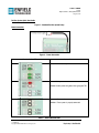
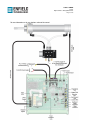
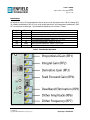
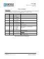
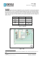
User’s Guide LS-C41 High Performance Analog PID Controller Page 11 of 25 Potentiometers All adjustments are by 25-turn potentiometers that are located on the right portion of the PCB (RP1 through RP7). The controller potentiometers (RP1-RP4) are on the middle-right and the valve-management potentiometers (RP5RP7) are located on the lower-right. The potentiometer adjustments are as shown in 7 below. Designation RP1 RP2 RP3 RP4 RP5 RP6 RP7 PCB Label Kp Ki Kd Kff DB DAmp DFrq Description Proportional Gain Adjustment – Range: 0.0 → 100.0 V/V Integral Gain Adjustment - Range: 0.0 → 100.0 V/V-s Derivative Gain Adjustment - Range: 0.0 → 1.0 V-s/V Feed-Forward Gain Adjustment - Range: 0.0 → 1.0 V/V Dead-Band Compensation – Range: 0% 25% Dither Amplitude Adjustment – Range: 0.0 to ±0.25A Dither Frequency Adjustment – Range: 10 Hz to 4 kHz Table 7 - Potentiometer Adjustments rev 20100312 Copyright © 2004-2010 Enfield Technologies, LLC Proprietary & Confidential