1
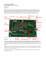
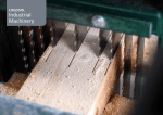
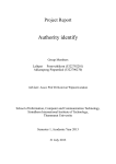
Christopher Bartram RF Design Microwave System Component Kit News 6 November 2012 Apologies for the delay in getting this month's newsletter out. I've started writing this on the day I returned home from the 2012 Scottish Microwave Roundtable at Burntisland on the Fife shore of the Firth of Forth. It was a strenuous weekend involving just under 1500km in the car, but the strains were countered by the excellence of the meeting, and the opportunity to meet a number of very old friends, and some new ones. My thanks to the organisers for making the weekend particularly memorable. Another reason for the delay is that I've been delivering prelaunch orders. Thanks to those who have waited with such patience. I've been very pleasantly surprised by the response to my project, and I am now working on more stock, and continuing the development of the other system components which I've previously mentioned. This includes the development of the 432MHz versions of the UDC10368 and SAT144P371 (UDC10368D and SAT432P371) which should be available in the next few days. The same reasons can be ascribed to my Web Site being overdue. I've blockedout some time in the next few days to get a very basic site up. A lot of the content is decided, and some is even written ... If you'd like to read the user manual for any of the products I'm making now, let me know, and I'll send you a PDF. The latest versions of these will be available on my Web Site once it's up. Discussions with a number of people, at Burntisland, the RSGB Convention, and by phone and email have pointed to other major projects which I might be interested in. I'm certainly beginning to look at other bands, but don't expect miracles! There are dangers in trying to do too much too quickly. I certainly don't want this project to go the way of some suppliers of equipment for the amateur microwave bands who have ranges which are far too big for them to maintain properly. There are too many people selling outdated equipment, and I don't want to be one of them! One product which a number of people liked the idea of at the GMRT is a drilled and finished box for the completed transverter. I'm looking at that. I may also consider making a wiring loom to avoid people having to find a suitable crimp tool for the KK connectors. Please tell me if you'd be interested. I'm beginning to develop the beginnings of some statistics regarding early production of the UDC10368. Generally, the results of most signal path parameters are within a dB or so of nominal across the production run. Even the image rejection, which is probably the most sensitive indicator of PCB problems has a standard deviation of less than 1.5dB. That is beginning to suggest that my choice of FR4 for a microstripline substrate at 10GHz really isn't as perverse as some people at first be thought! A copy of the new Overview/Pricelist is appended to this Newsletter. I'm afraid that some prices have had to rise as of 1 November. I'm trying very hard to make these system components affordable, but making small quantities of high technology RF/microwave electronics isn't cheap. Technical Note One of the attractions of the basic architecture which I've employed in the UDC10368 is that it is relatively simple to deal with bandplans which in the past would have involved a number of downconverters. The use of a synthesised local oscillator means that a switch between, say, 5760MHz for most conventional terrestrial and EME operation and 5840MHz for space operation, is straightforward. Other amateur microwave bands have similar problems: EME on 2.3GHz suffers a little from European activity being mainly on 2320MHz, the Americas being on 2304, the Japanese on 2424, and the VKs on 2301! However, even with a synthesised LO, a crystal oscillator is needed somewhere in the system. Perhaps even more than one … All crystals suffer from a timedependent drift in their characteristics due to the buildup of contamination on the crystal itself. High temperatures make ageing worse, as the crud (technical term!) deposits evaporate from the envelope and deposit themselves onto the quartz blank at a greater rate than at lower temperatures. Competent crystal manufacturers go to extreme lengths to ensure complete cleanliness in their assembly operations: plasma etching of the can is the norm amongst companies manufacturing for professional customers, but I have seen, what in retrospect were some awful practices amongst small crystal manufacturers in the UK. All of those manufacturers have now fallen by the wayside. I've heard it said – by a representative of a former UK crystal manufacturer, no less – that crystal ageing is a linear process. This was presumably a misunderstanding, even if it's not one I'd have expected from the person I was in conversation with … The reality is that after a short period of chaotic behaviour, which should be covered by the manufacturer's burnin procedures, crystal ageing moreorless follows a simple logarithmic law. This is used in a number of professional procurement specifications to provide a way of setting limits to the effect. One widely used specification is the US Military's MIL055310B. There a simple expression is used to approximate the ageing of a crystal. f(t) = A ln (B(t) + 1) +fo where A is the initial time and B(t) the elapsed time at the time of measurement, f o is the frequency drift at the initial time and f(t) the frequency at the time of measurement. So, a crystal which has aged, say, 0.5ppm in its first month of operation, will tend to age a total of only about 0.55ppm in the following year, and around a further 0.035ppm in the second year. Those figures are not untypical of good crystal performance at around 20°C. It is expected that once the initial burnin is completed, a good crystal should age less than 1ppm/year in it's first year, with the rate of ageing decreasing further with time. An ovened crystal is likely to age more quickly and to drift further. The voltage controlled temperature compensated crystal oscillator (VCTCXO) used in the SRF040R0L is designed to stay within 2.5ppm from 30° +70°C. This is a very great deal better than an uncompensated crystal oscillator, which even with a a very good crystal will not stay within ±2.5ppm over much more than about ±15° range around 20°C. Taking into account the shape of the temperature/frequency characteristic of an uncompensated crystal the rate of change of frequency with temperature is likely to be around 0.5ppm/°C at room temperature. The SRF040R0L TCXO performance is quoted as typically 0.1ppm/°C. One result of this is that the drift of the reference is less noticeable than an unlocked uncompensated crystal, and will compare to a crystal fitted with a PTC thermistor heater – without the extra ageing that operation at an elevated temperature implies. A more subtle reason for using a packaged TCXO is that the good ones usually have a remarkably linear , and reproducible, voltage tuning characteristic. This simplifies the design of circuitry to phaselock the TCXO to a frequency standard, allowing both the long term accuracy of the standard, and it's very good closein phase noise to be transferred to the TCXO, and thus to the VCO of the transverter synthesiser. So, why don't I just use 10MHz straight from a GPSDO or Rb 'standard' as a frequency reference for the synthesiser? There are two reasons. Firstly, in the design of a PLL synthesiser, it's always a good idea to make the phase comparison frequency as large as possible. This effectively minimises the amount of work which the phaselocked loop has to do to keep the VCO under tight control. Secondly, in the future, I will, where it's necessary, be using fractionalN synthesisers. While the fracN synth can provide surprisingly good performance if its problems are understood, it isn't a foolproof device. The major Achilles heel is that spurious products called 'IntegerN Boundary Spurs' are formed when the division ratio of the fractionalN engine is close to an integer multiple of the reference frequency. Although techniques exist for avoiding these, one of the best ways of achieving spurfree performance over a wide bandwidth is to maximise the reference frequency. 40MHz isn't a bad compromise between currently available VCTCXOs and synthesiser spurious, although it will be necessary to choose other frequencies for some bands. I think that's about it for this month. As ever if you want to know more, please email me. If you find or suspect an error here, I'd like to know! 73 Chris GW4DGU Christopher Bartram RF Design 16 Lon Ddewi, Meidrim, CARMARTHEN SA33 5QR phone: +44 1994 230626 mobile: +44 7545 094490 email: gw4dgu@chrisbartram.co.uk URL: www.chrisbartram.co.uk (not yet live, but keep trying ...) If you don't want to receive future copies of this Newsletter, please email me, and I'll take you off of my mailing list. I won't take offence! If you know someone who'd be interested in receiving a copy, please ask them to email me, and I'll add them to the list. Christopher Bartram RF Design Microwave System Components – an Overview 6 November 2012 Introduction These system components have been designed using 21st century technology to allow the construction of a high performance transverters and other units for the microwave amateur bands. These PCBbased assembled system components will make the amateur microwave bands accessible to radio amateurs who lack the ability, facilities, or spare time to build modern microwave equipment from scratch. This note provides background information on some of the initial units which are either in, or close to, production. Any performance figures quoted here are, where possible, based on measurements of early production units. ICP Port PIC Synthesiser Reference +8V T/R Input Reference Sequencer SMA O/P Bulk Regulator T/R Control 12V I/P Uwave I/O SMA IF I/O SMA Fig.1 UDC10368c The Basics IF 90º Hybrid Mixers 10GHz 90º IF Preamps Hybrid The system components, with the exception of filters and dish feeds, are designed as PCBbased modules of standardised sizes (~ 93 x 68 and 51 x 68mm) using modern surfacemount parts. Where necessary multilayer PCB technology is employed. Rather than use the tired old technologies of the 1980s these system components represent a fresh approach to the design of microwave equipment for radio amateurs, allowing a progression from a very basic, low power up/down converter, all the way to a highly capable system. Integral screening is provided by the PCB design and chemically milled 5sided boxes. This will usually provide adequate screening without the need to use further enclosures, although the use of highpowers at the IF will require additional attention. The chemically etched screen is not shown in the photograph. RF and microwave interconnections are made using SMA connectors, while the DC and control interfaces are via 2.54mm pitch Molex KK type connectors. Christopher Bartram RF Design 10GHz Transverter Modules: Preliminary Information Page 2 of 4 Initial Products UDC10368C – imagereject up/down converter The first product to become available was a synthesised lowpower up/downconverter from and to 144 and 10368MHz. This uses an imagereject topology to reduce spurious outputs on transmit to acceptable levels when operating without external amplifiers. One reason for choosing the imagereject approach has been that two UDC s operating standalone, in conjunction with 60cm dishes, should be capable of communicating over any lineofsight path within the UK. (1) The UDC10368C employs a highperformance singlechip microwave frequency synthesiser operating at 5112.0MHz as its local oscillator. The mixers used operate with the local oscillator at half the usual frequency. This has a number of advantages regarding spurious generation, and also results in some circuit simplification. The mixers are combined at microwave frequencies via printed microstripline networks and at 144MHz by an L/C hybrid combiner. On receive, each mixer has its own 144MHz preamplifier, using a SiGe transistor: this has been designed for excellent amplitude and phase stability as well as a low noise figure. A noise figure of approximately 13dB and an output power at 1dB gain compression of 10dBm can be expected from the standalone board. Small signal sensitivity is not compromised by the use of frequency synthesis, despite illinformed notes published in some places! The UDC10368 can also be supplied to special order for 10368 – 432MHz, or 10450MHz 145MHz operation, and for use as a DATV up/downconverter from 70 or 435MHz, please contact me for further details. Outline Performance Figures: P(1dB): Spurious outputs: image (10080MHz): local oscillator (10224MHz): half local oscillator (5112MHz): 10dBm <30dBm 20dBm 28dBm Receiver Gain: Receiver Noise Figure >2dB 13dB Price: £149.90 Availability: exstock to 4 weeks SRF040R0L – lockable 40MHz frequency reference The microwave frequency synthesiser employed by the UDC10368C requires a clean, stable frequency reference at 40, 80, or 96MHz. The SRF040R0L is based around a packaged 40MHz temperature compensated crystal oscillator (TCXO), and has adequate stability for casual SSB/CW operation. In order to improve the closein performance and frequency stability to a level suitable for advanced applications, such as JT4 and even JT65, the SRF040R0L has a linkselectable phaselocking circuit intended for use with 10MHz references such as GPSDOs, and Rubidiumlocked sources. Price: £49.90 Availability: exstock to 4 weeks FBP10368W40 – 10368MHz 40MHz bandpass filter To use amplifiers in the transmit path of a transverter based on the UDC10368, it's necessary to add bandpass filtering in order to reduce the transmitted spurious to an acceptable level. A bandpass filter will also reduce the susceptibility of the receive path to out ofband interference. The FBP10368W60 is a a twopole bandpass filter using a dualmode topology in circular waveguide. The insertion loss is ~1.5dB at 10368MHz, with an associated bandwidth of ~30MHz and returnloss of ~18dB. At 10224MHz the filter has an insertion loss of ~40dB, and at 10080MHz, this increases to about 65 dB. Price: £45.90 Availability: exstock to 4weeks Christopher Bartram RF Design 10GHz Transverter Modules: Preliminary Information Page 3 of 4 SAT144P371 – switched attenuator As the UDC10368C requires only 20mW drive on transmit, some form of attenuator is required between typical transceivers and the unit. The SAT144P5 is a variable attenuator which can be driven with between 0.1 and 5W, and set to an output level of 10mW. The attenuator is switchedin on transmit under control of the sequencer in the UDC10368C. On receive, the signal will pass through with less than 1dB loss. Although designed for general purpose use with CBRFD transverter boards, the SAT144P371 also has a dedicated FT817 interface. Introductory Price: £44.90 Availability: exstock to 4weeks ADF10368F0R7 – dish feed To efficiently feed an offset dish, such as those used for satellite TV, requires a feed horn which is matched to the focal length/diameter ratio of the dish. While older designs, such as those of the late Dick Turrin, W2IMU, are available, they are often difficult to build, while some amateur realisations, due to attempts to use available materials, fail to work properly. The ADF10368F0R7 is a compact feedhorn with an inbuilt coax to waveguide transition. It uses the a step in the circular waveguide to launch two waveguide modes. At the mouth of the horn, the two modes combine out of phase at the edge, resulting in cancellation of any currents flowing around the edge of the horn. It is these currents, which if allowed to exist, cause the generation of unwanted sidelobes. The result, when the horn is used with a suitable dish, is an antenna which has excellent aperture efficiency. Price: £69.90 Availability: exstock to four weeks On the Stocks As the range of system components described here is very new, it will change frequently! The units described in this section are amongst those in active development. ART10368P15 In order to increase the output power of the UDC10368 and it's sensitivity to levels where obstructed paths with greater losses can be be worked, the ART10368P15 contains a 30mW power amplifier, and a 2dB noise figure, 11dB gain receive path amplifier on a 63 x 51mm PCB. The transmit power level should be adequate to drive a variety of high power amplifiers, including a design from CBRFD, while the receiver sensitivity achieved by the receive path amplifier will be adequate as a second stage for a high performance LNA. Availabiilty: late 2012. ATX10368P33 This will be a 2.5W amplifier using a MMIC power device. It will also contain a lownoise amplifier with a noise figure of about 1.2dB. Availability: early 2013 Other bands? Higher Powers? Of course! 6cm may be next on the list, or will I succumb to 1296? There are dangers in trying to do too much, too quickly. I don't want this project to go the way of some suppliers of microwave amateur radio equipment (no names ...) who have ranges which are too big for them to maintain properly, and so endup trying to sell a lot of outdated designs! Christopher Bartram RF Design 10GHz Transverter Modules: Preliminary Information Page 4 of 4 Interested? For further information, and to get on the mailing list, please email Chris Bartram, GW4DGU <gw4dgu@chrisbartram.co.uk> Accuracy: I do my best to maintain accuracy in all CBRFD's documentation. If you believe that you've found an error, please tell me. I'd like to believe I'm perfect, but I know otherwise! Christopher Bartram RF Design, 16 Lôn Ddewi, Meidrim, CARMARTHEN, Wales. SA33 5QR phone: 01994 230626. email: gw4dgu@chrisbartram.co.uk web: www.chrisbartram.co.uk (not yet up)