1
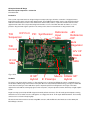
Christopher Bartram RF Design Microwave System Components – an Overview 6 November 2012 Introduction These system components have been designed using 21st century technology to allow the construction of a high performance transverters and other units for the microwave amateur bands. These PCBbased assembled system components will make the amateur microwave bands accessible to radio amateurs who lack the ability, facilities, or spare time to build modern microwave equipment from scratch. This note provides background information on some of the initial units which are either in, or close to, production. Any performance figures quoted here are, where possible, based on measurements of early production units. ICP Port PIC Synthesiser Reference +8V T/R Input Reference Sequencer SMA O/P Bulk Regulator T/R Control 12V I/P Uwave I/O SMA IF I/O SMA Fig.1 UDC10368c The Basics IF 90º Hybrid Mixers 10GHz 90º IF Preamps Hybrid The system components, with the exception of filters and dish feeds, are designed as PCBbased modules of standardised sizes (~ 93 x 68 and 51 x 68mm) using modern surfacemount parts. Where necessary multilayer PCB technology is employed. Rather than use the tired old technologies of the 1980s these system components represent a fresh approach to the design of microwave equipment for radio amateurs, allowing a progression from a very basic, low power up/down converter, all the way to a highly capable system. Integral screening is provided by the PCB design and chemically milled 5sided boxes. This will usually provide adequate screening without the need to use further enclosures, although the use of highpowers at the IF will require additional attention. The chemically etched screen is not shown in the photograph. RF and microwave interconnections are made using SMA connectors, while the DC and control interfaces are via 2.54mm pitch Molex KK type connectors.