1
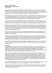
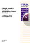
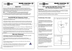
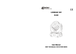
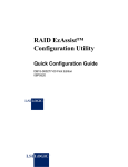
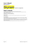
StorageSmart™ - ProFibre Storage Array
RAID Controller Unit - DF1100R
Storage Expansion Unit - DF1100J
IBM
Operator’s Guide
SA18-7716-00
StorageSmart™ - ProFibre Storage Array
RAID Controller Unit - DF1100R
Storage Expansion Unit - DF1100J
IBM
Operator’s Guide
SA18-7716-00
Note!
Before using this information and the product it supports, read the information in “Safety Notices” on page v and “Notices”
on page 33.
First Edition (February 2001)
Visit the IBM ProFibre web page at: http://www.ibm.com/storage/profibre
© Copyright International Business Machines Corporation 2001. All rights reserved.
US Government Users Restricted Rights – Use, duplication or disclosure restricted by GSA ADP Schedule Contract
with IBM Corp.
Contents
Safety Notices . . . . . . . . . . . . v
Acoustic Noise Declaration .
Electrostatic Discharge (ESD) .
.
.
.
.
.
.
.
.
.
.
.
.
.
.
. v
. v
About This Book . . . . . . . . . . vii
If You Need More Information . . . . . . . . vii
Numbering Convention . . . . . . . . . . viii
Chapter 1. Introduction . . . . . . . . 1
The ProFibre Storage Array . . . . . . . . . 2
Controls and Lights . . . . . . . . . . . . 3
Disk Drive Modules . . . . . . . . . . . 4
Fan-and-Power-Supply Assemblies . . . . . . 5
RAID FF Cards . . . . . . . . . . . . 7
FC-AL Interface Cards . . . . . . . . . . 8
Switch Card . . . . . . . . . . . . . 9
Identifying Disk Drive Modules . . . . . . . 11
Chapter 2. Adding Disk Drive Modules
Before Adding a Disk Drive Module .
To Add a Disk Drive Module . . .
.
.
.
.
.
.
.
.
13
. 14
. 14
Preparing to Exchange Parts . . . . . . . .
Exchanging Disk Drive Modules . . . . . .
Before Exchanging a Disk Drive Module. . .
To Exchange a Disk Drive Module. . . . .
Exchanging a Fan-and-Power-Supply Assembly .
Before Exchanging a Fan-and-Power-Supply
Assembly . . . . . . . . . . . . .
To Exchange a Fan-and-Power-Supply Assembly
.
.
.
.
.
17
17
18
18
21
. 22
22
Chapter 4. Reporting Problems . . . . 31
Notices . . . . . . . . . . . . . . 33
General. . . . . . . . . . . . .
Submitting Comments about this Publication
Performance Data . . . . . . . . .
Softcopy Authorization . . . . . . .
IBM License Agreement for Machine Code .
Trademarks . . . . . . . . . . .
.
.
.
.
.
.
.
.
.
.
.
.
.
.
.
.
.
.
33
33
34
34
34
35
Index . . . . . . . . . . . . . . . 37
Chapter 3. Exchanging Disk Drive
Modules and Fan-and-Power-Supply
Assemblies . . . . . . . . . . . . . 17
© Copyright IBM Corp. 2001
iii
iv
ProFibre Storage Array: Operator’s Guide
Safety Notices
A danger notice indicates the presence of a hazard that has the potential of causing
death or serious injury.
A danger notice appears on page 27.
A caution notice indicates the presence of a hazard that has the potential of causing
moderate or minor personal injury.
Caution notices appear on pages 9, 1, 23, and 25.
An attention notice indicates an action that could cause damage to a program,
device, system, or data.
Acoustic Noise Declaration
The equivalent continuous A-weighted sound pressure level at the bystander’s
position measured for a rack-mounted unit of a ProFibre Storage Array does not
exceed 68 dB(A). This level has been measured under the following conditions:
v The unit of the ProFibre Storage Array had 10 disk drive modules installed.
v The unit of the ProFibre Storage Array was installed in a rack with the bottom
of the unit at EIA position 17.
v The remainder of the rack was filled with units to which power was not
connected.
These levels were measured using a procedure in accordance with ISO standard
DIS7779, Measurement of Airborne Noise Emitted by Computer and Business Equipment.
The equipment was installed and operated as described in Appendix C.8 of that
standard.
Electrostatic Discharge (ESD)
When you handle any computer parts, take these precautions to avoid ESD
damage:
v Limit your movement. Movement can cause static electricity to build up
around you.
v Always touch computer parts carefully. Hold adapters and memory-modules
by their edges. Never touch any exposed circuits. Prevent other people from
touching computer parts.
v Before you install a new part, touch the static-protective package that contains
the part against an unpainted metal part of the using system or the ProFibre
Storage Array unit for at least two seconds. This action reduces static
electricity in the package and in your body.
v Remove the part from its package and, if possible, install it directly into the
unit of the ProFibre Storage Array without putting the part down. If you need
to put the part down, first place the static-protective package that contained
the part onto a smooth, level surface, then place the part onto the
static-protective package. Do not place the part onto any metal surface.
© Copyright IBM Corp. 2001
v
CAUTION:
Do not try to replace and/or exchange the Ni-MH rechargeable battery pack
integral to the Battery Backup Unit (BBU) assembly.
The Ni-MH battery pack contains small amounts of harmful substances.
v Keep the BBU away from fire
v Do not expose the BBU to water or rain
v Do not attempt to disassemble the BBU
v Do not short circuit the BBU
v Keep away from children
v Do not put the BBU into rubbish that is put into landfill sites. When
discarding the BBU, observe local ordinances, regulations and your company’s
safety standards for disposal
vi
ProFibre Storage Array: Operator’s Guide
About This Book
This book gives operating information for the ProFibre Storage Array. This book is
for people who operate a system that has one or more ProFibre Storage Arrays
connected to it.
Chapter 1 describes the ProFibre Storage Array, its controls, and how to use them:
v The lights and switches on the units of the ProFibre Storage Array
v How to identify units of the ProFibre Storage Array and the disk drives within
them
v How to install additional disk drives into the ProFibre Storage Array
Chapter 2 describes how to add disk drive modules to a ProFibre Storage Array
that is already installed as part of your system.
Chapter 3 describes how to exchange failed components of your ProFibre Storage
Array.
v How to change a faulty disk drive module
v How to change a faulty fan-and-power-supply assembly
Chapter 4 provides information for reporting problems with your ProFibre Storage
Array.
Throughout this book, service representative means a person who has been
authorized by your organization to maintain your ProFibre Storage Array.
An index is provided at the back of this book.
If You Need More Information
Other books that you might need are:
v StorageSmart - ProFibre Storage Array, RAID Controller Unit - DF1100R, Storage
Expansion Unit - DF1100J: Hardware Technical Information, SA18-7714
v StorageSmart - ProFibre Storage Array, RAID Controller Unit - DF1100R, Storage
Expansion Unit - DF1100J: Installation Guide, GA18-7715
v StorageSmart - ProFibre Storage Array, RAID Controller Unit - DF1100R, Storage
Expansion Unit - DF1100J: Service Guide, GY18-2409
v StorageSmart - ProFibre Storage Array: Translated Safety Notices, SA33-3308
v StorageSmart - ProFibre Storage Array: Electromagnetic Compatibility Statements,
GA67-0040
v SANArray Manager™ Client Software for Mylex External Disk Array Controllers:
Installation and User Manual, 08P4179
v The Operator Guide, or equivalent, for your system
v The User’s Guide, or equivalent, for your host-system Fibre Channel attachment
(for example, your Fibre Channel adapter)
v The Site and Hardware Planning Information, or equivalent, for your system
v The Problem Solving Guide and Reference, or equivalent, for your system.
© Copyright IBM Corp. 2001
vii
Numbering Convention
In this book:
KB means 1 000 bytes.
MB means 1 000 000 bytes.
GB means 1 000 000 000 bytes.
viii
ProFibre Storage Array: Operator’s Guide
Chapter 1. Introduction
This section describes the ProFibre Storage Arrays, their controls, and how to use
them.
Important: The installation of this product is a customer responsibility.
Attention: Damage as a result of improper handling might cancel your equipment
warranty.
CAUTION:
Do not attempt to lift a unit of a ProFibre Storage Array by yourself. Ask
another person to help you.
CAUTION:
A rack-mounted unit weighs up to 38.5 kg (85 lb) with disk drive modules
installed. Do not attempt to lift the unit into the rack unless all the disk drive
modules have been removed.
CAUTION:
Do not use the handles on the fan-and-power-supply to help carry the unit.
© Copyright IBM Corp. 2001
1
The ProFibre Storage Array
The ProFibre Storage Array comprises a controller unit and up to seven expansion
units.
Each unit in a ProFibre Storage Array is 3 EIA units high and is suitable for
mounting in an industry standard (EIA) 19-inch rack.
Figure 1. Rack-Mounted Units.
The top diagram shows the front of either a controller unit or an expansion unit; the center
diagram shows the back of a controller unit; the bottom diagram shows the back of an
expansion unit.
At the front of a controller unit or expansion unit are ten device slots«1¬. Each slot
must contain either an FC-AL disk drive module, or a dummy module. (A dummy
module is required to maintain airflow for proper cooling of the enclosure.) Each
disk drive module connects to a backplane that is mounted vertically across the
unit. At least one disk drive module must be present in every controller or
expansion unit.
2
ProFibre Storage Array: Operator’s Guide
On the back of the backplane of a controller unit are connectors for two
fan-and-power-supply assemblies«2¬, two RAID FF cards«3¬, and a switch card«4¬.
An expansion unit has connectors for two FC-AL Interface Cards«5¬ instead of two
RAID FF cards«3¬.
Each unit has two fan-and-power-supply assemblies «2¬. If one power supply fails,
power for the unit continues to be supplied by the other power supply.
A RAID FF card «3¬ provides two Fibre Channel connectors. The connector on the
left is used for connection to a host computer, and the connector on the right can
be used to connect to an expansion unit.
A RAID FF card also contains logic that provides:
v Control of up to 80 FC-AL disk drives in up to eight ProFibre Storage Array
units (one controller unit and up to seven expansion units)
v Support for RAID levels 0, 1, 3, 5 and 0+1
v Support for data cache up to 512 MB
v Collection and reporting of enclosure services data using the ANSI SCSI
Enclosure Services (SES) protocol
More information about the RAID FF card can be found on page 7.
FC-AL interface cards «5¬ in an expansion unit are used to connect the expansion
unit to a controller unit or another expansion unit. They also provide support for
SES. More information about the FC-AL interface card can be found on page 8.
The switch card «4¬: There are two types of switch cards available; one for the
controller unit and one for the expansion unit. A controller unit must contain a
switch card with a Battery Backup Unit (BBU). (The BBU provides up to 72 hours
of data cache retention for the RAID FF cards in the event of there being a sudden
loss of power to the controller unit.) An expansion unit must contain a switch card
without a BBU. More information about the switch card can be found on page 9.
Controls and Lights
This section describes the switches and lights on a unit in a ProFibre Storage Array.
A unit in a ProFibre Storage Array has no main power switch. However, each
fan-and-power-supply assembly has an On/Standby switch.
During normal operations, you do not need to check the lights on the unit.
Chapter 1. Introduction
3
Figure 2. Indicator Lights
The following lights are on the front of the units.
Unit Power light «1¬
The Unit Power light, which is green, comes on continuously when power
is being supplied to the unit by one or both of the fan-and-power-supply
assemblies within the unit.
Check light «2¬
The Check light, which is amber, comes on if a failure occurs in the unit
and an active connection to the unit exists.
Note that a unit of the ProFibre Storage Array should be able to continue
operating correctly even when the failure of a single part has been
detected.
Disk Drive Modules
The lights on disk drive modules that are installed in a unit of a rack-mounted
ProFibre Storage Array are visible at the front of the unit.
Figure 3. Disk Drive Module Lights
Each disk drive module has two lights:
«1¬Activity light
The Activity light, which is green, shows the following conditions:
4
ProFibre Storage Array: Operator’s Guide
Off
The disk drive module is not powered on.
On
The disk drive module is ready but not active.
Flashing
This disk drive module is active with a command in progress.
«2¬Check light
The Check light, which is amber, shows the following conditions:
Off
Normal operating condition.
Permanently On
The drive has reported a Predictive Failure Analysis® (PFA) error
(this error indicates that the disk drive has had an excessive
number of internally recovered errors),
OR the disk drive is faulty (this is an SES function).
Flashing (0.5 seconds on, 0.5 seconds off)
The data on this disk drive is being rebuilt using data on other
disk drives in the same array. Flashing of the light is controlled by
a SES function.
Fan-and-Power-Supply Assemblies
Two fan-and-power-supply assemblies «1¬ are installed in the back of a unit in the
ProFibre Storage Array.
mef30106
The power switch and lights are visible at the back of the unit.
Figure 4. Fan-and-Power-Supply Assemblies
Note: The diagram shows controller units. The fan-and-power-supply assemblies
are in the same position in expansion units.
Chapter 1. Introduction
5
Figure 5. Fan-and-Power-Supply Assembly Lights and Switch
A fan-and-power-supply assembly has the following lights and switch:
AC PWR light «1¬
The AC PWR light, which is green, comes on when the mainline power
supply is connected to the fan-and-power-supply assembly.
DC PWR light «2¬
The DC PWR light, which is green, comes on when this
fan-and-power-supply assembly is supplying power to the ProFibre
Storage Array unit.
CHK light «3¬
The CHK light, which is amber, indicates a failure in the
fan-and-power-supply assembly.
Note: This light is always off when the DC On/Standby switch is set to
standby.
DC On/Standby switch «4¬
The DC On/Standby switch connects dc electrical power from the
fan-and-power-supply assembly to the disk drives and other components
in the ProFibre Storage Array unit. This switch must be set to on for the
fan-and-power-supply unit to start.
If the DC On/Standby switch on either of the two fan-and-power-supply
assemblies is set to on, power in the ProFibre Storage Array unit is
switched on automatically if all of the following conditions exist:
v Input power to the ProFibre Storage Array is present.
v The fan-and-power-supply assembly is fully inserted into its slot.
6
ProFibre Storage Array: Operator’s Guide
RAID FF Cards
mef30109
Two RAID FF «1¬ cards are installed in the back of a ProFibre Storage Array
Controller Unit (see Figure 6
Figure 6. RAID FF Card Assemblies
A RAID FF card has the following lights:
Figure 7. RAID FF Card Assembly Lights
Power light «1¬
The Power light, which is green, is lit when dc power is applied to the
RAID FF card.
DRIVE FC Active light «2¬
The DRIVE FC Active light, which is green, is lit when there is any activity
on the Fibre Channel connection to any disk drive.
HOST FC Active light «3¬
The HOST FC Active light, which is green, is lit when there is any activity
on the Fibre Channel connection to the host computer.
Chapter 1. Introduction
7
HOST FC Status light «4¬
This Status light, which is amber, is lit when there is no valid Fibre
Channel connection through the HOST port, or when the port is inactive
while it is waiting for failover.
OUT FC Status light «5¬
This Status light, which is amber, is lit when there is no valid Fibre
Channel connection through the OUT port, or when the port is inactive
while it is waiting for failover.
Card Fault light «6¬
The Card Fault light, which is amber, is lit when there is a fault on the
RAID FF card or during boot up of the RAID FF card.
FC-AL Interface Cards
mef30117
Two FC-AL interface «1¬cards are installed in the back of a ProFibre Storage Array
Expansion Unit.
Figure 8. FC-AL Interface Card Assemblies
An FC-AL interface card has the following lights:
Figure 9. FC-AL Interface Card Assembly Lights
Status lights «1¬
There are two amber Status lights. The one on the left is lit when there is
no active Fibre Channel connection to the IN port. The one on the right is
lit when there is no active Fibre Channel connection to the OUT port.
8
ProFibre Storage Array: Operator’s Guide
Power light «2¬
The green Power light is lit when the voltage is correct.
Card Fault light «3¬
The amber Card Fault light is lit when an error condition has been
detected.
Switch Card
mef30111
A switch card«1¬is installed in the back of a unit of the ProFibre Storage Array.
Figure 10. Switch Cards
Note: The diagram shows a controller unit. A switch card is installed in the same
place in an expansion unit.
The switch card in the controller unit has a BBU that provides up to 72 hours of
data cache retention in the event of a sudden loss of power in the unit.
CAUTION:
Do not try to replace and/or exchange the Ni-MH rechargeable battery pack
integral to the Battery Backup Unit (BBU) assembly.
The Ni-MH battery pack contains small amounts of harmful substances.
v Keep the BBU away from fire
v
v
v
v
Do not expose the BBU to water or rain
Do not attempt to disassemble the BBU
Do not short circuit the BBU
Keep away from children
v Do not put the BBU into rubbish that is put into landfill sites. When
discarding the BBU, observe local ordinances, regulations and your company’s
safety standards for disposal
Chapter 1. Introduction
9
Figure 11. Switch Card (with or without BBU)
The switch card contains two separate switches:
FC-AL Address switch «5¬
This switch can be set to a value between 0 and 7. It controls the FC-AL
addresses used by the ProFibre Storage Array. For example, if the switch is
set to 5, the FC-AL address of the disks in slots 1 to 10 are then 50 to 59
(hexadecimal). In this case, the address of the enclosure services is 5A
(hexadecimal).
Note: Each enclosure in the ProFibre Storage Array must have a unique
switch setting. Switch settings of 8 or 9 are not supported and
should not be used; however, if selected are treated as 7. If switch
card settings 7, 8, and 9 are used in the same system, unique FC-AL
addresses cannot be assigned to the disk drive slots.
Below the FC-AL Address switch is a 4-bit dip switch called the option switch.
Option Switch
v Switch 1—Orientation Switch: «1¬ This switch should be set to ON
indicating a rack-mounted unit.
v Switch 2 — Not used «2¬: This switch should be set OFF.
v Switch 3 — Not used «3¬: This switch should be set OFF.
v Switch 4 — Not used «4¬: This switch should be set OFF.
10
ProFibre Storage Array: Operator’s Guide
Identifying Disk Drive Modules
You can identify a disk drive module by the serial number that appears on a label
«1¬ on the front of the module:
Figure 12. Disk Drive Module Label
This label also shows the capacity of the disk drive.
Each disk drive module also has a FC-AL address that is related to its position in
the ProFibre Storage Array unit.
The addresses used are S0 to S9 (hex) where S is the setting of the address switch
on the switch card. These addresses are assigned, in sequence, from left to right.
Chapter 1. Introduction
11
12
ProFibre Storage Array: Operator’s Guide
Chapter 2. Adding Disk Drive Modules
This chapter describes how to add disk drive modules to a unit in a ProFibre
Storage Array that is already installed as part of your system.
You can do this only if:
1. You are authorized by your organization.
2. You have the correct disk drive module. Refer to Figure 13. This disk drive
module has, at the front, a handle «1¬ that can be pulled upward to open. The
capacity of a disk drive module is shown on a label «2¬ at the front of the disk
drive module. The label is shown in more detail in Figure 12 on page 11.
Figure 13. Disk Drive Module Handle and Label
Attention: Disk drive modules are fragile. Handle them with care. Keep them well
away from strong magnetic fields.
You do not need to remove power from the unit when adding a disk drive
module.
After you have added a disk drive module to the unit, you must add it into your
system software configuration by using the system programs.
Refer to the SANArray Manager Client Software for Mylex External Disk Array
Controllers: Installation and User Manual for guidance on how to do this.
© Copyright IBM Corp. 2001
13
Before Adding a Disk Drive Module
Identify the slot for the new disk drive module by using the configuration
planning information for your system. A dummy disk drive module should be in
the slot. See Figure 14.
Figure 14. Dummy Disk Drive Module
To Add a Disk Drive Module
1. Pull the dummy module out of the unit.
Figure 15. Removing a Dummy Module
Attention: The fans might increase in speed. Do not leave the slot empty for
more than 30 minutes; if you do, the unit, and the disk drive modules that it
contains, might overheat and be damaged.
14
ProFibre Storage Array: Operator’s Guide
2. With one hand giving support to the base of the disk drive module and the
other hand holding the handle «1¬, insert the module and push it into the slot.
When the handle touches the front surface of the unit, the module stops. Note
that the module is not yet fully inserted.
Figure 16. Adding a Disk Drive Module
3. While continuing to push the disk drive module into the slot, slowly close the
handle «1¬ until it stops with a click. This action fully inserts the module into
the connector at the back of the slot.
Attention: The fans might decrease in speed.
Figure 17. Closing the Handle of a Disk Drive Module
Chapter 2. Adding Disk Drive Modules
15
4. Verify that the disk drive module that you have just installed is aligned with
the sides of the unit, and that no gap exists between this module and the
modules that are next to it.
Verify also that the front edge of this disk drive module aligns with the front
edges of the modules next to it.
If the disk drive module is not correctly aligned, remove it (see step 1 on
page 18) and reinstall it (steps 2 through 3 above).
5. The green Activity «1¬ light comes on and then goes off. If the amber Check
«2¬ light comes on, verify that the new disk drive module has been correctly
installed. If it has been correctly installed, refer to the SANArray Manager Client
Software for Mylex External Disk Array Controllers: Installation and User Manual for
guidance on how to obtain information about the problem.
Figure 18. Disk Drive Module Lights
6. Add the new disk drive module into your system software configuration, using
the system programs.
Refer to the SANArray Manager Client Software for Mylex External Disk Array
Controllers: Installation and User Manual for guidance on how to do this.
16
ProFibre Storage Array: Operator’s Guide
Chapter 3. Exchanging Disk Drive Modules and
Fan-and-Power-Supply Assemblies
This chapter describes what to do if you need to exchange a disk drive module or
a fan-and-power-supply assembly.
If you need to exchange a RAID FF card, a FC-AL interface card, or a switch card,
refer to the StorageSmart - ProFibre Storage Array, RAID Controller Unit - DF1100R,
Storage Expansion Unit - DF1100J: Service Guide.
Preparing to Exchange Parts
Refer to the SANArray Manager Client Software for Mylex External Disk Array
Controllers: Installation and User Manual and the StorageSmart - ProFibre Storage
Array, RAID Controller Unit - DF1100R, Storage Expansion Unit - DF1100J: Service
Guide for information about determining the cause of a problem.
Exchanging Disk Drive Modules
You can exchange a faulty disk drive module only if:
v You are authorized by your organization.
v You have a correct replacement disk drive module.
Only disk drive modules that have a latch behind a handle «1¬ that you pull
upward to open, can be installed in the units of a ProFibre Storage Array. There
is a label «2¬ at the front of each disk drive module. This label indicates that the
disk drive module is an FC-AL disk drive module. It also shows the capacity of
the disk drive module. See Figure 19.
Figure 19. Disk Drive Module Handle and Capacity
The replacement disk drive module should have at least the capacity of the disk
drive module being replaced.
© Copyright IBM Corp. 2001
17
Attention:
v Disk drive modules are fragile. Handle them with care. Keep them well away
from strong magnetic fields.
v Any slot that has no disk drive module installed must contain a dummy disk
drive module. The dummy module ensures that the correct airflow is
maintained around the disk drive modules in the other slots. If a slot remains
empty, overheating may occur.
You do not need to remove power from the unit when exchanging a disk drive
module.
Before Exchanging a Disk Drive Module
1. Check the lights on this disk drive module. (“Disk Drive Modules” on page 4
describes where these are, and how to see them.)
If the Check light is not on, you cannot exchange the disk drive module; call
your service representative and report the problem.
If the Check light is on, exchange the disk drive module for a new one using
the procedure described in the following section.
To Exchange a Disk Drive Module
1. Pull upward on the latch «1¬ and pull the handle «2¬ of the failing disk drive
outward. This action disconnects the disk drive from the connector at the back
of the module and partially moves the module out of the slot.
Figure 20. Opening the Disk Drive Module Handle
2. Attention: Wait for twenty seconds to allow time for the disk drive motor to
stop.
3. Carefully pull the module out of the unit. Support the module with your other
hand as you take it out of the unit.
18
ProFibre Storage Array: Operator’s Guide
Figure 21. Removing a Disk Drive Module
Attention: The fan speed may increase. Do not leave the slot empty for more
than 30 minutes; if you do, the unit, and the disk drive modules, may overheat
and be damaged.
4. With one hand giving support to the base of the replacement module and the
other hand holding the handle «1¬, insert the module and push it into the slot.
When the handle touches the front surface of the unit, the module stops. Note
that the disk drive module is not yet fully inserted.
Figure 22. Inserting a Disk Drive Module
5. While continuing to push the disk drive module into the slot, slowly close the
handle «1¬ until it stops with a click. This action fully inserts the module into
the connector at the back of the slot.
Chapter 3. Exchanging Disk Drive Modules and Fan-and-Power-Supply Assemblies
19
Attention: The speed of the fans may decrease.
Figure 23. Closing the Handle
6. Verify that the disk drive module that you have just installed is aligned with
the sides of the unit and that no gap exists between this module and the
modules that are next to it.
Verify also that the front edge of this disk drive module aligns with the front
edges of the modules next to it.
If the disk drive module is not correctly aligned, remove it (see 1 on page 18)
and reinstall it (steps 4 through 6 above).
7. The green Activity «1¬ light and the amber Check «2¬ light both come on and
then go out. If the Check light stays on, verify that the new disk drive module
has been correctly installed. If it has been correctly installed, refer to the
SANArray Manager Client Software for Mylex External Disk Array Controllers:
Installation and User Manual, GA18-7717 for guidance on how to obtain
information about the problem.
20
ProFibre Storage Array: Operator’s Guide
Figure 24. Disk Drive Module Lights
8. Restore the disk drive module into your system, using the system programs.
Exchanging a Fan-and-Power-Supply Assembly
You can exchange a faulty fan-and-power-supply assembly if:
v You have a correct spare fan-and-power-supply assembly and,
v Another fan-and-power-supply assembly is still present in this unit.
Figure 25. A Fan-and-Power-Supply Assembly
You do not need to remove power from the other fan-and-power-supply assembly
in this unit when exchanging a fan-and-power-supply assembly.
Chapter 3. Exchanging Disk Drive Modules and Fan-and-Power-Supply Assemblies
21
Before Exchanging a Fan-and-Power-Supply Assembly
Check the lights on this fan-and-power-supply assembly (see: “Fan-and-PowerSupply Assemblies” on page 5). Ensure that the DC On/Standby switch is on.
Attention: If the Check light is not on, do not exchange the power-supply
assembly; call your service representative and report the problem.
If the Check light is on, exchange the fan-and-power-supply assembly by using the
procedure in the following section.
To Exchange a Fan-and-Power-Supply Assembly
1. Set the On/Standby switch«1¬ on the failed fan-and-power-supply assembly to
Standby.
2
1
Figure 26. Fan-and-Power-Supply On/Standby Switch
Note: The fan-and-power-supply DC PWR light«2¬ may stay on for a short
time. Wait until it is off before you go to the next step.
22
ProFibre Storage Array: Operator’s Guide
2. Unplug the mainline power cable from the failing fan-and-power-supply
assembly.
1
Figure 27. Unplugging the Mainline Power Cable
CAUTION:
Ensure that the mainline power cable has been removed from the failing
fan-and-power-supply assembly, and the AC PWR light«1¬ is off, before
continuing.
Chapter 3. Exchanging Disk Drive Modules and Fan-and-Power-Supply Assemblies
23
3. Unscrew the two thumbscrews on the fan-and-power-supply assembly.
Figure 28. Unscrewing the Thumbscrews on the Fan-and-Power-Supply Assembly
24
ProFibre Storage Array: Operator’s Guide
4. Pull the fan-and-power-supply assembly from the unit.
Attention: The speed of the other fan in the unit may increase.
Figure 29. Removing the Fan-and-Power-Supply Assembly
Attention: Do not leave the space empty for more than 30 minutes; if you do,
the unit, and the disk drive modules may overheat and be damaged.
CAUTION:
Do not insert hands or tools into the empty space where the
fan-and-power-supply assembly was.
Chapter 3. Exchanging Disk Drive Modules and Fan-and-Power-Supply Assemblies
25
5. Push the replacement fan-and-power-supply assembly fully into the unit.
Attention: The speed of the other fan in the unit may decrease.
Figure 30. Inserting a Replacement Fan-and-Power-Supply Assembly
6. Tighten the two thumbscrews by turning them clockwise.
Figure 31. Tightening the Screws on a Fan-and-Power-Supply Assembly
26
ProFibre Storage Array: Operator’s Guide
7. Plug the mainline power cable into the new fan-and-power-supply assembly.
Ensure that the AC PWR light«1¬ comes on.
DANGER
Do not plug the power supply cord into the fan-and-power-supply
assembly until the unit has been completely installed and its retaining
screws have been tightened.
1
Figure 32. Plugging in the Mainline Power Cable
Chapter 3. Exchanging Disk Drive Modules and Fan-and-Power-Supply Assemblies
27
8. Set the DC On/Standby switch «1¬ on the new fan-and-power-supply assembly
to ON. Ensure that the DC PWR light«2¬ comes on.
Attention: Note that the fan speeds may decrease.
2
1
Figure 33. Fan-and-Power-Supply DC On/Standby Switch
28
ProFibre Storage Array: Operator’s Guide
9. If the amber CHK light «1¬ comes on, verify that the new fan-and-powersupply assembly is correctly installed.
If it is correctly installed, refer to the StorageSmart - ProFibre Storage Array, RAID
Controller Unit - DF1100R, Storage Expansion Unit - DF1100J: Service Guide,
GY18-2409 for information about determining the cause of a problem.
1
Figure 34. Fan-and-Power-Supply CHK Light
Chapter 3. Exchanging Disk Drive Modules and Fan-and-Power-Supply Assemblies
29
30
ProFibre Storage Array: Operator’s Guide
Chapter 4. Reporting Problems
When you report a problem that has occurred in a unit in a ProFibre Storage
Array, it is important that you report the following information, in addition to the
error information given to you by your operating system:
Model number
DF1100R or
DF1100J
This information is located on a label on the top, rear
of the enclosure.
Serial number
11S...
This information is located on the label at the bottom
right on the rear flange of the enclosure. It is on the
horizontal surface in front of the fan-and-powersupply unit. The serial number begins with 11S.
You can report problems to:
Technical Support
Hours: 6:00am - 6:00pm Pacific Time
Monday - Friday (Excluding U.S. holidays)
877.731.4461 (Toll-Free, U.S/Canada only)
510.608.2200 (International)
Fax: 510.745.7715
email: [email protected]
web - problem reporting form:
http://www.storage.ibm.com/storagesmart/techfeedback.htm
© Copyright IBM Corp. 2001
31
32
ProFibre Storage Array: Operator’s Guide
Notices
General
This information was developed for products and services offered in the U.S.A.
IBM® may not offer the products, services, or features discussed in this document
in other countries. Consult your local IBM representative for information on the
products and services currently available in your area. Any reference to an IBM
product, program, or service is not intended to state or imply that only that IBM
product, program, or service may be used. Any functionally equivalent product,
program, or service that does not infringe any IBM intellectual property rights may
be used instead. However, it is the user’s responsibility to evaluate and verify the
operation of any non-IBM product, program, or service.
IBM may have patents or pending patent applications covering subject matter in
this publication. The furnishing of this publication does not give you any license to
these patents. You can send license inquiries, in writing, to:
IBM Director of Licensing
North Castle Drive
Armonk, NY 10504-1785 U.S.A.
The following paragraph does not apply to the United Kingdom or any other
country where such provisions are inconsistent with local law:
INTERNATIONAL BUSINESS MACHINES CORPORATION PROVIDES THIS
PUBLICATION ″AS IS″ WITHOUT WARRANTY OF ANY KIND, EITHER
EXPRESS OR IMPLIED, INCLUDING, BUT NOT LIMITED TO, THE IMPLIED
WARRANTIES OF NON-INFRINGEMENT, MERCHANTABILITY OR FITNESS
FOR A PARTICULAR PURPOSE. Some states do not allow disclaimer of express or
implied warranties in certain transactions, therefore, this statement may not apply
to you.
This information could include technical inaccuracies or typographical errors.
Changes are periodically made to the information herein; these changes will be
incorporated in new editions of the publication. IBM may make improvements
and/or changes in the product(s) described in this publication at any time without
notice.
Submitting Comments about this Publication
A Reader’s Comments form is provided at the back of this publication. If the form
has been removed, you can send comments by fax to 1-303-413-0464 or by mail to:
Mylex, an IBM Company
Department 6IMA - Information Development
5400 Airport Blvd
Boulder CO 80301 USA
IBM may use or distribute any of the information you supply in any way it
believes appropriate without incurring any obligation to you.
© Copyright IBM Corp. 2001
33
Performance Data
Any performance data contained in this document was obtained in a controlled
environment based on the use of specific data. Therefore, the results obtained in
other operating environments may vary significantly. Some measurements may
have been made on development-level systems and there is no guarantee that
these measurements will be the same on generally available systems. Furthermore,
some measurements may have been estimated through extrapolation. Actual results
may vary. Users of this document should verify the applicable data in their specific
environment.
Softcopy Authorization
For online versions of this book, we authorize you to:
v Copy, modify, and print the documentation contained on the media, for use
within your enterprise, provided you reproduce the copyright notice, all
warning statements, and other required statements on each copy or partial copy.
v Transfer the original unaltered copy of the documentation when you transfer the
related IBM product (which may be either machines you own, or programs, if
the program’s license terms permit a transfer). You must, at the same time,
destroy all other copies of the documentation.
You are responsible for payment of any taxes, including personal property taxes,
resulting from this authorization. Your failure to comply with the terms above
terminates this authorization. Upon termination, you must destroy your machine
readable documentation.
IBM License Agreement for Machine Code
Regardless of how you acquire (electronically, preloaded, on media or otherwise)
BIOS, Utilities, Diagnostics, Device Drivers or Microcode (collectively called
″Machine Code″), you accept the terms of this Agreement by your initial use of a
Machine or Machine Code. The term ″Machine″ means an IBM machine, its
features, conversions, upgrades, elements or accessories, or any combination of
them. Acceptance of these license terms authorizes you to use Machine Code with
the specific product for which it is provided.
International Business Machines Corporation or one of its subsidiaries (“IBM”), or
an IBM supplier, owns copyrights in Machine Code.
IBM grants you a nonexclusive license to use Machine Code only in conjunction
with a Machine. As the rightful possessor of a Machine, you may make a
reasonable number of copies of Machine Code as necessary for backup,
configuration, and restoration of the Machine.
You must reproduce the copyright notice and any other legend of ownership on
each copy of Machine Code you make.
You may transfer possession of Machine Code and its media to another party only
with the transfer of the Machine on which the Machine Code is used. If you do so,
you must give the other party a copy of these terms and provide all user
documentation to that party. When you do so, you must destroy all your copies of
Machine Code.
Your license for Machine Code terminates when you no longer rightfully possess
the Machine.
34
ProFibre Storage Array: Operator’s Guide
No other rights under this license are granted.
You may not, for example, do any of the following:
v Otherwise copy, display, transfer, adapt, modify, or distribute in any form,
Machine Code, except as IBM may authorize in a Machine user documentation
v Reverse assemble, reverse compile, or otherwise translate the Machine Code,
unless expressly permitted by applicable law without the possibility of
contractual waiver
v Sublicense or assign the license for the Machine Code
v Lease the Machine Code or any copy of it.
The terms of IBM’s Machine warranty, which is incorporated into this Agreement
by reference, apply to Machine Code. Please refer to that warranty for any
questions or claims regarding performance or liability for Machine Code.
Trademarks
The following terms, used in this publication, are trademarks of the IBM
Corporation in the United States or other countries or both:
IBM
Predictive Failure Analysis
SANArray Manager
StorageSmart
Other company, product, and service names may be trademarks or service marks
of others.
Notices
35
36
ProFibre Storage Array: Operator’s Guide
Index
L
A
activity light, disk drive module
4
C
Card Fault light
FC-AL interface card 9
RAID FF card 8
Card Fault light, FC-AL interface card 9
Card Fault light, RAID FF card 8
check light
disk drive module 5
power supply assembly 6
unit 4
check light, power supply assembly 6
controls
disk drive module 4
Subsystem 3
lights
check 4
disk drive module 4
fan assembly 5
interface card 8
power supply assembly 5
RAID FF card 7
Subsystem 3
unit power 4
M
model number, machine
31
T
N
notices 33
numbers, machine
trademarks 35
turning power on and off 3
type number, machine 31
31
D
O
DC ON/Standby switch
power supply assembly 6
DC Power, power supply assembly 6
disk drive module
adding 13
exchanging 17
identifying 11
lights 4
DRIVE FC Active light
RAID FF card 7
DRIVE FC Active light, RAID FF card 7
OUT FC Status light
RAID FF card 8
OUT FC Status light, RAID FF card 8
E
exchanging parts
17
F
fan-and-power-supply assembly
exchanging 21
fan assembly
lights 5
FC-AL Address switch
interface card 10
H
HOST FC Active light
RAID FF card 7
HOST FC Active light, RAID FF card 7
HOST FC Status light
RAID FF card 8
HOST FC Status light, RAID FF card 8
I
identifying disk drive modules
interface card
lights 8
© Copyright IBM Corp. 2001
11
Status lights
FC-AL interface card 8
Status lights, FC-AL interface card 8
Subsystem
controls 3
lights 3
power control 3
turning power on and off 3
switch
power supply assembly power 6
Switch card
switches 9
system
identifying 31
P
parts, replacing 17
power light
unit 4
Power light
FC-AL interface card 9
power supply assembly 6
RAID FF card 7
Power light, FC-AL interface card 9
Power light, power supply assembly 6
Power light, RAID FF card 7
Power–Good light
power supply assembly 6
power supply assembly
lights 5
Power light 6
power-supply assembly
exchanging 21
power switch
power supply assembly 6
problems
dealing with 17
reporting 31
R
RAID FF card
lights 7
Rotary switch
interface card 10
S
serial number, machine
31
37
38
ProFibre Storage Array: Operator’s Guide
Readers’ Comments — We’d Like to Hear from You
StorageSmart™ - ProFibre Storage Array
RAID Controller Unit - DF1100R
Storage Expansion Unit - DF1100J
Operator’s Guide
Publication No. SA18-7716-00
Overall, how satisfied are you with the information in this book?
Overall satisfaction
Very Satisfied
Satisfied
Neutral
Dissatisfied
h
h
h
h
Very
Dissatisfied
h
How satisfied are you that the information in this book is:
Accurate
Complete
Easy to find
Easy to understand
Well organized
Applicable to your tasks
Very Satisfied
Satisfied
Neutral
Dissatisfied
h
h
h
h
h
h
h
h
h
h
h
h
h
h
h
h
h
h
h
h
h
h
h
h
Very
Dissatisfied
h
h
h
h
h
h
Please tell us how we can improve this book:
Thank you for your responses. May we contact you?
h Yes
h No
When you send comments to IBM, you grant IBM a nonexclusive right to use or distribute your comments in any
way it believes appropriate without incurring any obligation to you.
Name
Company or Organization
Phone No.
Address
SA18-7716-00
IBMR
___________________________________________________________________________________________________
Readers’ Comments — We’d Like to Hear from You
Cut or Fold
Along Line
_ _ _ _ _ _ _Fold
_ _ _and
_ _ _Tape
_ _ _ _ _ _ _ _ _ _ _ _ _ _ _ _ _ _ _ _ _ _ _ _ _ _ _Please
_ _ _ _ _do
_ _not
_ _ staple
_ _ _ _ _ _ _ _ _ _ _ _ _ _ _ _ _ _ _ _ _ _ _ _ _ _ _ _ _Fold
_ _ _and
_ _ Tape
______
NO POSTAGE
NECESSARY
IF MAILED IN THE
UNITED STATES
BUSINESS REPLY MAIL
FIRST-CLASS MAIL PERMIT NO. 40 ARMONK, NEW YORK
POSTAGE WILL BE PAID BY ADDRESSEE
Mylex, an IBM Company
Information Development, Dept 6IMA
5400 Airport Blvd
Boulder, CO 80301
_________________________________________________________________________________________
Fold and Tape
Please do not staple
Fold and Tape
SA18-7716-00
Cut or Fold
Along Line
IBMR
Printed in the United States of America
on recycled paper containing 10%
recovered post-consumer fiber.
SA18-7716-00