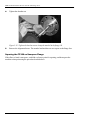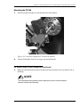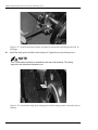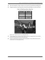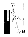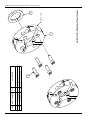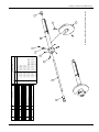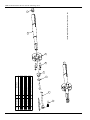
1
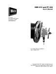
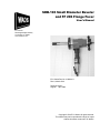
SDB-103 Small Diameter Beveler and FF 206 Flange Facer User’s Manual E.H. Wachs 600 Knightsbridge Parkway Lincolnshire, IL 60069 www.ehwachs.com E.H. Wachs Part No. 16-MAN-01 Rev. A, March 2014 Revision History: Original April 1996 Copyright © 2014 E.H. Wachs. All rights reserved. This manual may not be reproduced in whole or in part without the written consent of E.H. Wachs. SDB-103 Small Diameter Beveler and FF 206 Flange Facer Part No. 16-MAN-01, Rev. A E.H. Wachs Table of Contents Table of Contents Chapter 1: About This Manual . . . . . . . . . . . . . . . . . . . . . . . . . . . . . . . . . . . . . . . . . . . . . . . . . . . 1 Purpose of This Manual . . . . . . . . . . . . . . . . . . . . . . . . . . . . . . . . . . . . . . . . . . . . . . . . . . . . . . . . . . 1 How to Use The Manual. . . . . . . . . . . . . . . . . . . . . . . . . . . . . . . . . . . . . . . . . . . . . . . . . . . . . . . . . . 1 Symbols and Warnings . . . . . . . . . . . . . . . . . . . . . . . . . . . . . . . . . . . . . . . . . . . . . . . . . . . . . . . . . . . 2 Manual Updates and Revision Tracking. . . . . . . . . . . . . . . . . . . . . . . . . . . . . . . . . . . . . . . . . . . . . . 3 Chapter 2: Safety. . . . . . . . . . . . . . . . . . . . . . . . . . . . . . . . . . . . . . . . . . . . . . . . . . . . . . . . . . . . . . . 5 Operator Safety. . . . . . . . . . . . . . . . . . . . . . . . . . . . . . . . . . . . . . . . . . . . . . . . . . . . . . . . . . . . . . . . . 5 Safety Symbols. . . . . . . . . . . . . . . . . . . . . . . . . . . . . . . . . . . . . . . . . . . . . . . . . . . . . . . . . . . . . . 6 Protective Equipment Requirements. . . . . . . . . . . . . . . . . . . . . . . . . . . . . . . . . . . . . . . . . . . . . . 6 Safety Labels. . . . . . . . . . . . . . . . . . . . . . . . . . . . . . . . . . . . . . . . . . . . . . . . . . . . . . . . . . . . . . . . . . . 7 Chapter 3: Introduction to the Equipment. . . . . . . . . . . . . . . . . . . . . . . . . . . . . . . . . . . . . . . . . . 9 SDB 103 Small Diameter Beveler. . . . . . . . . . . . . . . . . . . . . . . . . . . . . . . . . . . . . . . . . . . . . . . . . . . 9 Optional Mandrels. . . . . . . . . . . . . . . . . . . . . . . . . . . . . . . . . . . . . . . . . . . . . . . . . . . . . . . . . . . 11 FF 206 Flange Facer. . . . . . . . . . . . . . . . . . . . . . . . . . . . . . . . . . . . . . . . . . . . . . . . . . . . . . . . . . . . 13 Performance Charts. . . . . . . . . . . . . . . . . . . . . . . . . . . . . . . . . . . . . . . . . . . . . . . . . . . . . . . . . . . . . 15 Specifications . . . . . . . . . . . . . . . . . . . . . . . . . . . . . . . . . . . . . . . . . . . . . . . . . . . . . . . . . . . . . . . . . 16 Operating Envelope. . . . . . . . . . . . . . . . . . . . . . . . . . . . . . . . . . . . . . . . . . . . . . . . . . . . . . . . . . . . . 16 Chapter 4: Assembly, Disassembly, and Storage . . . . . . . . . . . . . . . . . . . . . . . . . . . . . . . . . . . . 21 Storage Checklist . . . . . . . . . . . . . . . . . . . . . . . . . . . . . . . . . . . . . . . . . . . . . . . . . . . . . . . . . . . . . . 22 Chapter 5: Operating Instructions . . . . . . . . . . . . . . . . . . . . . . . . . . . . . . . . . . . . . . . . . . . . . . . 23 Pre-Operation Checklist . . . . . . . . . . . . . . . . . . . . . . . . . . . . . . . . . . . . . . . . . . . . . . . . . . . . . . . . . 23 Setting Up the SDB 103 . . . . . . . . . . . . . . . . . . . . . . . . . . . . . . . . . . . . . . . . . . . . . . . . . . . . . . . . . 24 Installing the Standard Mandrel . . . . . . . . . . . . . . . . . . . . . . . . . . . . . . . . . . . . . . . . . . . . . . . . 24 Installing the Extension Legs . . . . . . . . . . . . . . . . . . . . . . . . . . . . . . . . . . . . . . . . . . . . . . . . . . 26 Installing the Small I.D. Conversion Kit. . . . . . . . . . . . . . . . . . . . . . . . . . . . . . . . . . . . . . . . . . 27 Installing the Independent Fitting Mandrel. . . . . . . . . . . . . . . . . . . . . . . . . . . . . . . . . . . . . . . . 28 Mounting the SDB 103. . . . . . . . . . . . . . . . . . . . . . . . . . . . . . . . . . . . . . . . . . . . . . . . . . . . . . . . . . 31 Standard and Small I.D. Mandrels. . . . . . . . . . . . . . . . . . . . . . . . . . . . . . . . . . . . . . . . . . . . . . . 31 Independent Fitting Mandrel. . . . . . . . . . . . . . . . . . . . . . . . . . . . . . . . . . . . . . . . . . . . . . . . . . . 32 Installing and Centering on Elbows and Bends . . . . . . . . . . . . . . . . . . . . . . . . . . . . . . . . . 35 Installing Tooling . . . . . . . . . . . . . . . . . . . . . . . . . . . . . . . . . . . . . . . . . . . . . . . . . . . . . . . . . . . 36 Cutting the O.D. . . . . . . . . . . . . . . . . . . . . . . . . . . . . . . . . . . . . . . . . . . . . . . . . . . . . . . . . . . . . . . . 37 Cutting the I.D. . . . . . . . . . . . . . . . . . . . . . . . . . . . . . . . . . . . . . . . . . . . . . . . . . . . . . . . . . . . . . . . . 39 Tips for a Good Finish. . . . . . . . . . . . . . . . . . . . . . . . . . . . . . . . . . . . . . . . . . . . . . . . . . . . . . . . 40 FF 206 Flange Facing Setup . . . . . . . . . . . . . . . . . . . . . . . . . . . . . . . . . . . . . . . . . . . . . . . . . . . . . . 43 Removing the Mandrel. . . . . . . . . . . . . . . . . . . . . . . . . . . . . . . . . . . . . . . . . . . . . . . . . . . . . . . 43 Installing the Trip Collar . . . . . . . . . . . . . . . . . . . . . . . . . . . . . . . . . . . . . . . . . . . . . . . . . . . . . . 44 E.H. Wachs Part No. 16-MAN-01, Rev. Ai SDB-103 Small Diameter Beveler and FF 206 Flange Facer FF 206 Independent Fitting Mandrel Setup. . . . . . . . . . . . . . . . . . . . . . . . . . . . . . . . . . . . . . . . . . . 46 Squaring the FF 206 on Squared Flange . . . . . . . . . . . . . . . . . . . . . . . . . . . . . . . . . . . . . . . . . . 47 Squaring the FF 206 on Unsquare Flange. . . . . . . . . . . . . . . . . . . . . . . . . . . . . . . . . . . . . . . . . 48 Mounting the FF 206. . . . . . . . . . . . . . . . . . . . . . . . . . . . . . . . . . . . . . . . . . . . . . . . . . . . . . . . . 49 FF 206 Flange Facing Operating Procedure . . . . . . . . . . . . . . . . . . . . . . . . . . . . . . . . . . . . . . . . . . 49 Single-Point Beveling . . . . . . . . . . . . . . . . . . . . . . . . . . . . . . . . . . . . . . . . . . . . . . . . . . . . . . . . . . 53 Chapter 6: Routine Maintenance. . . . . . . . . . . . . . . . . . . . . . . . . . . . . . . . . . . . . . . . . . . . . . . . . 57 Break-In Period. . . . . . . . . . . . . . . . . . . . . . . . . . . . . . . . . . . . . . . . . . . . . . . . . . . . . . . . . . . . . . . . 57 Periodic Inspection Checklist. . . . . . . . . . . . . . . . . . . . . . . . . . . . . . . . . . . . . . . . . . . . . . . . . . . . . 58 Lubrication. . . . . . . . . . . . . . . . . . . . . . . . . . . . . . . . . . . . . . . . . . . . . . . . . . . . . . . . . . . . . . . . . . . 59 Chapter 7: Service and Repair. . . . . . . . . . . . . . . . . . . . . . . . . . . . . . . . . . . . . . . . . . . . . . . . . . . 61 SDB 103 Service. . . . . . . . . . . . . . . . . . . . . . . . . . . . . . . . . . . . . . . . . . . . . . . . . . . . . . . . . . . . . . . 61 Replacing the Front Bushing. . . . . . . . . . . . . . . . . . . . . . . . . . . . . . . . . . . . . . . . . . . . . . . . . . . 61 FF 206 Service . . . . . . . . . . . . . . . . . . . . . . . . . . . . . . . . . . . . . . . . . . . . . . . . . . . . . . . . . . . . . . . . 62 Castle Nut Adjustment . . . . . . . . . . . . . . . . . . . . . . . . . . . . . . . . . . . . . . . . . . . . . . . . . . . . . . . 62 Replacing the Feed Screw or Male Tool Slide. . . . . . . . . . . . . . . . . . . . . . . . . . . . . . . . . . . . . . 62 Feed Tension Adjustment . . . . . . . . . . . . . . . . . . . . . . . . . . . . . . . . . . . . . . . . . . . . . . . . . . . . . 63 Chapter 8: Parts Lists and Drawings. . . . . . . . . . . . . . . . . . . . . . . . . . . . . . . . . . . . . . . . . . . . . . 65 Chapter 9: Accessories and Spare Parts . . . . . . . . . . . . . . . . . . . . . . . . . . . . . . . . . . . . . . . . . . . 81 Accessories. . . . . . . . . . . . . . . . . . . . . . . . . . . . . . . . . . . . . . . . . . . . . . . . . . . . . . . . . . . . . . . . . . . 81 Tooling . . . . . . . . . . . . . . . . . . . . . . . . . . . . . . . . . . . . . . . . . . . . . . . . . . . . . . . . . . . . . . . . . . . . . . 82 Chapter 10: Ordering Information. . . . . . . . . . . . . . . . . . . . . . . . . . . . . . . . . . . . . . . . . . . . . . . 85 Ordering Replacement Parts. . . . . . . . . . . . . . . . . . . . . . . . . . . . . . . . . . . . . . . . . . . . . . . . . . . . . . 85 Repair Information . . . . . . . . . . . . . . . . . . . . . . . . . . . . . . . . . . . . . . . . . . . . . . . . . . . . . . . . . . . . . 85 Warranty Information. . . . . . . . . . . . . . . . . . . . . . . . . . . . . . . . . . . . . . . . . . . . . . . . . . . . . . . . . . . 86 Return Goods Address. . . . . . . . . . . . . . . . . . . . . . . . . . . . . . . . . . . . . . . . . . . . . . . . . . . . . . . . . . . 86 ii Part No. 16-MAN-01, Rev. A E.H. Wachs Chapter 1, About This Manual Chapter 1 About This Manual Purpose of This Manual This manual explains how to operate and maintain the SDB-103 small diameter beveler (SDB) and FF 206 flange facer. It includes instructions for set-up, operation, and maintenance. It also contains parts lists, diagrams, and service information to help you order replacement parts and perform user-serviceable repairs. Before operating the machine, read through this manual and become familiar with all instructions. How to Use The Manual This manual is organized to help you quickly find the information you need. Each chapter describes a specific topic on using or maintaining your equipment. Use these instructions to operate and maintain the equipment. E.H. Wachs Part No. 16-MAN-01, Rev. A1 SDB-103 Small Diameter Beveler and FF 206 Flange Facer Symbols and Warnings The following symbols are used throughout this manual to indicate special notes and warnings. They appear in the outside column of the page, next to the section they refer to. Make sure you understand what each symbol means, and follow all instructions for cautions and warnings. This is the safety alert symbol. It is used to alert you to potential personal injury hazards. Obey all safety messages that follow this symbol to avoid possible injury or death. WARNING A WARNING alert with the safety alert symbol indicates a potentially hazardous situation that could result in serious injury or death. CAUTION A CAUTION alert with the safety alert symbol indicates a potentially hazardous situation that could result in minor or moderate injury. A CAUTION alert with the damage alert symbol indicates a situation that will result in damage to the equipment. This is the equipment damage alert symbol. It is used to alert you to potential equipment damage situations. Obey all messages that follow this symbol to avoid damaging the equipment or workpiece on which it is operating. IMPORTANT An IMPORTANT alert with the damage alert symbol indicates a situation that may result in damage to the equipment. NOTE This symbol indicates a user note. Notes provide additional information to supplement the instructions, or tips for easier operation. 2 Part No. 16-MAN-01, Rev. A E.H. Wachs Chapter 1, About This Manual: Manual Updates and Revision Tracking Manual Updates and Revision Tracking Occasionally, we will update manuals with improved operation or maintenance procedures, or with corrections if necessary. When a manual is revised, we will update the revision history on the title page. Current versions of E.H. Wachs Company manuals are also available in PDF format. You can request an electronic copy of this manual by emailing customer service at [email protected]. You may have factory service or upgrades performed on the equipment. If this service changes any technical data or operation and maintenance procedures, we will include a revised manual when we return the equipment to you. E.H. Wachs Part No. 16-MAN-01, Rev. A3 EU Declaration OF CONFORMITY WITH COUNCIL DIRECTIVE 98/37/EC Issue Details: DATE: 4/13/2015 Directives: Machinery Safety Directive 98/37/EC Conforming Machinery: Pipe Beveling & Cut-Off Machines: Manufacturer: E.H. Wachs Company 600 Knightsbridge Parkway Lincolnshire IL 60069 USA Patrick Fuss Director of International Sales and Service Wachs Limited 3 Millbuck Way Springvale Industrial Estate Sandbach, Chesire CW11 3JA United Kingdom BS EN 292-1:1991, BS EN 292-2: 1991, BS EN 294:1992, BS EN 349:1998, BS EN 418:1992, BS EN 60204-1:1998 BS EN 982:1996, BS EN 983:1996 Responsible Representative: Harmonised Standards & Other Technical Standards/Specifications Applied or Referenced: Provisions with which Conformity is Declared: Place: E.H.Wachs, Lincolnshire, IL USA Model#: 16, 56, 66, 70, 71, 72-000-XX Serial #: Essential Health and Safety Requirements of Annex 1 of the Machinery Directive We hereby certify that the machinery described above conforms with the essential health and safety requirements of Council Directive 98/37/EC on the approximation of the laws of the Member States relating to the safety of machinery. Signed: Signatory: Pete Mullally Quality Manager E.H. Wachs Company Chapter 2, Safety Chapter 2 Safety E.H. Wachs takes great pride in designing and manufacturing safe, high-quality products. We make user safety a top priority in the design of all our products. Read this chapter carefully before operating the SDB 103/FF 206. It contains important safety instructions and recommendations. Operator Safety Follow these guidelines for safe operation of all E.H. Wachs equipment. Look for this symbol throughout the manual. It indicates a personal injury hazard. • READ THE OPERATING MANUAL. Make sure you understand all setup and operating instructions before you begin. Keep this manual with the machine. • INSPECT MACHINE AND ACCESSORIES BEFORE USE. Before starting the machine, look for loose bolts or nuts, leaking lubricant, rusted components, and any other physical conditions that may affect operation. Properly maintaining the machine can greatly decrease the chances for injury. • ALWAYS READ PLACARDS AND LABELS. Make sure all labels, placards and stickers are in place, clearly legible, and in good condition. Refer to “Safety Labels” later in this chapter for label locations on the machine. Replace any damaged or missing safety labels; see the ordering information at the end of this manual. • KEEP CLEAR OF MOVING PARTS. Keep hands, arms, and fingers clear of all rotating or moving parts. Always turn the machine off and disconnect the power source before doing any adjustments or service. E.H. Wachs Part No. 16-MAN-01, Rev. A5 SDB-103 Small Diameter Beveler and FF 206 Flange Facer • SECURE LOOSE CLOTHING AND JEWELRY. Secure or remove loose-fitting clothing and jewelry, and securely bind long hair, to prevent them from getting caught in moving parts of the machine. • KEEP WORK AREA CLEAR. Keep all clutter and nonessential materials out of the work area. Only people directly involved with the work being performed should have access to the area. Safety Symbols This icon is displayed with any safety alert that indicates a personal injury hazard. WARNING This safety alert indicates a potentially hazardous situation that, if not avoided, could result in death or serious injury. CAUTION This safety alert, with the personal injury hazard symbol, indicates a potentially hazardous situation that, if not avoided, could result in minor or moderate injury. Protective Equipment Requirements For additional information on eye and face protection, refer to Federal OSHA regulations, 29 Code of Federal Regulations, Section 1910.133., Eye and Face Protection and American National Standards Institute, ANSI Z87.1, Occupational and Educational Eye and Face Protection. Z87.1 is available from the American National Standards Institute, Inc., 1430 Broadway, New York, NY 10018. WARNING Always wear impact resistant eye protection while operating or working near this equipment. Hearing protectors are required in high noise areas, 85 dBA or greater. The operation of other tools and equipment in the area, reflective surfaces, process noises, and resonant structures can increase the noise level in the area. For additional information on hearing protection, refer to Federal OSHA regulations, 29 Code of Federal Regulations, Section 1910.95, Occupational Noise Exposure and ANSI S12.6 Hearing Protectors. 6 Part No. 16-MAN-01, Rev. A E.H. Wachs Chapter 2, Safety: Safety Labels CAUTION Personal hearing protection is recommended when operating or working near this tool. Safety Labels The following safety labels are on the SDB 103. If the stickers are damaged or missing, replace them immediately. See Chapter 10 for ordering information. Figure 2-1. The Caution sticker is on the SDB 103 air motor. Wear ear and eye protection while operating the machine. (Part number 90-401-03.) Figure 2-2. The Warning sticker is on the SDB 103. Do not put your hands near the rotating head while the machine is running. (Part number 66-147-00.) E.H. Wachs Part No. 16-MAN-01, Rev. A7 SDB-103 Small Diameter Beveler and FF 206 Flange Facer 8 Part No. 16-MAN-01, Rev. A E.H. Wachs Chapter 3, Introduction to the Equipment Chapter 3 Introduction to the Equipment SDB 103 Small Diameter Beveler The SDB 103 is a portable pipe prepping machine that can face, bevel, compound bevel, J-prep, and counterbore open ended pipe and tubing. The handheld SDB 103 mounts on the pipe inside diameter (I.D.) using a self-centering mandrel clamp system. It will prep open-ended pipe and tubing from 1.16” to 4.18” I.D. (29.5-106.2 mm), and up to 4.5” (114.3 mm) outside diameter (O.D.). The SDB 103 can be easily installed by one operator in just a few minutes. Different sized clamp leg sets are provided to cover the full range of operation. Select and install the appropriate leg set for the pipe you are machining, install the tooling, and mount the machine on the pipe using the simple drawbar mechanism. An air or electric motor drives the rotating tool head. The operator feeds the tooling into the pipe face using a manual feed handle. A calibrated feed dial allows precise material removal. The tool head has three tools slots, allowing multiple facing, beveling, and counterboring operations to be performed simultaneously. The machine includes all accessories and tools necessary for operation, and is shipped in a durable, waterproof storage case. E.H. Wachs Part No. 16-MAN-01, Rev. A9 SDB-103 Small Diameter Beveler and FF 206 Flange Facer Clamp leg sets Mandrel Tool head Machine body Feed handle Air motor Drawbar Figure 3-1. The photo shows the SDB 103 components and accessories. 16-021-07 16-021-01 16-021-06 16-021-02 16-021-03 16-021-05 16-021-04 Figure 3-2. The standard clamp leg sets (identified by part number) fit the standard mandrel to a range of pipe and tube sizes. See the tables in Chapter 5 for the clamping range for each leg set. 10 Part No. 16-MAN-01, Rev. A E.H. Wachs Chapter 3, Introduction to the Equipment: SDB 103 Small Diameter Beveler Facing tool 26-410-02 10° Deburring tool 26-412-02 37.5° Beveling tool 26-411-01 Counterbore/ facing tool 26-426-00 Figure 3-3. The SDB standard tooling allows the operator to face, bevel, J-prep, and counterbore pipe and tube. Optional Mandrels A small-diameter conversion kit (16-401-00) with a smaller mandrel and tool head is available. The conversion kit allows you to install the machine on pipe I.D.s from 0.875” to 1.75” (22.231.8 mm). NOTE Collet-style mandrels are also available for pipe or tube. Call E.H. Wachs customer service to discuss your application’s requirements. The standard and small I.D. mandrels automatically center the machine on the I.D. and squares it to the centerline of the pipe. If you need to mount the machine in a pipe that is on a bend or that has limited I.D. access, an independent fitting mandrel (16-414-00) with dowel-style clamp legs is available as an option. With the independent fitting mandrel, you can adjust the machine to be squared to the pipe end surface, rather than the centerline. (This mandrel can also be used to mount the FF 206.) A squaring plate for aligning the machine during installation is provided with the mandrel. E.H. Wachs Part No. 16-MAN-01, Rev. A11 SDB-103 Small Diameter Beveler and FF 206 Flange Facer Figure 3-4. The independent fitting mandrel shown in the photo uses dowel-style clamp legs, shown at right. Figure 3-5. The squaring plate is used to square the SDB to the pipe face when using the independent fitting mandrel. It is also used for mounting the FF 206. 12 Part No. 16-MAN-01, Rev. A E.H. Wachs Chapter 3, Introduction to the Equipment: FF 206 Flange Facer FF 206 Flange Facer NOTE The standard FF 206 system does not contain all components necessary to use it as an SDB 103. A conversion kit (16-420-00) is available to convert the FF 206 to the SDB 103. With the FF 206 conversion kit, the SDB 103 can be quickly converted to a flange facing machine. The FF 206 will finish raised and flat flange faces from 2.0” (50.8 mm) I.D. up to 6.0” (152 mm) O.D. The FF 206 can be purchased as a fully integrated machine, or as a kit to upgrade the SDB 103. SDB 103 with independent fitting mandrel and leg sets Radial tool slide Tool holder Trip ring Squaring plate Figure 3-6. The photo shows the components of the FF 206, including the SDB 103 machine. The FF 206 uses a radial-feed tool slide to advance the cutting tool across the flange face. A starwheel on the slide is advanced by striking mechanical trips as the machine rotates. The starwheel turns a feed screw that drives the slide in the feed direction. Various finishes can be cut with the FF 206 by varying the number of engaged trips on the trip ring. Finish options include flange face, record groove, or RMS 63 finish. E.H. Wachs Part No. 16-MAN-01, Rev. A13 SDB-103 Small Diameter Beveler and FF 206 Flange Facer Tool holder Feed screw Starwheel Feed direction SDB head mounting interface Figure 3-7. The flange facing slide mounts on the SDB 103 to face flanges. Figure 3-8. The single-point tool holder with tool inserts is used for flange facing. 14 Part No. 16-MAN-01, Rev. A E.H. Wachs Chapter 3, Introduction to the Equipment: Performance Charts Performance Charts The following table is the result of extensive testing. Tests were performed on carbon steel and stainless steel, as well as exotic materials such as HK40 and incalloys. Table 1: SDB Application and Performance Nominal Pipe Size ASA Pipe Schedule Carbon and Stainless Steel 5 (b) 10 (b) 40 60 80 120 160 3/4”(a) 1”(a) 1 1/4” 1 1/2” 2” 2 1/2” 3” 3 1/2” 4” (c) = Effective prepping range (a) = Limited by mandrel I.D. (b) = Small I.D. conversion kit required (c) = Carbon steel only Table 2: FF 206 Flange Surface Trip Chart E.H. Wachs Trips Engaged RMS Finish 1 63 RMS 2 125 RMS 4 250 RMS 6 500 RMS Part No. 16-MAN-01, Rev. A15 SDB-103 Small Diameter Beveler and FF 206 Flange Facer Specifications Machine capacity SDB 103: Pipe and tube 0.875” (22.2 mm) I.D. to 4.5” (114 mm) O.D. FF 206: Flange O.D. from 2.0” (51 mm) to 6.0” (152 mm). Machining functions (SDB 103) Facing, O.D. beveling, compound beveling, J prepping, and I.D. counterboring of openend pipe and tube. Use up to four tools simultaneously. Machining functions (FF 206) Single-point finishing of flat and raised flange faces. Surface finishes include 500 RMS (record groove), 250 RMS, 125 RMS, and 63 RMS. Mounting mechanism I.D.-mounted mandrel with adjustable clamping legs and multiple legs sets to cover full I.D. range. Standard diameter, small I.D., and independent fitting (short clearance) mandrels available. Drive motors Air motor, 110 V or 220 V electric motor Air requirements 16-000-01: 35 cfm (991 l/min) Electrical requirements 16-000-02: 110 VAC, 50-60 Hz, 8.0 A 16-000-03: 220 VAC 50-60 Hz, 4.6 A Controls Manual clamping, manual axial feed, variable speed control (air or electric). FF 206: mechanical radial feed using starwheel/trip mechanism. Feed features 2.5” (63.5 mm) maximum axial feed; 0.0625” (1.59 mm) feed per handle revolution. Indexed feed dial for precise depth. Tooling Standard Wachs form tools for facing, beveling, and counterboring. Single-point holder with inserts for FF 206 flange facing. High speed steel or carbide. Custom tooling available. Dimensions and weights See operating envelope drawings in next section. Operating Envelope The following drawings illustrate the overall dimensions and operating envelopes for the SDB 103 with air and electric motors, and for the FF 206. 16 Part No. 16-MAN-01, Rev. A E.H. Wachs E.H. Wachs NOTE: SEE 16-409-00 FOR EXTENSION LEG CLAMPING RANGES 1.57 MAX 39.9 1.16 MIN 29.6 DETAIL-A LEGS SHOWN FULLY EXTENDED LEGS SHOWN FULLY RETRACTED 4.75 120.7 DIMENSIONS IN BRACKETS ARE MILLIMETERS 2.46 62.5 1.28 32.6 6.26 159.0 SDB 103 Operating Envelope 1.28 REF 32.6 LEGS SHOWN FULLY RETRACTED SEE DETAIL-A 3.36 MAX 85.3 TRAVEL 5.29 134.5 26-410-02 FACING TOOL .75 19.1 16.75 MAX 425.5 3.25 REF 82.5 12.33 313.1 3.19 81.0 Chapter 3, Introduction to the Equipment: Operating Envelope Part No. 16-MAN-01, Rev. A17 18 Part No. 16-MAN-01, Rev. A NOTE: SEE 16-409-00 FOR EXTENSION LEG CLAMPING RANGES 1.57 MAX 39.9 1.16 MIN 29.6 4.75 120.7 DETAIL-A LEGS SHOWN FULLY EXTENDED LEGS SHOWN FULLY RETRACTED DIMENSIONS IN BRACKETS ARE MILLIMETERS 2.46 62.5 1.28 32.6 6.26 159.0 3.36 MAX 85.3 TRAVEL 5.29 134.5 16-000-02 and 16-000-03 SDB 103 Operating Envelope 1.28 REF 32.6 LEGS SHOWN FULLY RETRACTED SEE DETAIL-A 26-410-02 FACING TOOL .75 19.1 16.75 MAX 425.5 19.24 REF 488.7 10.07 REF 255.7 6.69 169.8 3.19 81.0 SDB-103 Small Diameter Beveler and FF 206 Flange Facer E.H. Wachs E.H. Wachs .97 MIN 24.7 .87 MIN 22.1 DIMENSIONS IN BRACKETS ARE MILLIMETERS 1.25MAX 31.7 1.11 MAX 28.3 CLAMPING RANGE 3.13 REF 79.4 2.70 MAX 68.6 TRAVEL SDB 103 Operating Envelope Small I.D. Conversion Kit, 16-401-00 LEGS (16-068-00) SHOWN FULLY RETRACTED AND WITHOUT O-RING (16-070-02) LEGS (16-067-00) SHOWN FULLY RETRACTED AND WITHOUT O-RING (16-070-01) 2.43 MAX 61.7 TRAVEL Chapter 3, Introduction to the Equipment: Operating Envelope Part No. 16-MAN-01, Rev. A19 R6.63 168.3 SWING 20 Part No. 16-MAN-01, Rev. A 6.19 157.1 FF 206 Operating Envelope 1.77 REF 45.0 DIMENSIONS IN BRACKETS ARE MILLIMETERS 16-042-00 TOOL HOLDER 60-702-00 INSERT TOOL .38 9.5 4.23 MAX 107.3 TRAVEL 3.14 79.9 .33 8.3 14.07 357.3 6.26 159.0 3.25 REF 82.5 12.33 313.1 .25 6.4 THREAD ENGAGEMENT ON MANDREL 3.19 81.0 SDB-103 Small Diameter Beveler and FF 206 Flange Facer E.H. Wachs Chapter 4, Assembly, Disassembly, and Storage Chapter 4 Assembly, Disassembly, and Storage The SDB 103 comes fully assembled and ready to operate. See the instructions in Chapter 5 for configuring clamp legs, mandrels, and tool heads for various applications. Instructions are also provided for converting the SDB 103 to the FF 206 flange facer. The SDB 103 and FF 206 are shipped in custom-configured storage cases. Keep the machines in their cases when not in use. Figure 4-1 and Figure 4-2 show the machines in their cases. SDB 103 Clamp leg sets Hand tools Figure 4-1. The photo shows the SDB 103 in its case. E.H. Wachs Part No. 16-MAN-01, Rev. A21 SDB-103 Small Diameter Beveler and FF 206 Flange Facer FF 206 trip ring Squaring plate Hand tools Tool holder and inserts FF 206 slide SDB 103 machine with independent fitting mandrel Clamp leg sets Figure 4-2. The photo shows the components of the FF 206, including the SDB 103 machine, in its storage case. Storage Checklist Before storing the SDB 103 or FF 206, perform the following maintenance steps: • Put oil in the air motor oiler, and operate the motor for a few seconds to lubricate its internal components. • Apply grease to the grease fitting on the SDB machine body. • Rub a coating of light oil on the drawbar and mandrel. • Rub a coating of oil on the feed screw of the FF 206 slide. • Oil the dovetail surfaces on the FF 206 slide. • If you will be storing the machine longer than 30 days, put desiccant packets in the case to prevent corrosion. 22 Part No. 16-MAN-01, Rev. A E.H. Wachs Chapter 5, Operating Instructions Chapter 5 Operating Instructions Pre-Operation Checklist To avoid damaging the equipment, follow these usage guidelines. 1. Inspect the bore of the rotating head for dirt and metal chips. Clean the bore with compressed air or solvent as necessary. 2. Wipe the mandrel clean, and apply a light coating of oil. Figure 5-1. When cleaning the mandrel, inspect the threads for damage. 3. Lubricate the machine according to the guidelines in Chapter 6. E.H. Wachs Part No. 16-MAN-01, Rev. A23 SDB-103 Small Diameter Beveler and FF 206 Flange Facer Setting Up the SDB 103 Installing the Standard Mandrel NOTE You do not normally need to remove the mandrel from the machine. Use this procedure if the mandrel has been removed for service or re-configuring the SDB 103. These instructions are for installing the standard mandrel on the SDB 103. For instructions on the optional mandrels, see “Installing the Small I.D. Conversion Kit” and “Installing the Independent Fitting Mandrel” later in this section. 1. Insert the threaded end of the mandrel through the front of the rotating head. Be careful not to damage the head bushing. Figure 5-2. If it is not already installed, insert the mandrel through the tool head as shown. 2. Align the keyway slots of the mandrel with the internal keys of the beveling head. 3. Insert the mandrel until it stops. Rotate the feed handle clockwise to engage the threads into the feed nut, and continue feeding until the mandrel shaft is approximately ¾” (19 mm) beyond the end cap. 24 Part No. 16-MAN-01, Rev. A E.H. Wachs Chapter 5, Operating Instructions: Setting Up the SDB 103 Figure 5-3. Turn the feed handle to thread the mandrel into the machine body NOTE The drawbar nut and the collar nut must be removed to remove the mandrel from the machine body. 4. Install the draw bar nut, and then install and tighten the collar nut. The collar nut captivates the draw bar nut so the draw bar nut can be turned to expand and contract the mandrel legs. Figure 5-4. Tighten the collar nut with finger pressure to captivate the draw bar nut on the mandrel. E.H. Wachs Part No. 16-MAN-01, Rev. A25 SDB-103 Small Diameter Beveler and FF 206 Flange Facer Installing the Extension Legs Install the appropriate leg set to fit the pipe you are machining. Table 1 gives the I.D. range for each leg set provided with the SDB 103 standard mandrel. Table 1: Standard Mandrel Extension Legs 1. Leg Set Thickness I.D. Range None N/A 1.16–1.57” (37.8–39.8 mm) 16-021-01 0.218” (5.5 mm) 1.53–1.94” (38.8–49.25 mm) 16-021-02 0.405” (10.2 mm) 1.90–2.32” (48.2–58.9 mm) 16-021-03 0.592” (15.0 mm) 2.27–2.69” (57.6–68.7 mm) 16-021-04 0.780” (19.8 mm) 2.64–3.06” (67.0–77.7 mm) 16-021-05 0.968” (24.5 mm) 3.02–3.43” (76.7–87.1 mm) 16-021-06 1.155” (29.3 mm) 3.39–3.81” (86.1–96.7 mm) 16-021-07 1.343” (34.1 mm) 3.76–4.18” (95.5–106.1 mm) To determine which leg set is required, measure the work piece pipe I.D. and refer to the extension leg chart in Table 1. Figure 5-5. Use a scale to measure the I.D. of the pipe. 26 Part No. 16-MAN-01, Rev. A E.H. Wachs Chapter 5, Operating Instructions: Setting Up the SDB 103 Figure 5-6. Each leg set is stamped with a reference number which corresponds to the pipe I.D. range the leg set will accommodate. 2. Select the required extension leg set. The extension legs each have two captivated screws used to fasten them to the mandrel legs. 3. Tighten the captivated screws on the extension legs to attach the extension legs to the mandrel legs. Figure 5-7. Attach the clamp legs to the mandrel and tighten the 2 screws in each leg. Installing the Small I.D. Conversion Kit The small I.D. conversion kit (part number 16-401-00) allows you to install the SDB 103 on pipe I.D.s down to 0.875” (22.2 mm). The kit includes a thinner mandrel and a tool head with a smaller bore. Use the following procedure to replace the standard mandrel and tool head. 1. Loosen and remove the collar nut and drawbar nut on the standard mandrel. 2. Turn the feed handle counter-clockwise until you can remove the standard mandrel through the tool head of the SDB 103. E.H. Wachs Part No. 16-MAN-01, Rev. A27 SDB-103 Small Diameter Beveler and FF 206 Flange Facer 3. Remove the standard tool head from the SDB 103 by taking out the 4 screws holding it. 4. Remove the clamp legs on the small I.D. mandrel. 5. Remove the drawbar nut and drawbar from the small I.D. mandrel. 6. Insert the small I.D. mandrel into the machine body. Position the mandrel so that the keyways are aligned with the keys in the machine, and turn the feed handle clockwise to thread the mandrel into the feed nut. 7. Slide the small I.D. rotating head over the end of the mandrel. Install it on the machine body with the 4 screws. 8. Measure the pipe I.D. and select the appropriate leg set and o-ring to fit. Make sure to use the correct o-ring for the leg set you are using. Refer to Table 2 below. 9. Install the legs onto the drawbar chuck, using the o-ring to hold them in place. 10. Insert the small I.D. drawbar through the mandrel and re-install the drawbar nut. NOTE When returning legs to their proper position in the mandrel assembly, the O ring that secures them must be in the correct position prior to reinstalling the draw bar assembly. The O ring will not slip over the end of the draw bar once it has been installed. Table 2: Small-Diameter Mandrel Extension Legs Leg Set I.D. Range O-Ring 16-067-00 0.875–1.125” (22.2–28.6 mm) 16-070-01 16-068-00 1.00–1.250” (25.4–31.8 mm) 16-070-02 Installing the Independent Fitting Mandrel If the pipe you are machining has an obstruction or bend that does not allow enough room for the standard mandrel to mount, use the independent fitting mandrel instead. Follow this procedure to install the independent fitting mandrel. The independent fitting mandrel is not self-squaring. You will need to use the squaring plate provided with it to square the machine to the pipe face. 1. If necessary, remove the standard mandrel from the SDB 103. 2. Insert the independent fitting mandrel through the tool head until it stops. Position the mandrel so that the keyways are aligned with the keys in the machine, and turn the feed handle clockwise to thread the mandrel into the feed nut. 3. Measure the pipe I.D., and select the extension leg set required. Refer to the extension leg chart in Table 3 below. 28 Part No. 16-MAN-01, Rev. A E.H. Wachs Chapter 5, Operating Instructions: Setting Up the SDB 103 Table 3: Independent Fitting Mandrel Extension Legs 4. Part Number (Solid/adjustable) Length (Solid/Adjustable) Min. Diameter Max. Diameter 16-053-01 N/A 0.0794” (20.1 mm) N/A 1.95” (49.5 mm) 2.31” (58.6 mm) 16-053-02/ 16-054-02 0.944” (23.9 mm) 0.824” (20.9 mm) 2.25” (57.1 mm) 2.61” (66.2 mm) 16-053-03/ 16-054-03 1.094” (27.7 mm) 0.974” (24.7 mm) 2.55” (64.7 mm 2.91” (73.9 mm) 16-053-04/ 16-054-04 1.244” (31.5 mm) 1.124” (28.5 mm) 2.85” (72.3 mm) 3.21” (81.5 mm) 16-053-05/ 16-054-05 1.394” (35.4 mm) 1.274” (32.3 mm) 3.15” (80.0 mm) 3.51” (89.1 mm) 16-053-06/ 16-054-06 1.544” (39.2 mm) 1.424” (66.1 mm) 3.45” (87.6 mm) 3.81” (96.7 mm) 16-053-07/ 16-054-07 1.694” (43.0 mm) 1.574” (39.9 mm) 3.75” (95.2 mm) 4.11” (104.3 mm) Insert the legs into the mandrel head. The adjustment screw in the adjustable leg must be completely screwed in. Figure 5-8. Attach the leg adjustment screw to the adjustable leg and screw it in fully. E.H. Wachs Part No. 16-MAN-01, Rev. A29 SDB-103 Small Diameter Beveler and FF 206 Flange Facer Figure 5-9. Insert the legs into the independent fitting mandrel. 30 Part No. 16-MAN-01, Rev. A E.H. Wachs Chapter 5, Operating Instructions: Mounting the SDB 103 Mounting the SDB 103 Standard and Small I.D. Mandrels 1. Insert the mandrel chuck into the pipe. For best results, keep the end of the chuck legs close to the pipe edge. NOTE The maximum depth of penetration into the pipe should be ¾” (19 mm) from the rear of the mandrel legs to the pipe edge. This will allow for a normal prep and still keep the machine body and rotating head stable. Figure 5-10. Insert the mandrel into the pipe. 2. Hold the machine with the mandrel at the desired clamping location. NOTE Torque the drawbar nut to 25 lb-ft. 3. Rotate the draw bar nut with the supplied wrench to expand the mandrel legs into the I.D. of the pipe. The chuck legs will automatically center the machine to the pipe. E.H. Wachs Part No. 16-MAN-01, Rev. A31 SDB-103 Small Diameter Beveler and FF 206 Flange Facer Figure 5-11. Hold the machine in place and tighten the drawbar nut. Independent Fitting Mandrel 1. Set the mandrel assembly, with the required leg set installed, into the pipe. NOTE You can install the independent fitting mandrel in the pipe before putting it on the SDB 103 or FF 206 machine. The mandrel may be easier to square without the SDB 103 attached. 32 Part No. 16-MAN-01, Rev. A E.H. Wachs Chapter 5, Operating Instructions: Mounting the SDB 103 Figure 5-12. Insert the mandrel into the pipe. 2. Put the squaring plate over the shaft of the mandrel and slide it against the head. Pull the mandrel back in the pipe if necessary. Figure 5-13. Put the squaring plate onto the mandrel. E.H. Wachs Part No. 16-MAN-01, Rev. A33 SDB-103 Small Diameter Beveler and FF 206 Flange Facer 3. Tighten the set screws in the squaring plate to secure it to the mandrel. Figure 5-14. Tighten both set screws in the squaring plate to secure and center it to the mandrel. 4. Push the mandrel into the pipe so that the squaring plate is pressed tight against the pipe face. Tighten the drawbar nut while holding the mandrel in this position. 5. Loosen the set screws in the squaring plate and remove the plate from the mandrel. Check the location of the legs in the pipe. Figure 5-15. The mandrel legs should be close to the edge of the pipe. 6. 34 If you need to install the SDB 103 or FF 206 on the mandrel, slide the tool head over the mandrel and position the machine to line up the keys and the keyway slots. Turn the feed handle clockwise to thread the mandrel into the machine. Part No. 16-MAN-01, Rev. A E.H. Wachs Chapter 5, Operating Instructions: Mounting the SDB 103 Installing and Centering on Elbows and Bends 1. When inserting the mandrel into the pipe, position the adjustable leg at the “short radius bend” side of the pipe. Make sure the screw on the adjustable leg is screwed all the way in. Measurement “B” ADJUSTABLE LEG Measurement “A” Short radius bend Figure 5-16. Install the mandrel with the adjustable leg positioned at the short radius bend of the pipe. 2. Using the squaring plate as described in the previous section, snug the drawbar nut to hold the mandrel in place. Remove the squaring plate. NOTE If the end of the pipe is not square, you will have to establish a reference point for squaring. 3. Measure the distance over the adjustable leg from the pipe I.D. to the mandrel shaft. Write this number down as measurement “A”. 4. At the position 180° across from the adjustable leg, measure the distance from the pipe I.D. to the mandrel shaft. Write this number down as measurement “B”. • If the two measurements are close enough for the tolerance of your application, you do not need to adjust the centering. • If you need to re-center the mandrel, you will have to remove the it and adjust the screw in the adjustable leg. • Subtract measurement “A” from measurement “B” and divide the result by 2. This is the required adjustment distance; write it down as “C”. B – A = C 2 • One turn of the adjustment screw extends the screw by 0.035" (0.89 mm). Divide “C” by this amount to determine how many turns to adjust the screw. E.H. Wachs Part No. 16-MAN-01, Rev. A35 SDB-103 Small Diameter Beveler and FF 206 Flange Facer Turns = C 0.035" 5. Before removing the mandrel, attach the squaring plate to it with the plate firmly against the pipe face. Loosen the drawbar nut to remove the mandrel. 6. Turn the adjustment screw the number of turns you calculated above. NOTE This procedure assumes that the pipe radius is greater at the “short radius bend” side of the pipe (measurement “A”). If the radius is greater on the other side (measurement “B”), adjust the leg as described, but re-install the mandrel with the adjustable leg in the opposite direction. 7. With the squaring plate still on the mandrel, re-install the mandrel on the pipe and tighten the drawbar nut. 8. Remove the squaring plate and repeat the “A” and “B” measurements. If necessary, re-adjust the centering using the same procedure. Installing Tooling Refer to the tool selection chart to select the appropriate tooling. 1. Loosen the tool bit wedge screw. 2. Install the facing tool in the rotating head slot. Direction of rotation Align tool with pipe face Figure 5-17. Position the tooling so the tool bit completely contacts the pipe face. 3. Install the beveling tool in the rotating head slot. 4. All tool bits must be installed so the cutting edge is facing clockwise as seen from the manual feed handle. 36 Part No. 16-MAN-01, Rev. A E.H. Wachs Chapter 5, Operating Instructions: Cutting the O.D. Figure 5-18. Direction of rotation is indicated by the arrow. 5. Tighten the tool bit wedge screws to secure the tools in place. Cutting the O.D. 1. Connect the drive motor to the motor adapter. Tighten the screws holding the motor in place. IMPORTANT An air treatment module (ATM) with an inline air oiler / moisture separator is required for proper lubrication and operation of the SDB air motor. Machine life can be shortened and the warranty can be voided if an ATM is not used. An ATM can be purchased from E.H. Wachs or a third party. 2. Connect power (air or electric) to the drive motor. 3. Start the machine, and turn the manual feed handle clockwise until the cutting tools contact the pipe. E.H. Wachs Part No. 16-MAN-01, Rev. A37 SDB-103 Small Diameter Beveler and FF 206 Flange Facer Figure 5-19. To face the pipe, turn the feed handle clockwise. 4. Continue operating the machine until the pipe has a clean finish. 5. When the desired finish is complete, turn the feed handle counter-clockwise to retract the tool away from the pipe face. Turn off the drive motor. 6. Retract the tool head fully by turning the manual feed handle counter-clockwise. Figure 5-20. Retract the tooling after the operation is complete by turning the feed handle counter-clockwise. 7. 38 Disconnect the power source from the drive motor. Part No. 16-MAN-01, Rev. A E.H. Wachs Chapter 5, Operating Instructions: Cutting the I.D. Cutting the I.D. 1. Loosen the tool bit wedge screw, and remove the facing tool. 2. Insert the counterbore tool. Figure 5-21. Insert the counterbore tool but do not snug the tool bit wedge screws. 3. Measure the desired counterbore radius and land thickness. Figure 5-22. Use a scale to properly position the counterbore tool. 4. Adjust the counterbore tool appropriately. 5. Loosen the opposite tool bit wedge screw. E.H. Wachs Part No. 16-MAN-01, Rev. A39 SDB-103 Small Diameter Beveler and FF 206 Flange Facer NOTE Once the cutting tools are in place, the machine can be moved from one pipe to another of the same size without resetting the tool bits. The same land, bevel, and I.D. bore will be cut on all subsequent pipes. 6. Insert the I.D. deburring tool into the slot opposite the beveling tool. Adjust the tool to produce the desired I.D. size and depth. 7. Tighten both tool bit wedge screws. 8. Start the machine. 9. Turn the manual feed handle clockwise until the counterbore tool contacts the pipe. Figure 5-23. Run the machine until the desired counterbore is cut. 10. Operate the machine until the counterbore is complete. Tips for a Good Finish 1. Set the mandrel legs as close to the pipe end as possible while leaving enough space between the edge and the clamp legs to complete the operation. 2. Whenever possible, use cutting oil or coolant. Using cutting oil or coolant will lengthen tool life. 3. Feed the tool into the workpiece slowly so tool touch-off can occur without damage. Once the tool has cut a full 360 degrees, regulate the speed and feed for best performance. Different materials will require different feed speeds for optimum performance. 40 Part No. 16-MAN-01, Rev. A E.H. Wachs Chapter 5, Operating Instructions: Cutting the I.D. 4. Adjust cutting head RPM depending on the material. The harder the material, the slower the speed should be. Decrease Increase Figure 5-24. Turn the air motor throttle clockwise to increase RPM and counter-clockwise to decrease RPM. 5. Keep uniform pressure on the feed handle until the prep is complete. 6. Retract the tool bits quickly by turning the feed handle counterclockwise when the prep is finished. Figure 5-25. Turn the feed handle counter-clockwise as shown to retract the tool bits. E.H. Wachs Part No. 16-MAN-01, Rev. A41 SDB-103 Small Diameter Beveler and FF 206 Flange Facer 7. Use the calibrated feed handle for precise cuts. Figure 5-26. The calibrated feed handle is graduated in 1/1000” increments. 42 Part No. 16-MAN-01, Rev. A E.H. Wachs Chapter 5, Operating Instructions: FF 206 Flange Facing Setup FF 206 Flange Facing Setup Removing the Mandrel 1. Remove the collar nut and drawbar nut from the end of the mandrel shaft. 2. Turn the feed handle counter-clockwise until the mandrel shaft disengages from the feed nut. Figure 5-27. Remove the drawbar nut before removing the mandrel. 3. Pull the mandrel shaft through the front of the rotating tool head. Figure 5-28. Pull the mandrel out through the tool head. 4. Remove the four screws retaining the rotating tool head, and remove the rotating head. E.H. Wachs Part No. 16-MAN-01, Rev. A43 SDB-103 Small Diameter Beveler and FF 206 Flange Facer Figure 5-29. Remove the rotating head screws using a 3/16” hex wrench. Installing the Trip Collar 1. Install the trip collar assembly. The locking screw must be located close to the air motor housing. Installation at this position will ensure access to each trip. NOTE Do not remove the two screws under the feed screw. Figure 5-30. The trip collar locking screw should be as close to the air motor housing as possible. 44 Part No. 16-MAN-01, Rev. A E.H. Wachs Chapter 5, Operating Instructions: FF 206 Flange Facing Setup 2. Tighten the trip collar screws. 3. Place the flange facing module over the machine housing face and align the mounting holes. The felt washer must be installed on the back of the module. Figure 5-31. Align the mounting screws with the rotating head holes. 4. Tighten the four mounting screws with the provided hex key set. 5. Insert the mandrel assembly into the machine body. 6. Attach the drawbar nut and the collar nut to the end of the mandrel shaft. E.H. Wachs Part No. 16-MAN-01, Rev. A45 SDB-103 Small Diameter Beveler and FF 206 Flange Facer FF 206 Independent Fitting Mandrel Setup 1. Measure the flange I.D., and select extension leg set required. Figure 5-32. Measure the I.D. of the flange. 2. Insert legs into mandrel head. The leg adjustment screw must be completely tightened against the leg face. NOTE Set up the independent fitting mandrel with the machine body removed. 46 Part No. 16-MAN-01, Rev. A E.H. Wachs Chapter 5, Operating Instructions: FF 206 Independent Fitting Mandrel Setup Figure 5-33. Attach the leg adjustment screw to the adjustable leg. 3. Insert the mandrel into the flange. Squaring the FF 206 on Squared Flange 1. Place the alignment fixture over the mandrel shaft. 2. Slide the alignment fixture firmly against the flange face. 3. Tighten the two brass-tipped screws to lock the alignment fixture in place. Figure 5-34. The squaring plate automatically squares the FF 206 to the pipe face. E.H. Wachs Part No. 16-MAN-01, Rev. A47 SDB-103 Small Diameter Beveler and FF 206 Flange Facer 4. Tighten the drawbar nut. Figure 5-35. Tighten the drawbar nut to clamp the mandrel in the flange I.D. 5. Remove the alignment fixture. The mandrel and machine are now square to the flange face. Squaring the FF 206 on Unsquare Flange If the elbow or bend is not square, establish a reference point for squaring, and then square the machine to that point using the procedure detailed above. 48 Part No. 16-MAN-01, Rev. A E.H. Wachs Chapter 5, Operating Instructions: FF 206 Flange Facing Operating Procedure Mounting the FF 206 1. Slide the machine housing over the threaded end of the mandrel. Figure 5-36. Install the configured FF 206 onto the mandrel. 2. Turn the feed handle clockwise to engage the mandrel threads. FF 206 Flange Facing Operating Procedure 1. Rotate the starwheel and retract the tool slide until the tool holder slot is beyond the O.D. of the flange. NOTE The independent fitting mandrel with the alignment fixture is recommended for optimum centering and squaring. E.H. Wachs Part No. 16-MAN-01, Rev. A49 SDB-103 Small Diameter Beveler and FF 206 Flange Facer Figure 5-37. Turn the starwheel counter-clockwise to retract the tool slide past the O.D. of the flange. 2. Install the single point tool holder and cutting tool. Tighten the tool positioning screws. NOTE The FF 206 rotates clockwise as viewed from the rear of the machine. The cutting edge of the tool must face clockwise to cut. Figure 5-38. Position the single point cutting tool with the cutting surface in the direction of rotation. 50 Part No. 16-MAN-01, Rev. A E.H. Wachs Chapter 5, Operating Instructions: FF 206 Flange Facing Operating Procedure 3. Time the starwheel by setting it so that one of its points is perpendicular to the flange face. 4. Engage the number of trips required for the desired surface finish, as described in Table 4. Table 4: FF 206 Flange Surface Trip Chart Trips Engaged RMS Finish 1 63 RMS 2 125 RMS 4 250 RMS 6 500 RMS Figure 5-39. Flip the trip lever up to engage the trip. 5. Turn the flange facer by hand until the starwheel reaches an engaged trip. Ensure that the starwheel will strike the trip as the machine rotates. 6. Set the tool bit depth by turning the manual feed handle. Use the calibration label on the machine body to set the depth precisely. E.H. Wachs Part No. 16-MAN-01, Rev. A51 SDB-103 Small Diameter Beveler and FF 206 Flange Facer Figure 5-40. Turn the feed handle clockwise to set the tool bit depth. 7. Gently snug the set screw on the back of the feed handle to prevent the machine from feeding radially during operation. Figure 5-41. Snug the feed handle set screw to keep the machine from moving radially when flange facing. 8. Connect the power supply (air or electric) to the drive motor. 9. Engage the power switch on the motor and operate the machine slowly, making sure the starwheel strikes each engaged trip. 52 Part No. 16-MAN-01, Rev. A E.H. Wachs Chapter 5, Operating Instructions: Single-Point Beveling 10. Operate the machine until the tool feeds in to the O.D. of the flange surface. Once the tool has cut a full 360 degrees, regulate the speed and feed for best performance. Different materials will require different feed speeds for optimum performance. 11. When the flange surface has been completely surfaced, stop the machine. 12. Loosen the set screw on the back of the feed handle, and turn the handle counter-clockwise to retract the tool. Figure 5-42. Retract the tool by turning the feed handle counter-clockwise. Single-Point Beveling Using the FF 206, you can bevel a pipe face with a single-point tool. As the machine rotates and the radial feed advances the tool automatically, turn the manual feed handle counter-clockwise to withdraw the tool and create the bevel profile. Follow the procedure below, using the information in Table 5. NOTE The FF 206 with a singlepoint tool will allow you to bevel heavier walled pipe than is possible using the SDB 103 with form tooling. 1. Calculate the starting axial position (cutting depth) on the O.D. of the pipe. Use the “Tangent” value in Table 5 for the bevel angle you are performing, and refer to the drawing in Figure 5-43. E.H. Wachs Part No. 16-MAN-01, Rev. A53 SDB-103 Small Diameter Beveler and FF 206 Flange Facer NOTE EXAMPLE: T = 0.75” A = 20° D = tangent(20°) x 0.75” = 0.364 x 0.75” = 0.273” D Starting axial position A T Pipe O.D. Pipe wall Pipe I.D. A = Bevel angle T = Thickness of pipe wall D = Depth of cut D = tangent(A) x T Figure 5-43. Use the pipe thickness and the bevel angle to calculate the starting depth of cut (D). Refer to Table 5 for tangents of common bevel angles. 2. The maximum depth you can cut at one time is about 0.300” (7.6 mm). If the number you calculated for D is greater than that, divide D by 0.300 (or 7.6 if metric) to determine the number of passes to make. NOTE A cutting depth of 0.300” (7.6 mm) is possible under ideal circumstances. You may need to cut smaller passes if the pipe material is especially hard or if you are cutting a coarse finish. D Cut multiple passes if D is too thick to cut in one pass Figure 5-44. Cut multiple passes if necessary. 54 Part No. 16-MAN-01, Rev. A E.H. Wachs Chapter 5, Operating Instructions: Single-Point Beveling 3. Engage the number of trips required for the surface finish desired. Refer to Table 4 earlier in this chapter. 4. Refer to Table 5 for the required axial feed rate for the number of trips you are using. This is the distance you will need to retract the NOTE EXAMPLE: To cut a 30° bevel with 6 trips engaged, you must withdraw the cutting tool .018” each time the cutting tool completes a revolution (turning the feed handle counterclockwise). Use the calibrated feed label on the feed handle assembly. Table 5: Axial Feed Rate Bevel Angle Tangent 10o Trips Engaged 1 2 3 4 0.176 .001” (.03 mm) .002” (.05 mm) .004” (.10 mm) .006” (.15 mm) 20o 0.364 .002” (.05 mm) .004” (.10 mm) .008” (.20 mm) .011” (.28 mm) 30o 0.577 .003” (.08 mm) .006” (.15 mm) .012” (.30 mm) .018” (.46 mm) 37.5o 0.767 .004” (.10 mm) .008” (.20 mm) .016” (.41 mm) .024” (.61 mm) 5. With the FF 206 set up as described earlier in this chapter, turn the feed handle clockwise until the tool bit just touches the pipe face. 6. Turn the starwheel on the radial slide counter-clockwise until the tool bit is past the O.D. of the pipe face. 7. Turn the feed handle clockwise to advance the tool bit to the desired cutting depth. If you are cutting multiple passes, advance it to the position of the first pass. 8. Start the machine and allow the radial slide to advance until the tool contacts the O.D. of the pipe. 9. When the tool touches the O.D., start turning the feed handle counter-clockwise by the required feed rate from Table 5. Refer to the calibrated feed label. 10. Operate the machine until the pass is complete and the tool is no longer engaged with the pipe surface. Turn off the machine. 11. If you need to cut another pass, reset the tool position to the required location on the O.D. of the pipe. Repeat the required number of passes. E.H. Wachs Part No. 16-MAN-01, Rev. A55 SDB-103 Small Diameter Beveler and FF 206 Flange Facer 56 Part No. 16-MAN-01, Rev. A E.H. Wachs Chapter 6, Routine Maintenance Chapter 6 Routine Maintenance Break-In Period After the first 10 hours of operation, you should check the pre-load on the main shaft bearings of the SDB 103, and adjust if necessary. 1. Remove the drive motor from the machine. 2. Remove the mandrel and drawbar. 3. Remove the 4 screws holding the feed housing assembly (16-302-00) and remove the assembly. Feed housing ass’y screws (3 shown) Figure 6-1. Remove the 4 screws attaching the feed housing assembly. 4. Insert and tighten an old tool bit in one slot of the cutting head. E.H. Wachs Part No. 16-MAN-01, Rev. A57 SDB-103 Small Diameter Beveler and FF 206 Flange Facer 5. Set the tool head down onto a bench vise and clamp the tool bit in it to secure the machine body. NOTE A Wachs assembly tool (AT16-05) is available to tighten the lock nut. 6. Using a spanner wrench, tighten the lock nut while rotating the main housing until you can feel a slight drag. Back the lock nut off 1/4 turn. 7. Remove machine from vise and remove the tool bit from the cutting head. 8. Replace the feed housing assembly and the 4 screws holding it. Do not tighten the screws yet. 9. Install the drive motor. 10. Insert the mandrel into the machine and turn the feed handle clockwise to engage the feed screw through the feed nut housing. This will ensure proper feed nut housing alignment with the mandrel. 11. Tighten the 4 screws holding the feed housing assembly. Periodic Inspection Checklist • The bevel gear sets and roller bearing should be inspected every 100 hours of operation and lubricated as needed. • Check the main shaft bearings every 10 hours of operation. Remove the air motor, feed housing assembly, and four screws. Refer to the exploded view drawings in Chapter 8 for details. • Every 10 hours of operation, inspect the front bushing for signs of wear. Excessive chatter may indicate a worn front bushing. If necessary, replace the bushing using the procedure in Chapter 7. • Inspect the mandrel threads for signs of wear every 10 hours of operation. Replace the mandrel if the mandrel threads are damaged. 58 Part No. 16-MAN-01, Rev. A E.H. Wachs Chapter 6, Routine Maintenance: Lubrication Lubrication 1. The bore of the cutting head, feed nut, and mandrel must be kept clean and oiled. 2. Fill the air treatment module with motor oil or antifreeze motor oil. Figure 6-2. Apply air motor oil to the air motor daily. 3. Every 40 hours of operation, flush the air motor with a solution of three parts cleaning solvent and one part air motor oil. Afterwards, add 1 oz. of air motor oil into the air line and run the air motor for one minute. 4. The components of the mandrel, including the drawbar and clamp legs, should be cleaned and oiled every day of use. Figure 6-3. When cleaning the mandrel, inspect the threads for damage. E.H. Wachs Part No. 16-MAN-01, Rev. A59 SDB-103 Small Diameter Beveler and FF 206 Flange Facer 60 Part No. 16-MAN-01, Rev. A E.H. Wachs Chapter 7, Service and Repair Chapter 7 Service and Repair SDB 103 Service Use the following procedures for service and repair of the SDB 103 machine components. Replacing the Front Bushing Replace the front bushing (16-030-00) if it shows wear or damage. 1. Remove the mandrel from the machine. 2. Remove the 4 screws holding the tool head and remove the head from the machine. 3. Insert a 1.25” diameter drift pin from the rear of the main shaft and use it drive out the old bushing. 4. Place the new bushing on a bushing driver (part # 16-033-00 available from E.H. Wachs), and press it into the main shaft until the edge of the bushing is flush with the front of the shaft. 5. Replace the tool head and the mandrel. E.H. Wachs Part No. 16-MAN-01, Rev. A61 SDB-103 Small Diameter Beveler and FF 206 Flange Facer FF 206 Service Use the following procedures for service and repair of the components specific to the FF 206 flange facer. Castle Nut Adjustment If there is excess backlash in the feed screw, adjust it by adjusting the castle nut tight against the starwheel. 1. Using a punch, drive out the pin holding the castle nut on the feed screw. Castle nut Pin Figure 7-1. Take out the pin holding the castle nut to turn the nut. 2. Turn the castle nut by hand clockwise to snug it against the starwheel. 3. Replace the pin in the feed screw, holding the castle nut at the tightest location at which you can put the pin through it. Tap the pin in with a hammer until it is flush with the sides of the castle nut. Replacing the Feed Screw or Male Tool Slide If the feed screw or male tool slide is damaged or becomes worn, replace them according to the following procedure. 1. Set the FF 206 slide on a workbench or table. 2. Turn the starwheel counter-clockwise to retract the male tool slide until it comes off the end of the feed screw. 62 Part No. 16-MAN-01, Rev. A E.H. Wachs Chapter 7, Service and Repair: FF 206 Service 3. Using a punch, drive out the pin holding the castle nut on the feed screw. (See “Castle Nut Adjustment” above.) 4. Turn the castle nut off the end of the feed screw. 5. Pull the starwheel off the end of the feed screw and remove the Woodruff key from the slot in the screw. 6. Pull the feed screw out through the back of the feed screw block. 7. Inspect the feed screw and male tool slide for damage to the thread or signs of wear. Replace either or both if necessary. 8. To re-assemble the slide, reverse this procedure. Make sure the castle nut is snug against the starwheel before re-installing the pin through the feed screw. Feed Tension Adjustment An adjustable gib that holds the male tool slide lets you adjust the feed tension. Check the tension by turning the starwheel by hand. You should be able to turn it, but only by applying firm pressure. If necessary, adjust the tension using the following procedure. Adjustable gib Adjustment screws (3) Gib screws (3) Figure 7-2. Adjust the adjustable gib to set the FF 206 slide tension. 1. Turn the starwheel to move the male tool slide to about the center of the gibs. 2. On the adjustable gib, loosen the gib screws. Turn them just enough to crack them loose. 3. To increase the slide tension, turn the middle adjustment screw in (clockwise). Turn the screw by a small amount—no more than 1/4 turn at a time. 4. To decrease the slide tension, turn the middle adjustment screw out (counter-clockwise). Turn it by a small amount—no more than 1/4 turn at a time. E.H. Wachs Part No. 16-MAN-01, Rev. A63 SDB-103 Small Diameter Beveler and FF 206 Flange Facer 64 5. Snug down the center gib screw and turn the starwheel to check the slide tension. If necessary, loosen the center gib screw and re-adjust the center adjustment screw until the slide tension is correct. 6. Loosen the center gib screw again and turn the star wheel to move the male tool slide to one end of the gibs. Use the adjustment screw at that location to set the tension. Snug the gib screw to check the tension. 7. Loosen the gib screw by the male tool slide, then turn the starwheel to move the slide to the other end of the gib. Repeat the adjustment process using the adjust ment screw at this end of the gib. 8. Tighten down all gib screws and check the tension along the entire travel of the slide. Re-adjust the tension at any locations necessary. Part No. 16-MAN-01, Rev. A E.H. Wachs Chapter 8, Parts Lists and Drawings Chapter 8 Parts Lists and Drawings The drawings on the following pages include parts lists for all components. Refer to the drawings and part numbers for identifying and ordering replacement parts. E.H. Wachs Part No. 16-MAN-01, Rev. A65 SDB-103 Small Diameter Beveler and FF 206 Flange Facer 66 Part No. 16-MAN-01, Rev. A E.H. Wachs E.H. Wachs 1 90-800-02 90-800-06 13 14 1 1 3 1 1 1 1 1 1 1 1 1 11 16-005-00 16-025-00 16-082-00 16-087-00 16-301-00 16-302-00 16-304-00 16-409-00 16-MAN-01 56-099-00 66-147-00 90-050-07 1 2 3 4 5 6 7 8 9 10 11 12 QTY. PART NUMBER ITEM DESCRIPTION WEIGHT: 20.0 LB. [9.1 kg] WRENCH, 5/64-1/4 HEX SET (NOT SHOWN) HEAD, ROTATING WIPER, FELT CASE (NOT SHOWN) INSERT, FOAM (NOT SHOWN) AIR MOTOR ASSEMBLY FEED HOUSING ASSEMBLY BEARING HOUSING ASSEMBLY STD. MANDREL ASSEMBLY, 1.16"-4.18" I.D. MANUAL (NOT SHOWN) LABEL (NOT SHOWN) LABEL, WARNING SHCS, 1/4-20 X 3/4 WRENCH, 11/16 COMBINATION (NOT SHOWN) 8 12 1 2 12 5 7 16-000-01 11 6 8 12 Chapter 8, Parts Lists and Drawings: Part No. 16-MAN-01, Rev. A67 68 PART NUMBER 16-005-00 16-025-00 16-302-00 16-304-00 16-409-00 WHERE USED 66-147-00 90-050-07 16-MAN-01 16-082-00 16-087-00 56-099-00 90-800-02 90-800-06 ITEM 1 2 3 4 5 6 7 8 9 10 11 12 13 14 1 1 1 1 1 1 1 1 1 8 1 1 1 1 QTY. DESCRIPTION WRENCH, 5/64-1/4 HEX SET (NOT SHOWN) 5 8 DESCRIPTION SDB 103/3 ELECT. DRIVE ASSEMBLY-110V SDB 103/3 ELECT. DRIVE ASSEMBLY-220V PART NO. 16-416-00 16-416-01 6 -WHERE USEDITEM WEIGHT = 24 LB. [10.9 kg] HEAD, ROTATING WIPER, FELT FEED HOUSING ASSEMBLY BEARING HOUSING ASSEMBLY STD. MANDREL ASSEMBLY, 1.16"-4.18" I.D. SDB 103/3 ELECT. DRIVE ASSEMBLY LABEL, WARNING SHCS, 1/4-20 X 3/4 MANUAL (NOT SHOWN) CASE (NOT SHOWN) INSERT, FOAM (NOT SHOWN) LABEL (NOT SHOWN) WRENCH, 11/16 COMBINATION (NOT SHOWN) 1 USED ON 16-000-02 16-000-03 2 6 3 5 16-000-02 (110 V) and 16-000-03 (220 V) 4 7 8 SDB-103 Small Diameter Beveler and FF 206 Flange Facer Part No. 16-MAN-01, Rev. A E.H. Wachs E.H. Wachs PART NUMBER 16-002-00 16-008-00 16-009-00 16-010-00 16-011-00 16-012-00 16-013-10 WHERE USED 90-040-05 90-040-10 90-054-08 90-074-27 90-900-64 ITEM 1 2 3 4 5 6 7 8 9 10 11 12 13 1 1 2 1 1 1 1 1 4 4 4 1 4 QTY. 3 10 2 HOUSING, FEED NUT COLLAR, KEY KEY, MANDREL NUT, FEED BEARING, FEED NUT WASHER RETAINING RING, GROUND LABEL, FEED NUT SHCS, 10-24 X 1/2 SHCS, 10-24 X 1 SSS, 1/4-20 X 7/8 SSS, 3/8-16 X 3/4 NYLOCK FLAT PT. KNOB DESCRIPTION 9 7 6 8 5 DESCRIPTION LABEL, FEED NUT (INCH) LABEL, FEED NUT (MM) PART NO. 16-036-00 16-036-01 ITEM -WHERE USED- 1 8 4 12 16-302-00, Feed Housing Assembly 11 13 Chapter 8, Parts Lists and Drawings: Part No. 16-MAN-01, Rev. A69 70 Part No. 16-MAN-01, Rev. A 16-001-00 16-003-00 16-006-00 16-007-00 16-027-00 16-028-00 16-029-00 16-030-00 16-031-00 26-047-00 26-096-00 26-097-00 90-027-07 90-049-05 1 2 3 4 5 6 7 8 9 10 11 12 13 14 8 PART NUMBER ITEM 1 1 1 1 2 1 1 1 1 1 1 1 1 4 QTY. 2 HOUSING, BEARING SHAFT, MAIN GEAR, RING GEAR, PINION CUP, BEARING CONE, BEARING CONE W/SEAL, BEARING BUSHING LOCKNUT PLATE, NAME BEARING RETAINING RING, EXTERNAL KEY, 1/8 SQ X 3/4 METAL-TACK DESCRIPTION 7 13 5 3 14 11 1 12 4 5 6 9 16-304-00, Bearing Housing Assembly 10 SDB-103 Small Diameter Beveler and FF 206 Flange Facer E.H. Wachs E.H. Wachs 16-014-00 16-015-00 16-019-00 16-020-00 16-079-00 16-305-00 90-042-05 WHERE USED 1 2 3 4 5 6 7 8 7 PART NUMBER ITEM 3 3 1 1 1 1 3 1 QTY 2 MANDREL DRAW BAR, WELDMENT COLLAR, NUT LEG, CHUCK NUT, DRAW BAR TOOL BOX AND DIVIDER ASSEMBLY (NOT SHOWN) BHCS, 10-24 X 1/2 AS NOTED DESCRIPTION 8 ITEM PART NO. 4 8 16-021-07 16-021-05 16-021-06 16-021-04 16-021-01 16-021-02 16-021-03 EXTENSION, CHUCK LEG 1.53-1.94 [38.9-49.3mm] EXTENSION, CHUCK LEG 1.90-2.32 [48.3-58.9mm] EXTENSION, CHUCK LEG 2.27-2.69 [57.7-68.3mm] EXTENSION, CHUCK LEG 2.64-3.06 [67.1-77.7mm] EXTENSION, CHUCK LEG 3.02-3.43 [76.7-87.1mm] EXTENSION, CHUCK LEG 3.39-3.81 [86.1-96.8mm] EXTENSION, CHUCK LEG 3.76-4.18 [95.5-106.2mm] DESCRIPTION -WHERE USED- 3 16-409-00, Standard Mandrel Assembly 1 5 Chapter 8, Parts Lists and Drawings: Part No. 16-MAN-01, Rev. A71 72 PART NUMBER 16-004-00 16-025-00 90-050-07 ITEM 1 2 3 1 1 4 QTY. 3 HEAD, ROTATING WIPER, FELT SHCS, 1/4-20 X 3/4 DESCRIPTION Part No. 16-MAN-01, Rev. A 16-400-00, Standard Tool Head 1 3.125 2 SDB-103 Small Diameter Beveler and FF 206 Flange Facer E.H. Wachs PART NUMBER 16-050-00 16-051-00 16-052-00 16-055-00 16-056-00 16-057-00 16-058-00 16-059-00 90-059-28 90-800-68 90-904-03 WHERE USED WHERE USED ITEM 1 2 3 4 5 6 7 8 9 10 E.H. Wachs 11 12 13 3 2 1 1 1 1 1 2 1 1 1 1 2 QTY. 2 MANDREL, ELBOW CONE ROD, DRAW SCREW, 3/8 DIA. ADJUSTABLE NUT, DRAW BAR FIXTURE, ALIGNMENT BLOCK, WOOD LEG (NOT SHOWN) STICKER, LEG RANGE (NOT SHOWN) SSS, 1/4-20 X 3/4 BRASS TIP WRENCH, 3/4 X 5/8 BOX RATCHET (NOT SHOWN) SSS, 6-32 X 3/8 NYLON LEG LEG, ADJUSTABLE DESCRIPTION 13 12 3 ITEM PART NO. DESCRIPTION 16-054-07 12 LEG, ADJUSTABLE (1.424) LEG, ADJUSTABLE (1.574) LEG, ADJUSTABLE (1.124) LEG, ADJUSTABLE (1.274) 16-054-04 16-054-05 16-054-06 LEG (1.694) LEG, ADJUSTABLE (.824) LEG, ADJUSTABLE (.974) LEG (1.094) LEG (1.244) LEG (1.394) LEG (1.544) LEG (.794) LEG (.944) 16-053-07 16-054-02 16-054-03 16-053-05 16-053-06 16-053-04 16-053-01 16-053-02 16-053-03 -WHERE USED- 11 13 4 6 9 16-414-00, Independent Fitting Mandrel Assembly 1 5 Chapter 8, Parts Lists and Drawings: Part No. 16-MAN-01, Rev. A73 74 16-062-00 16-063-00 16-064-00 16-067-00 16-069-00 16-070-01 16-084-00 90-050-12 16-068-00 16-070-02 1 2 3 4 5 6 7 8 9 10 4 PART NUMBER ITEM 1 1 1 3 1 1 1 4 3 1 QTY. 3 HEAD, ROTATING-7/8 MANDREL, 7/8" WELDMENT, DRAW BAR LEG, .88 - 1.11 BUSHING O-RING (-114) URETHANE SHORE 90 NUT, DRAW BAR SHCS, 1/4-20 X 1-1/4 LEG, 1 - 1-1/4 (NOT SHOWN) O-RING (-116) (NOT SHOWN) DESCRIPTION 6 5 8 1 16-401-00, Small Diameter Conversion Kit 2 7 SDB-103 Small Diameter Beveler and FF 206 Flange Facer Part No. 16-MAN-01, Rev. A E.H. Wachs E.H. Wachs PART NUMBER 16-301-00 16-302-00 16-304-00 16-404-00 16-414-00 66-147-00 90-050-07 16-MAN-01 16-025-00 16-082-00 16-087-00 56-099-00 56-191-00 90-800-02 90-800-06 ITEM 1 2 3 4 5 6 7 8 9 10 11 12 13 14 15 1 1 1 1 1 1 1 1 7 1 2 1 1 1 1 QTY. WEIGHT: 28.5 LB. [12.9 kg] WRENCH, 5/64-1/4 HEX SET (NOT SHOWN) AIR MOTOR ASSEMBLY FEED HOUSING ASSEMBLY BEARING HOUSING ASSEMBLY SLIDE ASSEMBLY, SINGLE POINT SDB 103 ELB. MANDREL ASSEMBLY LABEL, WARNING SHCS, 1/4-20 X 3/4 MANUAL (NOT SHOWN) WIPER, FELT (NOT SHOWN-SHIPPED LOOSE) CASE (NOT SHOWN) INSERT, FOAM (NOT SHOWN) LABEL (NOT SHOWN) WRENCH, TORX (NOT SHOWN) WRENCH, 11/16 COMBINATION (NOT SHOWN) DESCRIPTION 5 4 7 1 3 2 16-000-FF, FF 206 Flange Facer Assembly 6 7 Chapter 8, Parts Lists and Drawings: Part No. 16-MAN-01, Rev. A75 76 2 1 1 1 1 1 1 6 1 2 6 2 1 2 1 1 1 5 6 2 7 6 1 16-025-00 16-037-00 16-038-00 16-039-00 16-040-00 16-041-00 16-042-00 16-044-00 16-045-00 43-022-00 52-140-00 56-066-00 56-067-00 56-190-00 60-702-00 90-019-43 90-026-55 90-050-07 90-050-08 90-050-10 90-054-05 90-057-53 90-075-07 90-800-31 90-800-69 1 2 3 4 5 6 7 8 9 10 11 12 13 14 15 16 17 18 19 20 21 22 23 24 25 1 1 QTY. PART NUMBER ITEM DESCRIPTION WRENCH, T-15 TORX (NOT SHOWN) WIPER, FELT PLATE, MOUNTING SLIDE, MALE PLATE, BACKING SCREW, FEED BLOCK, FEED SCREW HOLDER, TOOL TRIP WELDMENT, TRIP COLLAR BEARING, FEED SCREW PLUNGER, BALL GIB WHEEL, STAR SCREW, INSERT INSERT, TOOL KEY, 3/32 X 3/8 WOODRUFF 1/8" X 1/2" PIN SHCS, 1/4-20 X 3/4 SHCS, 1/4-20 X 7/8 SHCS, 1/4-20 x 1 SSS, 1/4-20 X 1/2 SHSB, 1/4 X 3/8 NUT, 3/8-24 SLOTTED WRENCH, 9/16 COMBINATION (NOT SHOWN) 19 7 12 15 20 16 6 14 17 5 3 19 10 23 10 21 13 18 12 4 2 Part No. 16-MAN-01, Rev. A 21 8 18 16-404-00, FF 206 Flange Facer Slide Assembly 1 22 9 11 SDB-103 Small Diameter Beveler and FF 206 Flange Facer E.H. Wachs E.H. Wachs PART NUMBER 16-005-00 16-025-00 16-409-00 90-050-07 ITEM 1 2 3 4 1 1 1 4 QTY. 3 HEAD, ROTATING WIPER, FELT STD. MANDREL ASSEMBLY, 1.16"-4.18" I.D. SHCS, 1/4-20 X 3/4 DESCRIPTION 2 4.750 16-420-00, FF 206 to SDB 103 Conversion Kit 4 1 Chapter 8, Parts Lists and Drawings: Part No. 16-MAN-01, Rev. A77 SDB-103 Small Diameter Beveler and FF 206 Flange Facer ITEM PART NUMBER QTY. DESCRIPTION 1 2 3 4 5 6 16-026-00 16-060-00 90-029-43 90-058-58 90-401-02 90-401-03 1 1 1 1 1 1 MOTOR, AIR VALVE, SPEED CONTROL KEY, 1/8 X 1/2 8630 ALLOY STL WOODRUFF NIPPLE, 1/4 HEX H.P. LABEL, PRESSURE LABEL, EAR AND EYE PROTECTION 2 4 5 1 6 3 16-301-00, Air Motor Assembly 78 Part No. 16-MAN-01, Rev. A E.H. Wachs E.H. Wachs QTY. 1 1 1 1 1 1 1 1 1 7 1 3 1 1 PART NUMBER 11-103-00 16-073-00 16-074-00 16-075-00 16-076-00 16-077-00 16-078-00 WHERE USED 26-126-01 90-020-15 90-027-07 90-050-08 90-060-12 90-401-03 ITEM 1 2 3 4 5 6 7 8 9 10 11 12 13 14 2 GEARBOX, PLANETARY OUTPUT HOUSING, GEAR SHAFT, OUTPUT HOUSING, REAR RING, RETAINING RING, RETAINING BEARING MOTOR, METABO COUPLING, INPUT SHCS #8-32 x 1.375 KEY, 1/8 SQ X 3/4 SHCS, 1/4-20 X 7/8 SHCS, 5/16-18 X 1-1/4 LABEL, EAR AND EYE PROTECTION DESCRIPTION 12 6 7 11 5 3 MOTOR, METABO 110V MOTOR, METABO 220V 20-031-00 30-031-01 8 1 DESCRIPTION PART NO. ITEM -WHERE USED- 4 14 10 13 SDB 103 Electric Drive Assembly 16-416-00, 110 V 16-416-01, 220 V 9 8 Chapter 8, Parts Lists and Drawings: Part No. 16-MAN-01, Rev. A79 80 PART NUMBER 05-061-01 26-080-00 26-083-00 90-050-07 90-055-01 90-055-52 90-055-56 90-400-01 ITEM 1 2 3 4 5 6 7 8 1 1 1 2 2 2 4 2 QTY. 4 7 HOSE WHIP, 6-FT. X 1/2" DIA. WELDMENT, A.T.M. FILTER REGULATOR-LUBRICATOR (FRL) SHCS, 1/4-20 X 3/4 NUT, 1/4-20 HEX WASHER, 1/4 SPLIT RING WASHER, #12 FLAT LABEL, WACHS CIRCLE LOGO 1.625 DESCRIPTION 3 1 8 2 7 26-407-00, Air Caddy Assembly 6 5 SDB-103 Small Diameter Beveler and FF 206 Flange Facer Part No. 16-MAN-01, Rev. A E.H. Wachs Chapter 9, Accessories and Spare Parts Chapter 9 Accessories and Spare Parts Accessories The following accessories are available for the SDB 103 and FF 206. Table 1: ADB 103/FF 206 Accessories Part Number Description 16-401-00 Small diameter conversion kit 16-414-00 Independent fitting mandrel 16-411-00 Collet mandrel for pipe (special order) 16-412-00 Collet mandrel for tube (special order) 16-421-00 FF 206 conversion kit (for SDB 103) 16-420-00 SDB 103 conversion kit (for FF 206) 16-404-00 FF 206 tool slide 72-405-01 3.25” diameter wedgelock tool head 72-405-00 4.25” diameter wedgelock tool head 16-301-00 Air drive 16-416-00 110 V electric drive 16-416-01 220 V electric drive 26-407-00 Air treatment module E.H. Wachs Part No. 16-MAN-01, Rev. A81 SDB-103 Small Diameter Beveler and FF 206 Flange Facer Tooling The following tables list tooling for the SDB 103 and FF 206. Table 2: SDB 103 Facing Tools Part Number Description 26-410-02 Standard facing tool 26-410-03 High-range facing tool 26-410-04 Carbide-tipped facing tool 26-SPT-01 Custom high-speed steel facing tool—customer specifications required Table 3: SDB 103 Beveling Tools Part Number Description 26-411-01 37.5° low-range bevel tool 26-411-02 37.5° medium-range bevel tool 26-411-03 37.5° high-range bevel tool 26-411-04 37.5° carbide bevel tool 26-713-00 20°, 3/32” radius “J” bevel tool for 1.35” to 4.00” I.D. (use with 26-410-02 facing tool for 0.030” land extension) 26-SPT-02 Custom single-angle bevel tool—customer specifications required 26-SPT-06 Custom high-speed steel “J” bevel tool—customer specifications required 26-413-01 37.5° universal low-range beveling and facing tool 26-413-02 37.5° universal high-range beveling and facing tool 26-SPT-04 Custom high-speed steel beveling tool—customer specifications required Table 4: SDB 103 I.D. Counterboring Tools Part Number Description 26-412-01 Low-range I.D. deburring tool 26-412-02 Medium-range I.D. deburring tool 26-412-03 High-range I.D. deburring tool 26-426-00 30° taper counterbore and facing tool 26-SPT-03 Custom high-speed steel I.D. deburring tool—customer specifications required 26-SPT-05 Custom high-speed steel counterboring tool—customer specifications required 82 Part No. 16-MAN-01, Rev. A E.H. Wachs Chapter 9, Accessories and Spare Parts: Tooling Table 5: FF 206 Single-Point Tooling Part Number Description 16-701-00 Flange facing carbide insert tool holder kit (includes tool wrench and 5 tool inserts) 60-702-00 Carbide insert for beveling and flange facing See the drawing below for the single-point tool holder. 1 4 2 16-701-00, Flange Facing Insert Holder E.H. Wachs Part No. 16-MAN-01, Rev. A83 SDB-103 Small Diameter Beveler and FF 206 Flange Facer 84 Part No. 16-MAN-01, Rev. A E.H. Wachs Chapter 10, Ordering Information Chapter 10 Ordering Information To place an order, request service, or get more detailed information on any E.H. Wachs products, call us at one of the following numbers: U.S.800-323-8185 International:847-537-8800 You can also visit our Web site at: www.ehwachs.com Ordering Replacement Parts When ordering parts, refer to the drawings and parts lists in Chapter 8. Please provide the part description and part number for all parts you are ordering. Repair Information Please call us for an authorization number before returning any equipment for repair or factory service. We will advise you of shipping and handling. When you send the equipment, please include the following information: • Your name/company name • Your address • Your phone number • A description of the problem or the work to be done. Before we perform any repair, we will estimate the work and inform you of the cost and the time to complete it. E.H. Wachs Part No. 16-MAN-01, Rev. A85 SDB-103 Small Diameter Beveler and FF 206 Flange Facer Warranty Information Enclosed with the manual is a warranty card. Please fill out the registration card and return to E.H. Wachs. Retain the owner’s registration record and warranty card for your information. Return Goods Address Return equipment for repair to the following address. E.H. Wachs 600 Knightsbridge Parkway Lincolnshire, Illinois 60069 USA 86 Part No. 16-MAN-01, Rev. A E.H. Wachs 600 Knightsbridge Parkway • Lincolnshire, IL 60069 847-537-8800 • www.wachsco.com