1
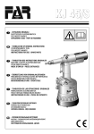
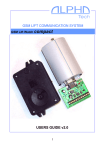
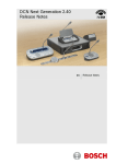
USER INSTRUCTIONS
Automax CENTURA™ CE Series
Electric Rotary Valve Actuator
FCD AXENIM0037-01 – 10/05 (Replaces AUTO-37)
Experience In Motion
Installation
Operation
Maintenance
Automax CENTURA™ CE Series FCD AXENIM0037-01 – 12/05
Introduction
The Centura electric actuator is a rotary valve actuator with output
torques from 250 to 1,500 in-lbs. It has been designed for NEMA 4, 4X,
7, 9 and can come with a 4-20 mA card for modulating service.
Storage
For short and long term storage refer to short and long term storage
conditions CE Actuator.
Maintenance
Centura Series actuators contain a permanently lubricated, precision
cut, heat treated gear train for long, reliable cycle life. There is no need
to change gear train grease; however, should it become necessary to
refill, use a multi-purpose grease such as DuBois MPG-2.
Permanent split capacitor gearmotors have been equipped with thermal
protectors. After many operations, especially in warm environments,
the motor will heat up. To guard the motor against overheating, the
thermal cut-out blocks power to the motor and maintains this state
until the motor’s temperature drops to a satisfactory level. This thermal
protection means that the actuator will not move when overheated.
Consideration must be given to the duty cycle requirements of the
actuator.
When replacing the cover, the machined joints must be clean and clear
of any obstructions. The integrity of the explosion-proof rating depends
on the care of these joints.
Installation
1. This section of the instruction sheet applies to the on-off units. For
instructions on Modulating units, please see the ESP3 Electronic
Servo Positioner Instructions.
2. Manually open and close valve to ensure freeness of operation.
a Caution: To prevent ignition of hazardous atmospheres,
keep unit tight while circuits are alive. Disconnect supply
circuit before opening.
3. Be sure valve and Automax actuator rotate in the same direction
and are in the same position (i.e., valve closed, actuator closed). If
not sure, electrically operate the actuator to determine its operating
range, taking note of any explosion safety requirement. The electric
actuators are factory set for 90 degree operation.
a Caution: Use heavy duty brake option ‘K’ for rubber lined
butterfly valves & dampers or applications that may back
drive the unit.
4. Mount Automax actuator to valve with Automax provided mounting
hardware to ensure proper alignment. Use mounting hardware
that has 11/2 times bolt length engagement. (Do not use the manual
override to align actuator shaft to valve shaft, as this could drive the
actuator out of its operating range).
NOTE: Some valves have manual stops; remove if appropriate or
set actuator to operate within those travel stops).
5. Care should be taken to align valve stem properly with Automax
actuator output shaft (misalignment will cause premature failure of
assembly).
6. To connect power to terminal strip of actuator, remove the cover
and locate the terminal wiring schematic inside the cover.
7. Connect power to terminal strip according to schematic diagram
(power should be fused with a 5 amp slow-blow fuse). The actuator
should be wired and grounded in accordance with Local and
National Electrical Codes.
a Caution: Consult factory when wiring multiple actuators
in series or parallel. Serious damage may result. User must
isolate unused winding.
8. Before replacing cover, actuate valve and check to see if it opens
and closes to preferred positions. If valve does not perform
correctly, adjust cams to set actuator travel properly.
9. Drive actuator to desired open position. The cams are adjusted in
two ways. Simply depress the splined “Quick-Set” cam against the
spring and rotate to desired location. Or, for very precise applications, turn the screw inside the cam to move the tip into the leaf of
the micro switch.
10. To adjust closed position, repeat step 9 with actuator in desired
closed position.
11. Operate the unit several times and recheck position. If unit is still
out of adjustment, reset the cams by following steps 9 and 10.
12. Installation in hazardous areas requires that the electrical leads be
sealed within 18 inches of the enclosure in accordance with Local
and National Electrical Codes.
13. Open conduit entries must be closed up after installation is
complete using a close-up plug engaging at least five full threads
and approved for use in hazardous locations.
Automax CENTURA™ CE Series FCD AXENIM0037-01 – 12/05
14. 60Hz actuator motors may be run on 50 Hz supply. However, the
cycle time increases by 1.2 times and the duty cycle decreases by a
factor of approximately 25%. The rated torque does not change.
Manual Override
The principle of the design is such that when the manual override shaft
is in the up position, the shaft is disconnected from the drive train.
When the shaft is in the down position it does two things. One, the shaft
trips a switch to disconnect the power to the motor and two, it releases
the brake. By releasing the brake the motor can back drive along with
the output. For 90 degree operation, the 250 in-lbs unit requires 1.6; the
700 in-lbs unit requires 3.1; the 1000 in-lbs unit requires 4.2; and 1500
in-lbs unit requires 6.3.
a Caution: Turn manual override shaft slowly. DO NOT jerk.
Manual Operation
1. The actuator cover should be securely attached.
2. Depress hub toward actuator cover.
3. Rotate the manual override shaft slowly; do not force.
4. The motor is now electrically disconnected.
5. Turn the manual override shaft clockwise for clockwise output.
6. Do not rotate actuator past full clockwise or counter-clockwise
position.
Automatic Operation
1. Pull hub away from the actuator cover.
2. The motor is now electrically connected and ready for automatic
operation.
3. The manual override shaft will freewheel.
Position Indication Stickers
Attached to the inside of the cover is a set of stickers with the words
“CLOSED” and “OPEN”. These stickers are to be attached to the outside
of the actuator near the base between the mounting feet. The stickers
have an orange triangle on them, such that when properly attached
to the actuator, they will line up with the triangle on the output shaft.
A sticker can be placed on either side of the unit to produce a visual
indication of the opened and closed position of the actuator.
flowserve.com
Automax CENTURA™ CE Series FCD AXENIM0037-01 – 12/05
Common Parts Related to All Actuators
No.
Item
Material
P/N
1
Painted Cover
Cast Aluminum
106100
1
2
5⁄16-24UNF HHCS/Shank
Stainless Steel
103233
8
3
5
⁄16 Type A Washer
Stainless Steel
103715
8
4
1/2" Sleeve Bearing
Sintered Bronze
105590
1
5
Molded Oil Seal
Nitrile
105585
1
6
Manual Override Hub
Black 141 Lexan
105567
1
7
7/16 I.D. Klipring
Stainless Steel
106174
1
8
Handwheel (Optional)
Black Plastic
105974
1
9
Manual Override Shaft
Steel/Plated
105591
1
10
Brake Trip Washer
Aluminum
107065
1
11
Manual Override Coupler
Steel/Plated
106129
1
Manual Override Spring
Spring Steel
105593
1
1
⁄16 Dia. Roll Pin
Spring Steel
103621
1
12
O-Ring, Base
N674-70 Nitrile
105584
1
13
CE1/CE2 Machined Base
Cast Aluminum
106098
1
CE4/CE7 Machined Base
Cast Aluminum
106099
1
CE5 Machined Base
Cast Aluminum
107503
1
⁄8" Needle Bearing
Steel/Plated
105582
1
14
3
15
3
⁄8" Sleeve Bearing
Sintered Bronze
105581
4
16
O-Ring, Output Shaft
N674-70 Nitrile
105583
1
17
11/2" Sleeve Bearing
Sintered Bronze
409944
1
18
CE1/CE2 Motor Plate
Cast Aluminum
106080
1
CE4/CE7 Motor Plate
Cast Aluminum
106081
1
CE5 Motor Plate
Cast Aluminum
107504
1
19
5
⁄8" Sleeve Bearing
Sintered Bronze
105694
1
20
8-32 UNC Ground Screw
Steel/Plated
103627
1
21
#8 Cup Washer
Brass
105626
1
22
8-32 UNC x ⁄8" Hex Screw
Steel/Plated
105577
5
23
8-32 UNC x 5⁄8" Phillips Hd.
Steel/Plated
105576
1
24
Actuator Bracket
Steel/Plated
108099
1
27
M.O. Cut-off Switch
Plastic/Steel
105769
1
28
Switch Insulator Gasket
Vulcanized Fiber
103675
5
29
4-40 UNC x ⁄8" Phillips Hd.S
Steel/Plated
106146
2
30
4-40 UNC x 11/4" Phillips Hd.
Steel/Plated
100159
2
31
3
⁄16" Higher Spacer
Nylon
105679
2
32
15 Amp Switch
Plastic/Steel
107765
2
33
3
⁄16" Pop-in Bearing
Plastic
105851
1
34
Camshaft
Steel/Plated
107005
1
35
Large 4-Deg. Spline Shaft
Plastic
103571
1
1
⁄16" Dia. Roll Pin
Spring Steel
103621
1
Small 4-Deg. Spline Shaft
Plastic
103572
1
1
⁄16" Dia. Roll Pin
Spring Steel
103621
1
37
Switch Spring
Spring Steel
103714
1
38
Hi-Ramp Cam
Plastic
107322
2
36
Qty
5
5
Continued on Page Automax CENTURA™ CE Series FCD AXENIM0037-01 – 12/05
Common Parts Related to All Actuators (continued from Page )
No.
Item
Material
P/N
39
CE2/CE4 Output Shaft Ass’y
Steel
106096
1
CE5 Ouput Shaft Ass’y
Steel
107700
1
CE1/CE7 Output Shaft Ass’y
Steel
106097
1
CE1/2/5/& 7 Offset Shaft
Steel 86L20
104864
1
1
⁄8 x 1⁄8 x 1.19" Long Key
Steel
105589
1
CE1 Offset Pinion
Steel -Heat Treated
104893
1
CE2 Offset Pinion
Steel -Heat Treated
104887
1
CE4 Offset Pinion
Steel -Heat Treated
104889
1
CE7 Offset Pinion
Steel -Heat Treated
104891
1
CE5 Offset Pinion
Steel -Heat Treated
107169
1
CE1/CE7 Offset Gear
Steel -Heat Treated
104890
1
CE2 Offset Gear
Steel -Heat Treated
104885
1
CE4 Offset Gear
Steel -Heat Treated
104884
1
CE5 Offset Gear
Steel -Heat Treated
107168
1
43
1.00 O.D.x 0.031 Spacer
Steel
105587
1
44
9
⁄16" I.D. Snap Ring
Spring Steel
100678
2
58
Nameplate
Stainless Steel
105578
1
Ty-Rap Cable Tie
Plastic
101066
2
3
⁄32" Dia. Drive Pins
Stainless Steel
105454
2
Cam Adjustment Sticker
Mylar
105757
1
Manual Override Sticker
Mylar
105756
1
Automax Logo Sticker
Mylar
105862
2
Position Indication Sticker
Mylar
106187
1
3/4" NPT Conduit Plug
Plastic
103685
1
Open/Close Stickers
Mylar
106186
1
59
Press Fit Washer
Steel
107178
1
60
Plug
Steel/Plated
107126
2
40
41
42
Qty
Additional Parts Specific To 115 VAC Actuators CE2, CE4, CE7, CE1, CE5
No.
Item
Material
P/N
49
115 VAC PSC Motor Int.
Steel/Copper
105675
1
16 Fin Impeller Fan
Plastic
105703
1
10-32 UNC x 3⁄16" SHCS
Steel/Plated
105599
2
54
Capacitor
Plastic Encapsulated
106619
1
55
Wire Tie
Plastic
106243
2
56
Quick Connect
Plastic/Steel
106761
4
25
6 Position Terminal Strip
Plastic/Steel
103997
1
2 Screw Marker Strip
Plastic
103996
1
3-48 UNC x 1/2" Pan Head
Steel/Plated
104837
2
115 VAC Wire Harness
Copper/Plastic
106111
1
115 VAC Schematic Sticker
Gloss Paper
815169
1
26
Qty
flowserve.com
Automax CENTURA™ CE Series FCD AXENIM0037-01 – 12/05
Automax CENTURA™ CE Series FCD AXENIM0037-01 – 12/05
flowserve.com
Automax CENTURA™ CE Series FCD AXENIM0037-01 – 12/05
Additional Parts Specific To 115 VAC With ESP Servo Positioner
Actuators Ce2ata, Ce4ata, Ce7ata, Ce1ata, Ce5ata
No.
Item
Material
P/N
Qty
No.
Item
Material
P/N
49
115 VAC PSC Motor Ext.
Steel/Copper
105676
1
49
12 VDC Gearmotor
Steel/Copper
106088
1
Fan Hub
Pressed Metal
107939
1
Motor Bracket Spacer
Aluminum
106193
2
Fan
Plastic
107940
1
6 Piston Terminal Strip
Plastic/Steel
103997
1
Compression Spring
Steel
108431
1
2 Screw Marker Strip
Plastic
103996
1
Brake Hinge Ass’y
Steel/Plastic
108600
1
3-48 UNC x 1/2" Pan Head
Steel/Plated
104837
2
Brake Solenoid
Coil
108022
1
12 VDC Wiring Harness
Copper/Plastic
106196
1
Switch Spring
Steel
103714
1
Wave Spring
Steel
108198
1
12 VDC Schematic
Sticker
Gloss Paper
815176
1
10-32UNF Set Screw
Stainless Steel
103486
1
.75 x .459 x .042 Washer
Brass
108361
1
Klip Ring
Stainless Steel
106174
1
No.
Item
Material
P/N
6-32 x 1/2 Phil. Screw
Steel
106061
1
49
24 VDC Gearmotor
Steel/Copper
106088
1
.350 x .118 Lg. Spacer
Bronze
108296
2
Motor Bracket Spacer
Aluminum
106193
2
6-32 Hex. Nut
Nylon/Steel
105864
1
10-32UNF SHCS
Steel
105599
2
6 Position Terminal
Strip
Plastic/Steel
103997
1
#6 Type A Plain Washer
Steel
100986
3
2 Screw Marker Strip
Plastic
103996
1
Brake Shim
Steel
108199
1
Steel/Plated
104837
2
8-32 x 5⁄8 Phil. Screw
Steel
105576
3
3-48 UNC x 1/2" Pan
Head
55
Wire Tie
Plastic
106243
2
24 VDC Wiring Harness
Copper/Plastic
106197
1
56
Quick Connect
Plastic/Steel
106761
4
24 VDC Schematic
Sticker
Gloss Paper
815176
1
54
Capacitor
Plastic
Encapsulated
106618
1
#6 x 0.19 lg. Spacer
Aluminum
100839
1
6-32 UNC x ⁄8"
Phillips Hd.
Steel/Plated
100881
1
1/4 Turn Standoff
Plastic
105168
2
ESP3 Servo Positoner
Fiberglass
105005
1
Potentiometer
Plastic
106195
1
85- Tooth Gear
Aluminum
107312
1
85- Tooth Gear
Aluminum
105853
1
115 VAC ESP3 Wire
Harness
Copper/Plastic
106194
1
ESP3 Schematic Sticker
Glass Paper
815224
1
52
3
26
Additional Parts Specific To 12 VDC Actuators Ce2b, Ce4b, Ce7b,
Ce1b, Ce5b
25
26
Qty
Additional Parts Specific To 24 VDC Actuators Ce2c, Ce4c, Ce7c,
Ce1c, Ce5c
25
26
Qty
Automax CENTURA™ CE Series FCD AXENIM0037-01 – 12/05
Wiring Diagrams
Reversible DC Actuator
a Caution: To prevent ignition of hazardous atmospheres, keep
unit tight while circuits are alive. Disconnect supply circuit
before opening.
a CAUTION: Consult factory when wiring multiple actuators in
series or parallel. Serious damage may result.
NOTE: Wiring diagrams show internal wire connections and suggested
customer connection for proper use. Switches shown in “customer
wiring” are for illustration only and are not supplied with the actuator.
Reversible AC Actuator
Reversible AC Actuator with 2 Extra Switches
Reversible Modulating AC Actuator
flowserve.com
Automax CENTURA™ CE Series FCD AXENIM0037-01 – 12/05
Typical Actuator Specifications
Action
Reversible
Range of Adjustability
Supply Voltages
0° -270°
AC:
115 VAC
+/-10%
230 VAC
50/60 Hz
24 VAC
DC:
12 VDC
24 VDC
Temperature Rating
-40°F (-40°C) to 160°F (70°C)
Enclosure Ratings
Nema 4, 4X, 7, 9 Watertight and Explosion-proof
Class I Groups C&D, Div. 1&2
Class II Groups E, F&G, Div. 1&2
Motor Types
AC:
Permanent Split Capacitor, Class B Insulation
DC:
Brush
AC Motor Thermal Protection
Automatically resetting
Travel and Aux. Switches
SPDT, Form C
15 amp 125 VAC 1/2 HP, 10 amp 250 VAC, 1/2 amp 125 VDC
Conduit Connections
3/4-14 NPT
Manual Override
300 In-lbs max input
Corrosion Protection
Chromate conversion undercoat with polyester electrostatic powder top coat
Terminal Strip Hookup
300V, 30 amp, 12-26 AWG
Lubrication
Permanently lubricated
Gear Train
Heat treated alloy steel able to withstand stall torque
Note: The above ratings may change depending on model configurations and options provided. Products may
differ as the result of the Company policy of continuous product improvement.
Motor
Option
Motor
Voltage
Duty
Cycle (1,3)
Std.
115 AC
25
A
115 AC
Extended: 75
B
12 DC
100
C
24 DC
100
D
230 AC
25
F
230 AC
Extended: 75
J
24 AC
100
Torque and Weights
Torque (In-Lbs)
Torque (N-M)
Weight (Lbs)
Weight (Kg)
Notes:
Run
Current
(Amps)
Locked
Rotor
(Amps)
1.1
0.5
1.6
0.9
0.7
0.3
0.5
1.3
0.6
3.0 (2)
2.0 (2)
0.8
0.4
0.8
Cycle Times in Seconds per 90 Degrees
Actuator Model
CE2
CE4
CE7
CE1
CE5
3
5
6
11
18
6
10
17
24
36
6
9
16
21
32
6
8
15
20
30
3
5
6
11
18
6
10
17
24
36
3
5
6
11
18
250
28
18
8
400
45
18
8
700
79
18
8
1000
113
18
8
1500
169
20
9
1. Duty cycle is the limit of “on” time as percentage of total cycle time. For example, the CE2 with standard motor
runs 3 seconds to open or close the valve. The motor must remain off for 9 seconds prior to starting the close
cycle. DC motors may be operated continuously.
2. Do not lock up DC motors.
10
3. CE5 duty cycles for AC motors are 20% for standard duty and 70% for extended duty.
4. For 180 degree applications, simply multiply the above cycle times by 2.
Automax CENTURA™ CE Series FCD AXENIM0037-01 – 12/05
Troubleshooting
Problem
There is power to the unit, but it does not respond.
Solution
Check the nameplate to see that the correct voltage has been applied.
Check the wiring to see that it is per the wiring schematic.
Check the limit switches to see if they are in the normal operating
range.
Check the manual override. If it is in the down position, the motor is
electrically disconnected.
Problem
Power is getting to the motor, but it merely hums.
Solution
Check to see that the proper voltage is applied. Make sure all the
connections are tight.
Check to see that the brake coil is pulling the brake pad and hinge away
from the fan.
Check to see that CW and CCW power connections are not powered at
the same time.
Problem
The actuator performs erratically.
Solution
Check to see that the actuator is not stalling.
Check the ambient temperature rating. The permanent split capacitor
units are equipped with thermal cut-outs. Excessive temperatures and
cycle frequencies may heat the motor up and the thermal cut-out turns
it off.
11
flowserve.com
United States
Flowserve Corporation
Flowserve Flow Control
1978 Foreman Drive
Cookeville, TN 38501
Tel 931 432 4021
Fax 931 432 5518
FCD AXENIM0037-01 Printed in USA. (Replaces AUTO-37)
To find your local Flowserve representative:
For more information about Flowserve Corporation, visit
www.flowserve.com or call USA 1 800 225 6989
Flowserve Corporation has established industry leadership in the design and manufacture of its products. When properly selected, this Flowserve product is designed to perform its intended
function safely during its useful life. However, the purchaser or user of Flowserve products should be aware that Flowserve products might be used in numerous applications under a wide
variety of industrial service conditions. Although Flowserve can (and often does) provide general guidelines, it cannot provide specific data and warnings for all possible applications. The purchaser/user must therefore assume the ultimate responsibility for the proper sizing and selection, installation, operation, and maintenance of Flowserve products. The purchaser/user should
read and understand the Installation Operation Maintenance (IOM) instructions included with the product, and train its employees and contractors in the safe use of Flowserve products in
connection with the specific application.
While the information and specifications contained in this literature are believed to be accurate, they are supplied for informative purposes only and should not be considered certified or as
a guarantee of satisfactory results by reliance thereon. Nothing contained herein is to be construed as a warranty or guarantee, express or implied, regarding any matter with respect to this
product. Because Flowserve is continually improving and upgrading its product design, the specifications, dimensions and information contained herein are subject to change without notice.
Should any question arise concerning these provisions, the purchaser/user should contact Flowserve Corporation at any one of its worldwide operations or offices.
© 2005 Flowserve Corporation, Irving, Texas, USA. Flowserve is a registered trademark of Flowserve Corporation.
flowserve.com