1
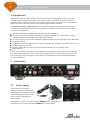
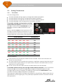
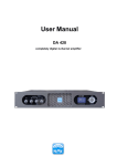
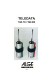
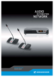
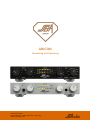
ADICON Connecting and Operating SSB Audio GmbH Sonnenweg 25 – 30827 Garbsen – Germany www.ssb-audio.com Page 1 ADICON – Connecting and Operating Contents 1 SAFETY GUIDELINES – READ BEFORE USING! ................................................................................. 3 2 Introduction ........................................................................................................................................ 4 3 Connection .......................................................................................................................................... 4 3.1 Power Supply ........................................................................................................................... 4 3.2 Analog Connections ................................................................................................................ 5 3.2.1 Turntables ................................................................................................................................ 5 3.2.2 Tape Recorder Input/Output ................................................................................................. 6 3.3 Digital Connections ................................................................................................................. 6 3.3.1 Digital Outputs ......................................................................................................................... 6 3.3.2 USB Port.................................................................................................................................... 6 3.3.3 PC Connection via S/PDIF or Toslink ..................................................................................... 7 3.3.4 The Earth or Hum Loop Problems, Particularly with USB Ports ....................................... 8 4 Operation ............................................................................................................................................ 9 4.1 Input Selection and Input Sensitivity .................................................................................... 9 4.2 Peak Program Meter, PPM ................................................................................................... 10 4.2.1 (S)PPMs and VU-Meter .......................................................................................................... 10 4.2.2 Why Optimum Level Control? .............................................................................................. 10 4.2.3 The Peak Hold Function ........................................................................................................ 11 4.2.4 LED Brightness ....................................................................................................................... 12 4.3 Sample Rate ........................................................................................................................... 12 4.4 Headphone Output ............................................................................................................... 12 5 Technical Data .................................................................................................................................. 13 5.1 5.1.1 Inputs ...................................................................................................................................... 13 5.1.2 Outputs ................................................................................................................................... 13 5.1.3 USB .......................................................................................................................................... 13 5.1.4 Power Supply ......................................................................................................................... 14 5.2 ADC .......................................................................................................................................... 14 5.3 Measured Values ................................................................................................................... 14 5.3.1 Frequency Response ............................................................................................................. 14 5.3.2 Frequency Response PHONO .............................................................................................. 14 5.3.3 Distortion and Crosstalk ....................................................................................................... 15 5.3.4 S/N Ratio ................................................................................................................................. 15 5.4 6 Connections ........................................................................................................................... 13 Housing ................................................................................................................................... 16 Getting Started with Audacity......................................................................................................... 17 Page 2 ADICON – Connecting and Operating 6.1 Installation .............................................................................................................................. 17 6.2 Selecting the Recording Device ........................................................................................... 17 6.2.1 Connection via the USB-Interface ....................................................................................... 17 6.2.2 Connection Via S/PDIF Resp. Toslink .................................................................................. 18 6.2.3 Project Rate ............................................................................................................................ 18 6.2.4 Pre-listening ........................................................................................................................... 18 6.3 Recording ............................................................................................................................... 18 6.4 Pre-Listening While Recording ............................................................................................. 18 6.5 Listening in Already Recorded Audio Tracks ..................................................................... 19 6.6 Playback .................................................................................................................................. 19 6.7 Editing Recordings ................................................................................................................. 19 6.7.1 Selecting Time Periods ......................................................................................................... 19 6.7.2 Zooming .................................................................................................................................. 19 6.7.3 Cutting..................................................................................................................................... 19 6.7.4 Modifying Single Samples .................................................................................................... 19 6.7.5 Separate Recordings into Several Audio Tracks ................................................................ 19 6.7.6 Fade In and Out ..................................................................................................................... 21 6.7.7 Normalize ............................................................................................................................... 21 6.7.8 Save an Audio Track or a Part of an Audio Track to File .................................................. 22 6.8 Further Functions .................................................................................................................. 22 Page 3 ADICON – Connecting and Operating 1 SAFETY GUIDELINES – READ BEFORE USING! The device meets protection class 2 and has left the factory in a technically faultless state. In order to assure this state and to insure riskless operation the user must obey the notes and warnings which are part of this manual. SAFETY, RELIABILITY AND PERFORMANCE OF THIS DEVICE ARE GUARANTEED ONLY WHEN: Installation, expansions, modifications and repairs are accomplished only by the manufacturer or by personal authorized by the manufacturer. The electrical installations of the relevant room meet the corresponding IEC (ANSI) requirements. The device is used in accordance with this user manual. POWER SUPPLY The device is designed for continuous operation. The power supply’s operating voltage must meet the local line voltage. Avoid connections to the power supply system in junction boxes together with many other devices. The electrical outlet needs to be installed close to the device and easily accessible. Use the supplied power supply unit. Other power supplies may cause malfunctions or even damage the device. INSTALLATION SITE The device should stand only on clean horizontal work surfaces or be installed in a suitable rack. During operation the device must not be exposed to vibration. Humidity, liquids of all kinds and dust must be kept away as far as possible. Sufficient ventilation needs to be provided. Avoid direct sunshine and the proximity of radiators and radiant heaters. IMPORTANT NOTE Computers are highly complex systems. Their behavior is not always explainable and not always reproducible. Particularly in the case of cooperation with external hardware applications work in some cases only after extensive tests and possibly further measures. The number of possible obstacles is enormous, sometimes insurmountable obstacles also arise. The application software is complex, too, and if important settings are incorrect or operating procedures are unclear in the software, another source of alleged malfunctions arises. Therefore, the responsibility for the correct operation of the entire system is with the user. SSB AUDIO GmbH cannot take over this responsibility. The ADICON has been successfully tested with several computers, operating systems and recording programs. Page 4 ADICON – Connecting and Operating 2 Introduction Many now historic, but high-quality sound sources from the analog time, that is to say tape recorders and turntables, meanwhile do not only scrape an existence as visual museum or collector’s items anymore, but they are actively operated (again). The desire for an appropriate digital connection of these devices to the modern digital world is obvious. The ADICON (Analog-to-Digital Converter) was specially designed to provide this missing link. This ADC is equipped with special inputs and outputs and other functions that are necessary or useful for this application: Two inputs (RCA), both individually adjustable in their sensitivity For one of the inputs an RIAA preamplifier can be activated so that it also can be used as turntable input (moving magnet, moving coil on demand) The other input can also be accessed via its DIN connector for tape recorders with a DIN cable. Line output (RCA) Headphone output for operation as a separate headphone amplifier or to preview the source Level indicator for the ADC Digital outputs optical (Toslink) and coaxial (RCA, S/PDIF), 44.1 to 192 kHz, 24 bit USB interface The connection and the operation of the ADICON are quite obvious with only a few exceptions. This should particularly be true for those users who have been concerned for many years with the technology of their equipment. But at least for the digital part some valuable information could be found here. 3 Connection 3.1 Power Supply The included 12-volt power adapter can be connected to the ADICON with a lockable connector. Rotate the plug clockwise so that that it cannot accidentally be disconnected. The ADICON is turned on by pressing the POWER switch. The operation is indicated by the illumination of one of the two LEDs SOURCE on the front panel. Page 5 ADICON – Connecting and Operating 3.2 3.2.1 Analog Connections Turntables It is to be distinguished: Turntable with MM (moving magnet) cartridge without RIAA preamplifier Turntable with MC (moving coil) cartridge without RIAA preamplifier Turntable with MC cartridge with transformers without RIAA preamplifier Turntable with MM or MC cartridge with its own RIAA preamplifier A turntable with MM (moving magnet) cartridge without RIAA preamplifier is connected to the RCA jacks IN 1. The push button AUX/PHONO must be pressed to activate the RIAA preamplifier in the ADICON. With the switches LOAD the load capacitance of the cartridge recommended by its manufacturer is set. This load capacitance affects the frequency response at high frequencies. The minimum load capacitance of the ADICON is 100 pF. Switch Positions Load Capacity 1 2 3 4 5 6 pF OFF OFF OFF OFF OFF OFF 100 ON OFF OFF ON OFF OFF 150 OFF ON OFF OFF ON OFF 200 ON ON OFF ON ON OFF 250 OFF OFF ON OFF OFF ON 300 ON OFF ON ON OFF ON 350 OFF ON ON OFF ON ON 400 ON ON ON ON ON ON 450 Note the following: Load capacitors may already be installed into the turntable. These have to be taken into account or to be removed. The audio cable from the turntable also represents a significant capacitive load that must be considered. With a good cable you can expect about 100 pF/m. Unsuitable cables can have capacitances of up to 500 pF/m. For this reason the audio cable from the turntable should never be extended! A turntable with MC (moving coil) cartridge without RIAA preamplifier is also connected to the RCA jacks IN 1, but instead of an MM RIAA preamplifier an RIAA preamplifier for MC cartridges (option) must be installed in the ADICON. The push button AUX/PHONO must be pressed to activate the RIAA preamplifier in the ADICON. The properties of MM and MC cartridges and preamps are very different. MM preamps have an approximately 10 times higher gain, a very small input impedance and do not need an external load capacitance. Page 6 ADICON – Connecting and Operating A turntable with MC cartridge with transformers without RIAA preamplifier is connected like a turntable with MM (moving magnet) cartridge without RIAA preamplifier to the input IN 1. The push button AUX/PHONO must be pressed to activate the ADICON’s RIAA preamplifier. Turntables with MM or MC cartridges with their own RIAA preamplifiers can be connected to IN 1 as well as to IN 2. The push button AUX/PHONO is not pressed. 3.2.2 Tape Recorder Input/Output A tape recorder is preferably connected to its designated input IN 2, but it can also be connected to IN 1. Thus two tape recorders can be connected simultaneously to the ADICON. When connected to IN 2 the RCA jacks IN 2 can be used for the playback signal and the RCA jacks LINE for the record signal or the common DIN socket TAPE IN/OUT can be used for both signals. IN 2 and TAPE IN/OUT must not be used at the same time. When connected to IN 1 the RCA jacks IN 1 are used for the playback signal and the RCA jacks LINE for the record signal. The push button AUX/PHONO is not pressed. 3.3 3.3.1 Digital Connections Digital Outputs Both digital outputs deliver the same signal and can be used simultaneously. The S/PDIF output is equipped with an isolation transformer. Thus hum loops caused by the coaxial cable are avoided. Particularly for the operation of a turntable and an exclusively digital connection to the hi-fi system it may prove necessary that the ADICON or, e.g., the turntable must be connected to ground or protective earth to avoid hum troubles. The ADICON provides a corresponding ground screw. 3.3.2 USB Port There is a combined USB Audio Class 1/2 interface available, being able to transfer sample rates of 44.1, 48, 88.2 and 96 kHz at 24 bit as well as 176.4 and 192 kHz at 16 Bit resolution (USB Audio Class 1) and 176.4 und 192 kHz at 24 bit resolution (USB Audio Class 2). Note: Microsoft Windows® only supports USB Audio Class 1, so that in Windows operating systems the sampling rates of 176.4 and 192 kHz are available with 16 bit resolution only. Apple OS X® (from 10.6, Snow Leopard) and Linux also support USB Audio Class 2, so that all sample rates listed above are available at 24 bit resolution. When connecting to the USB host (e.g., a PC or notebook) the ADICON is reported as another audio device labeled ADICON-XXXXX Hz where XXXXX indicates the sampling rate set at the ADICON. If the sampling rate is changed at the ADICON it logs off and after a few seconds logs on again as another audio device with the new sampling rate and appropriate different name. Page 7 ADICON – Connecting and Operating In case of Windows and at sample rates greater than 96 kHz ADICON XXXXXX kHz/16 will be indicated. The time until the ADICON logs on again as an audio device after it has been connected for the first time to a Windows PC will be prolonged by another 30 seconds. It is not necessary to install any drivers. This device is only intended for recording on the PC. Playback must take place using a different audio device on the PC. Note: This means that the signal from the ADICON via USB is not directly audible under normal circumstances, i.e., it is not available in the playback control. The signal can solely be recorded and is audible only during playback. This is caused neither by the ADICON nor by the operating system of the PC. It is caused principally by the digital technology and is because a correct reproduction of audio signals produced in real time (e.g., by an ADC like the ADICON), is possible only when the clocks of ADC and DAC run exactly synchronously. Due to the USB interface the precise timing of the source gets lost in the PC. If playback through another audio device (i.e., another DAC necessarily running with another asynchronous clock) is possible at all, it is therefore only possible with compromises. For that buffers are usually introduced which on the one hand cause a delay in the output and, secondly, overflow or underflow over time due to the asynchronous clocks. As a rule this leads to discarding a complete buffer content at overflow or to a repetition at underflow causing significant disturbances in the signal. Often such a way is therefore not even provided. Depending on the operating system and any application program, the audio signal from the ADICON can at least be made visible on the PC, where appropriate, with a level meter. Also, the program AUDACITY further mentioned below shows the audio level in recording mode with the correct setting. AUDACITY even offers the opportunity to output the signals from the ADICON with the delay caused by the buffer and the possible overflow and underflow via another audio device. The green LED C signals that a USB host is connected. The green LED S signals by slow flashing that the ADICON is ready for data transmission. It does not signal that the data transmission actually works or that a host is connected. It is constantly illuminated when data transfer is taking place. It indicates by double-flashing that a connection to a Windows PC at 176.4 or 192 kHz is established. It goes out briefly when the sampling rate is changed on the ADICON. In order to avoid annoyance flashing is terminated after 3 minutes when no change of state was encountered. If needed, we recommend the free program AUDACITY for recording, editing and playback of files (http://audacity.sourceforge.net/) which is available for Windows®, OS-X® and Linux. This program offers a great deal more than simply recording an audio signal. A brief introduction can be found at the end of this manual. Note: SSB AUDIO GmbH cannot take over the system responsibility for ensuring that your computer or software, in particular in cooperation with the ADICON, is working properly. 3.3.3 PC Connection via S/PDIF or Toslink PCs can be linked directly to the ADICON via S/PDIF or Toslink or by using the USB port. Both have advantages and disadvantages. If the ADICON is digitally connected via S/PDIF or Toslink to a PC, the restrictions concerning the simultaneous playback of the audio signal on the PC listed in the previous chapter 3.3.2 USB Port Page 8 ADICON – Connecting and Operating do not apply, even if the connection is made via an external USB interface which allows simultaneous recording and playback. However, it must be expected that the audio data is changed that way without the user being able to recognize it. The audio can be resampled and/or changed in amplitude. It is a good sign and a minimum requirement if the record level control is not adjustable, because if it is adjustable, it is almost certain that the audio data is changed in amplitude. Aside from that, the indication of the ADICON’s level meter is not necessarily valid in such a case. Undesirable resampling cannot easily be recognized. Depending on the system, it may be necessary that the sampling rate on the PC must be set equal to that on the ADICON. Unfortunately we can give no more than such vague tips here, at best the simple advice: "For more information, ask your system administrator, study the manuals of your system components or conduct intensive behavioral research on your system." 3.3.4 The Earth or Hum Loop Problems, Particularly with USB Ports General background information Often the sound in hi-fi systems is interfered with so-called ground or hum loops. Put simply, this phenomenon arises especially when the signal grounds of the individual components of a system are connected to at least two different points to the protective earth. Hi-fi components in the home are not usually grounded to earth, but are usually connected to the protective earth via the antenna connection of the tuner. This single connection to protective earth is not only harmless, it may even be important and prevent hum of another kind. A problem arises when a second device that also has a connection to protective earth is connected to the hi-fi system. This can be a TV set with its antenna connection or an earthed PC, for example. Then so-called equalizing currents flow through the signal masses of the audio cables that are superimposed on the signal voltage and jam it. The compensation currents are really critical where they flow through analog audio cables. There, however, where they flow, e.g., through antenna cables, power cables, digital lines or network cables, they are relatively harmless. The ADICON’s special situation So beside the antenna connector the second connection to protective earth could be a grounded PC which is connected via USB to the ADICON and from there via analog audio cable to the hi-fi system. The above sentence must be read carefully: It says that exactly three conditions for a ground loop must be met: 1. The hi-fi system is already earthed at one point, e.g., via the antenna. 2. The PC (or a device connected to the PC) is grounded as well. That is common, only in netbooks or notebooks this might not be the case. 3. The ADICON is not only digitally, but also via an analog cable (typically at ADICON output LINE) connected to the hi-fi system. On point 3: However, a solely digital connection, optical or coaxial, between the ADICON and the hi-fi system is completely harmless, because the optical output OPTICAL is isolated by nature and the coaxial output S/PDIF of the ADICON is equipped with an isolation transformer which prevents earth loops reliably. In a purely digital connection so to speak two mutually insulated earthed „islands“ are formed: The hi-fi system, earthed via the antenna of the tuner, and the Page 9 ADICON – Connecting and Operating ADICON with its sources, grounded via the USB cable to the PC. (Even if the digital connection did not separate, the compensating current flowing in that case would probably be harmless, because it does not flow over an analog audio cable.) Conclusion to avoid earth loops It is sufficient when one of the above three conditions is not satisfied: 1. When the antenna is disconnected or connected via an isolating transformer. 2. When a notebook or netbook which is not connected to protective earth is used. But it must also not be linked to a further device, e.g., a monitor or printer, or via a network cable connected to protective earth! 3. When the ADICON is connected exclusively digital to the hi-fi system. This condition is easily met. Another example: If, e.g., a tuner (set-top box, TV) was linked additionally to an ADICON connected to protective earth via USB, a ground loop would probably arise again via the antenna or network connection of the devices. The compensating current over the analog connection cable caused by that would probably disturb the sound of these devices. 4 Operation 4.1 Input Selection and Input Sensitivity The push button SELECT is used to select between the inputs IN 1 and IN 2. The selected input is indicated by the corresponding LED. The sensitivity can be set separately for each input with the corresponding potentiometers IN 1 or IN 2 respectively. This setting is not thought of as volume control according to custom, where the signal can be reduced to total silence. Instead, the gain of the input stage can only be set in a range from -10 dB to +20 dB. Page 10 4.2 ADICON – Connecting and Operating Peak Program Meter, PPM The sensitivity of the inputs should be adjusted so that the ADC does not overdrive in any case. Not because that would mean a physical danger to it, but because otherwise distortions by cutting the voltage spikes, known as clipping, would arise. On the other hand, it should not be set too low. 4.2.1 (S)PPMs and VU-Meter For level metering a digital so-called Peak Program Meter (PPM) is provided which measures the digital data stream and not the analog signal. That is why there are no positive values on its scale, because the signal is either within limits or it is clipped, but a digital signal cannot exceed its range of numerical values. Clipping is indicated by the red LEDs CLP. With the VU meters, customary in tape recorders, it is totally different: There is no distinct limit on tape recorders. With a rising level only the harmonic distortions increase moderately, so that overdriving, particularly at short peaks, hardly carries any weight. Full scale in tape recorders depends more on the trade-off between dynamic range and distortion and is, in contrast to the level control of digital signals, relatively arbitrary. A PPM is different from VU meters also in that it reacts much faster to voltage spikes. In particular, the variant used here, a so-called sample PPM (SPPM) takes into account each sample in full. Its attack time is practically 0. 4.2.2 Why Optimum Level Control? In principle it would be possible to make the inputs so insensitive that the ADC cannot be overdriven under any conditions. It would then normally be modulated only slightly, but in contrast to, e.g., a tape recorder in which a low level control reduces the dynamic range, the inherent noise of a modern ADC like the ADICON is so low that this effect does not matter in practice. This is particularly true in connection with tape recorders and turntables. There is a more important reason for optimum level control: The ADICON will probably not be the only (digital) source in the audio system. When its signal is played back, its loudness should not differ much from the loudness of other sources, e.g., CDs. Thus the ADICON should be set or modulated accordingly. Some background information: Many CDs are modulated in a way that the loudest passages or the highest voltage spikes just reach the technical maximum. The full scale range (FS) is used to 100%. This is called a level of 100% FS. As this can hardly be done manually, the whole recording is searched for the loudest passage on a computer before the mastering and subsequently the gain is set so, that this passage is recorded just with 100% FS. This is called normalizing and it is often also combined with a more or less strong compression, so that full scale may occur not only once, but also even very often. It speaks well for the producer, when his production is not as loud as possible, but when the original dynamic range is maintained and when he does not go for the limits of the full scale range. Page 11 ADICON – Connecting and Operating When the level is to be adjusted it is of course usually impractical or even impossible to determine the loudest passage in advance. So you have to work with a corresponding safety margin. This safety margin is individual, it depends on the program material as well and a little bit on the user’s experience. As a reference value the following could be specified: A level control of program material coming from a CD which is permanently maximally modulated as described above is easily and safely possible until shortly before clipping. The -2 dB LED would flare quite frequently, but only briefly at a time. That applies to the orange section of the LEDs. Recordings with greater dynamic should perhaps first be modulated with -8 dB max., that means in the yellow section of the LEDs, in the hope that no 8 dB higher peaks occur. Out of purely technical reasons you can be much more confident that with voice, transmitted via radio, no particularly high peaks will occur, which is completely different to recordings from a child’s birthday party. 4.2.3 The Peak Hold Function Often a peak hold function where a measured peak value is displayed over a certain time by an illuminated LED proves to be useful. Because you do not have to look so closely, short peaks can be recognized easier. The peak hold time is set with the switches 1 and 2 of the 4 switches SET on the rear of the ADICON according to personal preferences: Switch Position Time (s) 1 2 OFF OFF Off* ON OFF 1 OFF ON 3 ON ON 10 *Note: Description Advantage: Even a short flare of individual peak values can be recognized A common peak hold time Leaves more time during which you do not have to keep an eye on the level control Leaves an extreme amount of time during which you do not have to keep an eye on the level control In position OFF the red LEDs CLP also have peak hold functions of 1 second (more precisely: Clip hold functions). Page 12 ADICON – Connecting and Operating 4.2.4 LED Brightness The LEDs can be adapted in their brightness to the user’s individual preferences in 4 relatively big steps. The setting is done with the switches 3 and 4 of the 4 switches SET on the rear of the ADICON: Switch Position Brightness 3 4 OFF OFF 100% ON OFF 25% OFF ON 6% ON ON 1.5% 4.3 Sample Rate The sample rate (SAMPLE RATE) can be set to the most common values between 44.1 kHz and 192 kHz.44.1 kHz is used with CDs, 48 kHz among others with DVDs. Higher sample rates are rather found in sound studios. They allow for a higher signal bandwidth. There are no disadvantages when working with higher sample rates, e.g., between the ADICON and an amplifier with digital input or a DAC, as long as this device supports the higher sample rate. Of course, more memory space is needed for the recording of such signals. For operation via the internal or an external USB interface please regard the information in the chapter USB. 4.4 Headphone Output The headphone output is equipped with an individual volume control adjustable with the potentiometer VOLUME. All common headphones can be connected to the output PHONES. For headphones with a 3.5 mm jack a ¼” adapter is required. Caution: Compared to headphone outputs, e.g., in hi-fi systems, this output supplies a significantly higher volume as common in professional practice. The gain of the headphone amplifier was chosen so that it does not overmodulate as long as the red CLP LEDs are not illuminated. Strictly speaking, this is true only for headphone impedances greater than 300 ohms approximately, as usually found in headphones for hi-fi systems. Head phones for professional applications often have significantly lower impedances. However, their output signals always remain undistorted at modulations to about -1 dB. Page 13 ADICON – Connecting and Operating 5 Technical Data (Errors and technical modification subject to change) 5.1 Connections 5.1.1 IN 1 Inputs Type: RCA Usage: Phono, Tape, Aux Input voltage at full scale (100% FS) = 2 VRMS at output LINE: Switch PHONO/AUX in position PHONO, MM: Switch PHONO/AUX in position PHONO, MC: Switch PHONO/AUX in position AUX: IN 2 Type: RCA and DIN Usage: Tape, Aux Input voltage at full scale (100% FS) = 2 VRMS at output LINE: RCA jacks: DIN socket: 200 mVRMS to 6 VRMS 200 mVRMS to 6 VRMS Control range of the gain for IN 1 and IN 2: 5.1.2 LINE 2 mVRMS to 60 mVRMS 0.2 mVRMS to 6 mVRMS 200 mVRMS to 6 VRMS -10 dB to +20 dB Outputs Type: RCA and DIN Output voltage at full scale (100% Full Scale): RCA jacks: DIN socket: 2 VRMS 100 mVRMS PHONES Type: Usage: Output voltage: Output impedance: TRS jack, ¼” Headphone output on the front panel Max. approx. 6.4 VRMS unloaded 47 Ω S/PDIF Type: Usage: Output impedance: Output voltage: Format: RCA, transformer-coupled Output digital audio signal coaxial 75 Ω 1 VPP at 75 Ω load Consumer, no copyright protection (C=1, L=0) TOSLINK Usage: Format: Output digital audio signal optical Consumer, no copyright protection (C=1, L=0) 5.1.3 USB Connection USB Audio Class Power Supply Receptacle type B USB Audio Class 1 up to 96 kHz / 24 Bit USB Audio Class 1 at 176.4 and 192 kHz / 16 Bit (Windows) USB Audio Class 2 at 176.4 and 192 kHz / 24 Bit (OS X and Linux) Self powered device, max. power consumption from USB 20 mA Page 14 ADICON – Connecting and Operating 5.1.4 Power Supply Connector: Low-voltage connector (barrel jack) 5.5/2.1 mm, lockable Operating voltage: 12 VDC Current consumption: Full scale, no headphone: 350 mA approx. Full scale, max. with headphone: 800 mA approx. 5.2 ADC Sample rates: 44.1 kHz, 48 kHz, 88.2 kHz, 96 kHz, 176.4 kHz, 192 kHz Resolution: 24 Bit 5.3 Measured Values 5.3.1 Frequency Response Settings: Input: Gain: Input voltage: Output: IN 1 or IN 2 0 dB 1.8 VRMS approx. (equivalent to -1 dB FS) digital Readings: Sample rate 96 kHz (refer also to the following figure): Approx. 2 Hz to 48 kHz < +0/-3 dB Approx. 10 Hz to 43 kHz < +0/-0.2 dB Sample rates < 96 kHz: Upper cut-off frequencies proportionally reduced Sample rates 176.4 and 192 kHz: Upper -3 dB cut-off frequency: Upper -0.2 dB cut-off frequency: 5.3.2 Approx. 69 kHz resp. 76 kHz Approx. 48 kHz resp. 52 kHz Frequency Response PHONO Corresponding to RIAA standard plus 7 Hz high-pass filter Deviation +/-0.5 dB max. (typ. +/-0.2 dB) in the range of 20 Hz to 20 kHz) Page 15 5.3.3 ADICON – Connecting and Operating Distortion and Crosstalk Settings: Input: Gain: Left channel: Right channel: Output: Readings: (Refer also to the following figure) Distortion: 0.00015% (-116 dB) at 1 kHz and -3 dB FS Crosstalk: -103 dB approx. at 1 kHz 5.3.4 IN 1 0 dB Signal 1 kHz Sine, level –3 dB FS (equivalent to 1.4 VRMS approx.) Level 0 V, input terminated at low Digital at 96 kSa/s sample rate S/N Ratio Settings: Input: Level: Output: Readings: Gain (dB) -10 0 +10 +20 IN 1 0 V, input low-impedance terminated Digital at 96 kHz sample rate ANSI-A 110 dB 109 dB 107 dB 98 dB 20 Hz to 22 kHz linear 108 dB 107 dB 105 dB 96 dB Page 16 5.4 ADICON – Connecting and Operating Housing Material: Steel, powder-coated surface, front panel 5 mm aluminum Dimensions: Depth: Width: Height: Height: Weight: ADICON: 1455 g incl. phono preamp and USB interface Power supply: 160 g 172 mm without connectors, incl. control elements 219 mm 40 mm without stands 50 mm with stands Page 17 ADICON – Connecting and Operating 6 Getting Started with Audacity Audacity is a free open source software for professional recording, editing and playback of audio signals and provides much more functions than within the scope of the usual use of the ADICON is required. The huge number of functions is not only advantageous, it may also cause confusion for a beginner so that a start becomes more difficult than necessary. Other recording software is generally not free but offers in return a wider range of functions. Corresponding to our experiences, for this but also for other reasons it is sometimes significantly more difficult to learn to know in these programs. This is why we present a short introduction to Audacity and its most important functions here. Note: Computers are highly complex systems. Their behavior is not always explainable and not always reproducible. Particularly in the case of cooperation with external hardware applications work in some cases only after extensive tests and possibly further measures. The number of possible obstacles is enormous, sometimes insurmountable obstacles also arise. The application software is complex, too, and if important settings are incorrect or operating procedures are unclear in the software, another source of alleged malfunctions arises. Therefore, the responsibility for the correct operation of the entire system is with the user. SSB AUDIO GmbH cannot take over this responsibility. The ADICON has been successfully tested with several computers, operating systems and recording programs. 6.1 Installation ® ® Audacity is available for Windows , OS X (from 10.6, Snow Leopard on) and Linux. ® When it is installed on OS X 10.9.5 and higher it may happen that the start of the installation will be blocked because the identity of the developer cannot be verified. In case that the program has been downloaded from a trustworthy source the installation process can be resumed without fearing negative consequences. In this case you need to: 1. 2. 3. 4. Confirm the message with OK. Click on AUDACITY.dmg once more but this time with the right mouse button. In the context menu that appears shortly afterwards click on “Open“. The same message appears again, but this time you are asked whether you really want to open the application. 5. Confirm this by clicking on “Open“. Then the installation will start. After the installation of Audacity all except a few settings are so that you can directly work with it. 6.2 Selecting the Recording Device 6.2.1 Connection via the USB-Interface When the ADICON is connected through its USB-interface before Audacity has been started it can resp. must be selected as a recording device in the drop down box beside the microphone symbol. Page 18 ADICON – Connecting and Operating When the ADICON is connected through its USB-interface after Audacity has been started it must first be introduced to Audacity before it can (and must) be selected as a recording device: Transport Rescan Audio Devices. The same applies when the sample rate at the ADICON is changed. In this case the ADICON logs off from the operating system and logs on again after a couple of seconds with a new name. Only then the “new“ ADICON is available as recording device in the drop down box beside the microphone symbol. Note: In case of Windows® the operation with sample rates of 176.4 and 192 kHz is available with limitations only because Windows® does not support USB Audio Class 2. 1. At sample rates of 176.4 und 192 kHz the sample width is reduced to 16 bit. In those cases the ADICON registers as e.g. ADICON 192000 kHz/16. 2. When the sample rates 176.4 or 192 kHz are selected for the first time after a connection to a Windows® PC it takes additional 30 seconds until the ADICON is available as a 16 bit recording device. This mode is indicated by double instead of single flashing of the LED S on the ADICON’s rear side. 6.2.2 Connection Via S/PDIF Resp. Toslink In this case in the drop down box beside the microphone symbol only the corresponding sound card needs to be selected as recording device. In the settings of the sound card the S/PDIF input must be activated. Attention: If possible, available settings for volume should be disabled because otherwise it is very likely that the original audio data is modified in an unpredictable manner, possibly even by DA conversion, level change and successive AD conversion. 6.2.3 Project Rate The project rate (project’s sample rate) should match the sample rate of the ADICON, otherwise a sample rate conversion during recording will take place. The project rate that Audacity adopts after start-up can be set in Edit Preferences Quality Default Sample Rate. 6.2.4 Pre-listening When pre-listening is enabled with Transport Software Playthrough, the ADICON’s signal can be listened to with a click on the recording level meter. 6.3 Recording Recording is started with the record button (or key R), paused with the pause button (or key P) or terminated with the stop button (or key space). With each new start a new audio track is instantiated. Needless audio tracks can be removed with the X in 6.4 . Pre-Listening While Recording As already described above, pre-listening through the PC during recording is possible but with a high probability that after more or less time faults in the heard (but not in the recorded) audio signal will appear. Pre-listening is enabled with Transport Software Playthrough. Page 19 6.5 ADICON – Connecting and Operating Listening in Already Recorded Audio Tracks When an audio track has already been recorded and a new audio track is instantiated with a new recording, the previous audio track will simultaneously be played back. This is important for musicians but bothering when e.g. records shall be digitized. This option is called ”overdubbing” and can be disabled with Transport Overdub. 6.6 Playback Playback is started and stopped with the playback button (or key space) and can be paused with the pause button (or key P). When no selection within a recording has been made all audio tracks will be played back from the beginning until the end of the longest audio track. When a selection within a recording has been made only this selection is played back. During playback individual audio tracks can be muted or selected to be solo, i.e., to be the only audible track. 6.7 6.7.1 Editing Recordings Selecting Time Periods Using the selection tool a time marker can be set or a time period can be selected. Afterwards such a marker or selection may be modified with this tool. 6.7.2 Zooming Using the functions (zoom in and out), (zoom a time period) (display the whole recording) and (zoom the selected time period) parts of the recording can be displayed in detail, e.g., in order to examine specific events like the beginning or the ending of a part or a disturbance within a recording and to modify it. 6.7.3 Cutting A selected time period will be removed with the scissors symbol will be moved left. 6.7.4 and everything subsequent Modifying Single Samples Single samples can be modified, e.g., in order to remove clicks. For this purpose, first the corresponding time period must be zoomed so far that the individual samples become visible as dots. With the draw tool these samples can be modified or even a whole freehand line can be drawn. 6.7.5 Separate Recordings into Several Audio Tracks This function will be useful when e.g. an LP record was recorded in one piece and shall be separated into individual tracks. This is possible automatically or manually. For manual separations the corresponding beginnings and ends of the individual parts must be located. It is advisable to: 1. Display the whole recording ( ) or a sufficiently big selection of it ( ). Page 20 ADICON – Connecting and Operating (In this picture a prospective part has already been selected from its beginning to its end.) 2. In order to locate exactly the gaps between the tracks expand the display vertically by clicking repeatedly with the cursor resp. magnifying glass ( ) on the 0.0 left of the audio track. In this picture 3 gaps with obvious silence can be recognized. 3. Place a marker ( ) approximately in the silence gap between two parts. 4. Shift this marker to the next gap of silence. Now a time period approximately corresponding to the part is selected. 5. Use the magnifying glass ( ) to zoom into the area around one edge of the selection. 6. If necessary zoom further vertically to locate the gap of silence more precisely and place the edge of the selection exactly to the desired location. Page 21 ADICON – Connecting and Operating 7. Zoom out and repeat this process for the other edge of the selection. If required the selected time period can be copied now into a new audio track: 1. Edit Copy 2. Tracks Add New Stereo Track 3. Use to jump to the beginning of the audio track. 4. Edit Paste The selected time period or part as well as the audio track that was copied from it may be exported as a file. Refer to chapter 6.7.8 „Save an Audio Track or a Part of an Audio Track to File“. 6.7.6 Fade In and Out Simple fade in and out may be performed by selecting the desired time period to be faded and then by applying Effect Fade In resp. Effect Fade Out. More options are available with the envelope tool 6.7.7 . Normalize When a digital recording is made, considerable headroom should be reserved in order to avoid overdriving in case of unforeseeable loudness peaks. Only when the recording is finished it is apparent how much of this headroom was actually used and only then it is possible to subsequently adjust the recording level so far that the loudest location of the recording reaches exactly 100% or, as usual, a slightly lower level. This is commonly the case at commercial records like CDs. Due to the ADICON’s extreme resolution of 24 bits losses in signal quality need not to be feared. Such losses can only appear at resolutions of 16 bit or less in a very small amount. Audacity is able to perform this process automatically. First the whole audio track is selected, e.g., by clicking into the control section left of the audio track or by selecting all audio tracks by key ctrl-A. Then normalizing is initiated with Effect Normalize.... Note: At recordings from vinyls clicks or cracks caused by scratches on the surface or particles in the groove may cause significantly higher signal amplitudes than normal. Even in this case normalizing would refer to the loudest click or crack but not to the loudest audio signal. Such clicks, cracks or crackle may possibly be reduced or removed by changing single samples (refer to above) or by a click filter, an effect for the advanced users: Effect Click-Removal. Page 22 6.7.8 ADICON – Connecting and Operating Save an Audio Track or a Part of an Audio Track to File Complete audio tracks may be saved by File Export Audio...to a file. Selected time periods may be saved by File Export Selected Audio... to a file. Different compressed and uncompressed audio formats are available. Particularly popular are e.g. WAV und MP3. Uncompressed 24 bit-audio, the native format of the ADICON, will be saved when Format: Other uncompressed files Options... Header: WAV (Microsoft) / Encoding: Signed 24 bit PCM is chosen. Afterwards a variety of meta data may be added if required. Due to reasons of patent law the free MP3 encoder Lame needs to be installed subsequently in order to generate MP3 files. When it is not installed and an MP3 file is to be encoded the process of installing this encoder is explained. 6.8 Further Functions As already written Audacity offers much more features than mentioned here. Click through the menus and submenus and look at the functions. Many of them are self-explaining. Also have a look at the various settings in Edit Preferences. You will understand many of them immediately. For everything else we would like to point to the help function in Audacity as well as to the descriptions and videos about Audacity in the Internet to learn to know it. SSB-AUDIO.COM SSB-Audio, 2015-05-29 SSB AUDIO GmbH Sonnenweg 25 – 30827 Garbsen – Germany www.ssb-audio.com