1
SH7262/SH7264 Group
1.
Reading/Writing EEPROM
Using I2C Bus Interface 3 Interrupts
Introduction
1.1
Specifications
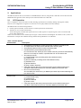
• Specifies the SH7264 MCU as the master device, and EEPROM as the slave device to write data to EEPROM
• Specifies the SH7264 MCU as the master device, and EEPROM as the slave device to read data from EEPROM
• The transfer rate is set to 391 kHz
• Uses interrupts for transmit end and receive data full
Note: Set the transfer rate to satisfy the EEPROM specifications.
1.2
Modules Used
• I C Bus Interface (IIC3)
• Interrupt Controller (INTC)
2
1.3
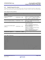
Applicable Conditions
MCU
Operating Frequency
Integrated Development
Environment
C Compiler
Compiler Options
1.4
SH7262/SH7264
Internal clock: 144 MHz
Bus clock: 72 MHz
Peripheral clock: 36 MHz
Renesas Electronics Corporation
High-performance Embedded Workshop Ver.4.07.00
Renesas Electronics SuperH RISC engine Family
C/C++ compiler package Ver.9.03 Release 00
Default setting in the High-performance Embedded Workshop
(-cpu=sh2afpu -fpu=single -debug -gbr=auto -global_volatile=0
-opt_range=all -infinite_loop=0 -del_vacant_loop=0 -struct_alloc=1)
Related Application Notes
For more information, refer to the following application notes:
• SH7262/SH7264 Group Example of Initialization
• SH7262/SH7264 Group I2C Bus Interface 3 Reception in Single-Master Mode (Read from EEPROM)
• SH7262/SH7264 Group I2C Bus Interface 3 Transmission in Single-Master Mode (Write in EEPROM)
1.5
About Active-low Pins (Signals)
The symbol "#" suffixed to the pin (or signal) names indicates that the pins (or signals) are active-low.
1.6
Hardware Conditions
This application may be run on the RSK+ for the SH7264 if an IIC EEPROM is added. This may be done by adding a
header at J12 and a small PCB with the EEPROM. Refer to RSK+SH7264 User Manual, REG10J0171 for details.
Please see section 2.3 of this App note for the specific EEPROM part number.
R01AN0068EJ0101 Rev. 1.01
Feb.10, 2012
Page 2 of 38