1
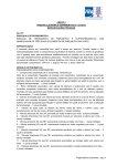
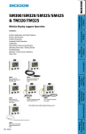
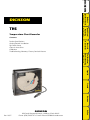
DICKSON
Product
Specifications &
Applications
DICKSON
Temperature Chart Recorder
Quick Start/
Operating
Instructions
TH6
Contents:
Charts &
Accessories
Product Specifications
Getting Started / Installation
Dip Switch Setup
Charts & Accessories
Calibration
Troubleshooting, Warranty / Factory Service & Returns
Calibrations/
Troubleshooting
& Warranty
Spanish
French
German
Rev. 10/07
Italian
DICKSON
930 South Westwood Avenue • Addison, Illinois 60101
Phone: (630) 543-3747 • E-mail: [email protected]
User Selectable Temperature TH621/22: 0 to ±50°F/C, 32 to +100°F; TH623/25: 0 to ±50°F/C,
Ranges (user selectable)
0 to ±100°F, 0 to +185°F, 0 to +85°C
Digital Temperature/RH Sensor
Ambient Operating
Conditions
+32 to +122°F (0 to +50°C), 0 to 95% RH (non-condensing); Probe
Only: -4 to +158°F (-20 to +70°C), 0 to 95% RH (non-condensing)
Power Source
120V 50/60Hz AC Adapter
Power Status Indicator
LED Indicator
Power Cord
6’ (2 meters)
Battery Backup
9V battery backup powers unit for up to 3 days
Chart Size (Diameter)
6”
Battery Life (Avg)
72 hours (Backup Only)
Recording Times
24-Hour 7-Day
Response Time
2.5 minutes
Alarm (TH623/25)
Audio/Visual on High/Low Temp/RH Limits
Relay Type
SPST, 24VDC, 0.5A, NO/NC - Relay does not function while unit is on
battery power.
Relay Connection
Spade Lugs, Male 0.25” - One Relay per Channel
Resolution
0.1 from -9.9 to 199.9; 1 above 2000 and below -9.9
Keypad Functions
On/Off, pen home, alarm
Display Type (TH622/23/25)
LCD, 3.5 digit, 3.3V
Display Dimensions
(TH622/23/25)
.59” x 1.18” (15mm x 30mm)
Dimensions (Inches/cm)
7.56 x 7.56 x 3.2519.2 x 19.2 x 8.3
Remote Probe Dimensions
(TH622/23/25)
Houses thermistor and RH sensor in polycarbonate plastic; 1.5” x 0.5”
(1.25cm x 4.5cm); Cable Length: 10 ft. (304cm)
Weight
2.16 lbs 979.7g
IP Rating
IP21
Warm-up Time
Less than 15 seconds
Units of Measure
F or C; RH
Storage Conditions
+32 to +122°F (0 to +50°C), 0 to 95% RH (non-condensing)
Enclosure
Rugged Black ABS Case, Polycarbonate Door, Aluminum Dial
Warranty
12 Month Limited
Included Accessories
AC Adapter, 1 Red and 1 Blue Pen, Probe, Manual and 9V Battery
(CHARTS SOLD SEPARATELY)
Italian
Rev. 10/07
German
Humidity Sensor
French
±2% from 10 to 60%, ±3% from 60 to 95%
Spanish
0 to 95% RH
Humidity Accuracy
Calibrations/
Troubleshooting
& Warranty
Humidity Range
Charts &
Accessories
Digital Temperature/RH Sensor
Quick Start/
Operating
Instructions
±0.5% of full scale, ±1.8°F (±1°C)
Temperature Sensor
Product
Specifications &
Applications
Temperature Accuracy
DICKSON
Product Specifications
3.
Insert a 9V battery and plug in AC adapter. Unit will power on. (see figure 3)
4.
The instrument will move pens to the appropriate readings.
5.
Install the chart that matches the Dip Switch settings you have selected.
a. Press the PEN HOME key to move the pens to the outside of the chart. The pen are automatically raised off the chart.
b. Remove the old chart, place the new chart on the Chart Hub – being certain that the edge of the chart slides under the Chart Guide Clips located at the outside of the chart.
6.
Set the appropriate time. There are two ways to adjust the chart and set the appropriate time:
a. Set the chart time manually by inserting a coin into the groove in the chart hub and turning
clockwise until the correct hour (and day if applicable) on the chart is referenced to the timing arrow (just to the right of the pen tip on the dial).
b. (This feature should be used for fine adjustments only) To adjust the chart time, press and hold ADJUST-UP and ADJUST-DOWN buttons located on the back of the unit next to the dip switch
(see figure 3). The green LED will blink rapidly for about five seconds, then the LED will remain
solid green. While in this state ADJUST-UP button will move the chart backward (counter clockwise) and ADJUST-DOWN button will move the chart forward (clockwise). Rotate the chart until the correct hour (and day if applicable) on the chart is referenced to the timing arrow. Once you have set your chart, press the PEN HOME button to exit Chart Adjust Mode. The unit will take one minute to exit Chart Adjust Mode once PEN HOME is pressed.
7.
Press PEN HOME to move the pens back onto the chart.
8.
Place the TH6 recorder on a flat vibration-free surface. Be sure it is in a vertical position and level.
For best performance and longevity, the location should be a clean environment, free from dust and
corrosive fumes. Do not exceed temperature specifications.
Wall Mount: Keyhole slots are provided on the TH6 recorder for wall mounting.
Calibrations/
Troubleshooting
& Warranty
Remove the protective pen caps.
Charts &
Accessories
2.
Quick Start/
Operating
Instructions
Your recorder has been preset to operate using the most popular settings.
Recording Time: 7 day
Range: TH621/22: +32 to +100°F; TH623/25: 0 to +100°F
To change the range and recording time, please reference Dip Switch Set-Up in this manual.
Product
Specifications &
Applications
1.
DICKSON
Quick Start
Display Symbols (TH622/623/25)
Spanish
FC
French
MAX
MIN
Figure 1
Button Operations
German
0N/OFF
The On/Off key turns the unit on and off.
PEN HOME
Rev. 10/07
Continued on next page
Italian
If the pen is located on the outside edge of the chart, press the PEN HOME to move pen to recording
position. If the pen is located on the chart, press the PEN HOME key to move the pen to the outside edge of
the chart.
TH621/22
PEN
HOME
ALARM
PEN
HOME
(PWR) LED
ON/ OFF
ON/ OFF
If the pen(s) are located on the outside edge of the chart, press the PEN HOME to move pen(s) to recording
position. If the pen(s) are located on the chart, press the PEN HOME key to move the pen(s) to the outside
edge of the chart.
ALARM – (TH623/25)
Pressing either the ADJUST-UP or ADJUST-DOWN buttons, located on the back of the unit next to the dip switch, will toggle the alarm on or off.
3.
Pressing PEN HOME will scroll to the next alarm option. The options are as follows:
a. alarm on or off
b. pen 1 alarm min
c. pen 1 alarm max
d. pen 2 alarm min
e. pen alarm max
4.
In order to set pen alarm minimums and maximums, pressing ADJUST-UP will increase the alarm value,
and pressing ADJUST-DOWN will decrease the alarm value. There is acceleration if the ADJUST-UP
button is held down. Repetitively pressing the PEN HOME button will scroll through the five options
until the alarm button is pressed to exit from alarm adjust. Each press of the PEN HOME or ALARM
button will store the new settings. The unit will take one minute to exit Alarm Set Mode once the
ALARM button is pressed.
5.
If the alarm is triggered, the LED will show as solid red and the alarm will sound. Press the ALARM
button to silence Audible Alarm.
French
Figure 3
Adjust Buttons
Spanish
2.
Calibrations/
Troubleshooting
& Warranty
To set the alarm, make sure unit is on and press and hold the ALARM button. The LED will blink red
rapidly for about five seconds, then the LED will turn solid green. Release the ALARM button and the
LED will turn solid red. At this point the display will show the following: ON or OFF.
Charts &
Accessories
1.
Quick Start/
Operating
Instructions
PEN HOME
Product
Specifications &
Applications
(PWR)
LED
DICKSON
Figure 2
TH623/25
Relay Contacts
Remote Probe
(TH623/625)
German
Battery
Compartment
Rev. 10/07
Italian
AC
Adapter
Jack
Continued on next page
The SPST 24V 500mA relay contacts are normally open and will close on alarm conditions when the alarms
are enabled. Relay contacts are always functional when the alarm is enabled. The relay will close only
during minimum and maximum alarm conditions.
Dip Switches for ranges
2
3
4
5
6
7
8
Slide toggle down for off position.
For Model
7 Day
All Models
D
2
U
3
4
D
D
All Models
TH623/25
+32 to +100°F
TH621/22
0 to 100
D
D
0 to +185°F
TH623/25
0 to 200
D
U
0 to +50°C
All Models
U
D
0 to +85°C
TH623/25
U
U
Remember to install the correct chart for your range
Dickson - Addison, Il www.dicksondata.com
0 to +100°F
(TH623/25)
#3 down
#4 down
+32 to +100°F
(TH621/22)
#3 down
#4 down
0 to +185°F
(TH623/25)
#3 down
#4 up
0 to +50°C
(TH621/22/23/25)
#3 up
#4 down
0 to +85°C
(TH623/25)
Recording Time
#3 up
#4 up
Calibrations/
Troubleshooting
& Warranty
24 Hour
0 to +100°F
The TH6 will record up to 4 temperature ranges
(depended on model). Dip switch #3 & #4 allow
you to select the temperature range.
Charts &
Accessories
Switches 2-4
0 to 100
1
Temperature Range
DICKSON TH6 Dip Switch Settings:
#25201
Up = On; Down = Off
Chart
Slide toggle up for on position.
Dip Switch 1,
7 & 8 are not
active on this
recorder.
Quick Start/
Operating
Instructions
To set-up the TH6 recorder for your specific
application, you might need to change some of the
Dip Switches. The Dip Switches are located on the
back of the unit (figure 3). Use a pen or small screw
driver to flip the switches. Remember to install
correct chart to match corresponding
Product
Specifications &
Applications
Dip Switch Set-Up
DICKSON
Alarm Relays (TH625)
The TH6 recorder has two different recording time
options
7 day
#2 up
#2 down
Spanish
24 hour
NOTE: Remember to install correct chart to match
corresponding switch setting.
French
German
Italian
Rev. 10/07
(for current pricing go to www.dicksondata.com or call 1-800-323-2448)
Accessories
24 hour Charts
C664
C658
C658
C667
7 day Charts
C663
C657
C657
C665
(for current pricing go to www.dicksondata.com or call 1-800-323-2448)
Description
NIST Traceable Calibration 3-pt. (new unit)
Order Number
N300
N100
A2LA Accredited Calibration 3-pt. (new unit)
N400
Pens (3 red/3 blue)
P246
Universal International AC Adapter
R065
Your instrument was carefully tested and calibrated before being shipped from the factory. For greatest accuracy, we recommend factory re-calibration every 6-12 months. Call customer service at (630) 543-3747. If
you wish to do calibration yourself, follow these procedures.
To activate calibration mode, turn the unit on and press and hold both the On/Off button and the AdjustUp button (making sure to press the Adjust-Up button first so the unit will not turn off). The led will blink in amber rapidly for about five seconds, and turn solid green. Release the On/Off button and the
Adjust-Up button, the led will then blink amber at which point only the pen being adjusted will show on the display.
2. To raise the unit of measurement, press the Adjust-Down button. To lower the unit of measurement, press the Adjust-Up button. Pen home switches between the red and blue pens on a two pen unit and
stores the current adjustment value.
4.
Note: After two hours, if no buttons are pressed, the unit will time out of user calibration and resume
normal operation. The user calibration is stored separately from the factory calibration. If you wish to cancel out your user calibration, simply enter calibration mode and toggle through the steps without
adjusting displayed readings. Exit by pressing the On/Off button. You have now restored factory calibration.
French
Note: It is recommended that you use a controlled chamber when calibrating temperature and humidity.
Calibrating in an open room is not recommended as humidity can vary greatly within a very small area.
Spanish
3. When calibration is complete, press the On/Off button. Calibration is stored in memory even after you turn the unit off. User calibration information will not be lost if AC power fails.
Calibrations/
Troubleshooting
& Warranty
1.
Charts &
Accessories
Calibration
Quick Start/
Operating
Instructions
NIST Traceable Calibration 1-pt. (new unit)
Product
Specifications &
Applications
Temperature Range
0 to +50˚C
+32 to +100˚F
0 to ±100˚F/ 0 to +85˚C
0 to +185˚F
DICKSON
Charts
German
Italian
Rev. 10/07
Continued on next page
N100 - NIST Traceable Calibration 1-Point: Includes documentation to one Dickson pre-selected point
on new units only.
N400 - Deluxe A2LA Accredited NIST Traceable Calibration 3-Point: ISO Guide 25/A2LA
Documentation of 3 pre-selected points of as found data before and after calibration for Dickson
temperature and/or humidity instrumentation on new units only.
N995 - NIST User Selected Temperature Points: Documentation of one customer specified point.
Should be selected in addition to one of the above calibration options.
Once you begin to use your precision Dickson instrumentation, regular calibrations are necessary to ensure
accurate readings.
The following Calibration Services are available:
N350 - NIST Traceable Calibration 3-Point: Includes documentation of three Dickson pre-selected
points (a high, medium, and low) after re-calibration.
N995 - NIST User Selected Temperature Points: Documentation of one customer specified point.
Should be selected in addition to one of the above calibration options.
Why should I recalibrate my instrumentation?
Over time dirt, dust and normal handling can throw your precision instrumentation out of calibration.
Regular calibrations ensure that you receive the most accurate readings possible.
Our Capabilities
Dickson is the first manufacturer of humidity and temperature instrumentation to receive A2LA
accreditation. We are also NIST Traceable; our procedures conform to MIS-STD-45662A, ANSI/NCSL 25401-1994, ISO/IEC Guide 25 and ISO10012. We are experts in the manufacture and calibration of humidity and
temperature instruments. Easy: We make it easy for you! No phone calls for Return Authorization Numbers are required. We remind you when your instrument is due for calibration. You simply send in the completed Calibration
Order Form with your unit for calibration with freight prepaid to Dickson.
German
Fast Service: Our turnaround time is 3 days or less so you receive not only expert service but fast service as well.
French
Why should I return my instrument to Dickson for calibration?
Dickson calibrates your instrument at the factory using proprietary production/calibration software that
guarantees proper calibration.
Spanish
How often should I recalibrate my instrumentation?
Depending on the environment your instrument is used in and how often it is handled you will want to
recalibrate your instrument every 6 to 12 months. Instruments in environments where there are extreme
temperatures, wide temperature ranges, humidity or pressure variations, high condensation, dirt, dust and
other debris will require calibration at least every 6 months. Instruments that are frequently moved or in
locations with heavy machinery that cause vibrations should also be calibrated at least every 6 months.
Calibrations/
Troubleshooting
& Warranty
N450 - Deluxe A2LA Accredited NIST Traceable Calibration 3-Point: ISO Guide 25/A2LA
Documentation of 3 pre-selected points of as found data before and after calibration for Dickson
temperature and/or humidity instrumentation.
Charts &
Accessories
N150 - NIST Traceable Calibration 1-Point: Includes documentation to one Dickson pre-selected point
after re-calibration.
Quick Start/
Operating
Instructions
The Importance and Benefits of Regular Calibrations
Product
Specifications &
Applications
N300 - NIST Traceable Calibration 3-Point: Includes documentation of three Dickson pre-selected
points (a high, medium, and low) on new units only.
DICKSON
Calibration Services - New Units
Italian
Rev. 10/07
Continued on next page
For troubleshooting information, click here for the technical support page.
Warranty
Contact the factory (630-543-3747) for a Return Authorization (RA) Number before returning any
instrument. The model number, serial number and a purchase order number will be requested before an RA
number is issued.
Customer Satisfaction
Dickson takes pride in providing you, the customer, with the highest quality instrumentation. We welcome
the opportunity to help you in any way possible. Whether it be a question or a new idea in documentation,
the Dickson Company would like to hear your response. Please call our Customer Service Department at
1-800-323-2448 or (630) 543-3747 (in Illinois).
Spanish
Software Return Policy
IMPORTANT-Read your Software License Agreement carefully before installing software. DIckson will accept
returns for replacement of defective disks and CDs only.
Calibrations/
Troubleshooting
& Warranty
NOTE: Dickson shall not be liable for consequential or incidental damages resulting from failure or
malfunction of its products.
Charts &
Accessories
• Carefully repack the instrument, label the outside of the box with the RA# and return the instrument (freight pre-paid) to Dickson.
• All instruments that do not have the RA# clearly marked on the outside of the box will be refused. When returning instruments for credit, please include all accessories in shipment.
• Calibration/Freight charges are non-refundable.
Quick Start/
Operating
Instructions
Factory Service & Returns
Product
Specifications &
Applications
Dickson warrants that the products it sells will be free from defects in material and workmanship under
normal use and service for a period of twelve months after delivery. In the event of a claim under this
warranty, the product or part must be returned to the factory for repair or replacement (shipping pre-paid)
with a Return Authorization Number (see Return Information above). It will be repaired at Dickson’s option
without charge. This warranty DOES NOT cover routine calibration, pen, chart and battery replacement. The
foregoing warranty and remedy are exclusive and in lieu of all other warranties either expressed or implied.
Dickson shall not be liable for consequential or incidental damages resulting from failure or malfunction of
its products. Dickson makes no warranty for products not manufactured by it or for any products modified by
buyer, or subject to misuse or neglect.
DICKSON
Troubleshooting
French
German
Italian
Rev. 10/07
Registrador de temperatura y de humedad
Arranque rápido
El instrumento mueve los estiletes hacia las lecturas apropiadas
5.
Instale el gráfico que coincida con los ajustes del interruptor Dip que ha seleccionado.
a. Pulse la tecla PEN HOME para mover el estilete hacia la extremidad del gráfico. El estilete se eleva automáticamente sobre el gráfico.
b. Quite el gráfico usado y coloque uno nuevo en el Concentrador de Gráficos – comprobando que el borde del gráfico se deslice por debajo de las Presillas de Guía de Gráficos situadas en la extremidad del gráfico.
6.
Establezca el tiempo adecuado. Hay dos maneras de ajustar el gráfico y establecer el tiempo
adecuado:
a. Establezca el tiempo manualmente insertando una moneda en la ranura del concentrador de gráficos y girándola en el sentido de las agujas del reloj hasta que la hora correcta (y el día, si
corresponde) en el gráfico haga referencia a la flecha temporizadora (exactamente a la derecha de la punta del estilete en el cuadrante).
b. (Esta característica sólo debe utilizarse para ajustes finos) Para ajustar el tiempo del gráfico,
pulse y mantenga apretados los botones ADJUST-UP y ADJUST-DOWN situados en la parte
posterior de la unidad junto al interruptor Dip (vea la figure 3). El LED verde parpadea
rápidamente alrededor de cinco segundos y luego pasa a ser de color verde entero. En este estado, el botón ADJUST-UP mueve el gráfico hacia delante (en el sentido de las agujas del reloj)
y el botón ADJUST-DOWN lo hace hacia atrás (en sentido contrario al de las agujas del reloj). Gire el gráfico hasta que la hora correcta (y el día, si corresponde) en el gráfico haga referencia a
la flecha temporizadora. Una vez ajustado el gráfico, pulse el botón PEN HOME para salir del Modo de Ajuste de Gráfico. La unidad tarda un minuto para salir del Modo de Ajuste de Gráfico cuando se pulsa PEN HOME.
7.
Pulse el botón PEN HOME para retornar los estiletes al gráfico.
8.
Coloque el registrador TH6 en una superficie plana libre de vibraciones. Compruebe que esté en
posición vertical y nivelado. Para rendimiento máximo y larga vida útil, la unidad requiere un entorno
limpio, libre de polvo y humos corrosivos. No se debe exceder las especificaciones de temperatura.
Visualización de símbolos (TH622/23/25)
French
Montaje en pared: En el registrador TH6 se suministran ranuras de chaveta para montaje en pared.
Spanish
Inserte pila de 9V y conecte el adaptador de CA. (Vea la figura 3)
4.
Calibrations/
Troubleshooting
& Warranty
Quite las tapas protectoras de los estiletes.
3.
Charts &
Accessories
2.
Quick Start/
Operating
Instructions
El registrador ha sido preajustado para operar con los parámetros de mayor aceptación.
Tiempo de registro: 7 día
Rango:TH621/22: +32 a +100°F; TH623/25: 0 a +100°F
Para cambiar el rango y el tiempo de registro, consulte la referencia en este manual sobre la instalación
de interruptores Dip.
Product
Specifications &
Applications
1.
DICKSON
DICKSON TH621/622/623/625
Figura 1
Rev. 10/07
Italian
MAX
MIN
German
FC
TH621/22
PEN
HOME
(PWR)
LED
PEN HOME
PEN
HOME
Conexión /
desconexión
ON/ OFF
ALARMA
ON/ OFF
Conexión /
desconexión
Product
Specifications &
Applications
(PWR) LED
ALARM
DICKSON
Figura 2
TH623/25 PEN HOME
Operaciones con botones
PEN HOME
Si el(los) estilete(s) están colocados en el borde exterior del gráfico, pulse PEN HOME para colocarlo(s) en
posición de grabación. Si el(los) estilete(s) está(n) colocados en el gráfico, pulse la tecla PEN HOME para
moverlo(s) hacia el borde exterior del gráfico.
Al pulsar los botones ADJUST-UP o ADJUST-DOWN, situados en la parte posterior de la unidad junto al interruptor Dip, la alarma alterna entre conexión o desconexión.
3.
Al pulsar PEN HOME, se desplaza hacia la siguiente opción de alarma. Las opciones son las siguientes:
a. Alarma conectada o desconectada
b. Estilete 1 alarma mínima
c. Estilete 1 alarma máxima
4.
Con el objeto de ajustar las alarmas mínimas y máximas de los estiletes, pulse ADJUST-UP para aumentar el valor de la alarma y ADJUST-DOWN para disminuir su valor. Se produce aceleración si se mantiene apretado el botón ADJUST-UP. Pulse repetidamente el botón PEN HOME para que se desplace a través de las cinco opciones hasta que se pulse el botón de alarma para salir de ajuste de alarma. Cada pulsación del botón PEN HOME o ALARM permite el almacenamiento de los nuevos parámetros. La unidad requiere un minuto para salir del modo de ajuste de alarma una vez que se
pulse el botón ALARM.
5.
Si se activa la alarma, el LED aparece de color rojo entero y la alarma emite un sonido. Pulse el botón ALARM para silenciar una alarma audible.
Relés con alarma
(TH625)
Battery
Compartment
AC
Adapter
Jack
Italian
Rev. 10/07
Relay Contacts
Remote Probe
(TH623/625)
German
Los contactos del relé SPST 24V 500mA
están normalmente abiertos y se cierran
en condiciones de alarma cuando éstas se
activan. Los contactos del relé son siempre
funcionales cuando se activa la alarma. El
relé sólo se cierra durante condiciones de
alarma mínimas y máximas.
Figure 3
Adjust Buttons
French
2.
Spanish
Para ajustar la alarma, compruebe que la unidad esté conectada y pulse y mantenga apretado el botón
ALARM. El LED parpadea rápidamente en rojo alrededor de cinco segundos, y luego pasa a ser de color verde entero. Libere el botón ALARM Y el LED se apaga. En este momento, la visualización
muestra lo siguiente: ON o bien OFF.
Calibrations/
Troubleshooting
& Warranty
1.
Charts &
Accessories
ALARMA – (TH623/25)
Quick Start/
Operating
Instructions
CONEXIÓN/DESCONEXIÓN
La tecla de conexión/desconexión activa y desactiva la unidad.
Interruptores Dip para gamas
Switches 2-4
For Model
7 Day
All Models
Chart
D
2
U
3
4
D
D
All Models
TH623/25
+32 to +100°F
TH621/22
0 to 100
D
D
0 to +185°F
TH623/25
0 to 200
D
U
0 to +50°C
All Models
U
D
0 to +85°C
TH623/25
U
U
0 to 100
Remember to install the correct chart for your range
Dickson - Addison, Il www.dicksondata.com
El registrador TH8 tiene dos opciones diferentes de
tiempo de grabación.
24 Hora
#2 Arriba
7 Día
#2 Abajo
3
4
5
6
7
8
Conmutación deslizante hacia abajo para posición de desconexión.
Rangos de Temperatura
El TH6 Puede registrar hasta 4 rangos de
temperatura (según el modelo). Los interruptores
basculantes #3 y #4 le permitirán seleccionar el
rango de temperaturas.
0 to +100°F
(TH623/25)
#3 Abajo
#4 Abajo
+32 to +100°F
(TH621/22)
#3 Abajo
#4 Abajo
0 to +185°F
(TH623/25)
#3 Abajo
#4 Arriba
0 to +50°C
(KT621/22/23/25)
#3 Arriba
#4 Abajo
0 to +85°C
(TH623/25)
#3 Arriba
#4 Arriba
Spanish
Nota: Recuerde que el gráfico que instale para
que sea correcto debe coincidir con los parámetros
de los interruptores Dip.
Calibrations/
Troubleshooting
& Warranty
Tiempo de grabación
2
Charts &
Accessories
24 Hour
0 to +100°F
1
Quick Start/
Operating
Instructions
DICKSON TH6 Dip Switch Settings:
#25201
Up = On; Down = Off
Conmutación deslizante hacia arriba para posición de conexión.
Product
Specifications &
Applications
Para configurar el registrador TH6 en su aplicación
concreta, sería necesario cambiar algunos de los
interruptores Dip. Los interruptores Dip están situados
en la parte posterior de la unidad (figura 3). Utilice
una lapicera o destornillador pequeño para soltar los
interruptores. Recuerde que el gráfico que instale
para que sea correcto debe coincidir con los
parámetros de los interruptores Dip.
DICKSON
Instalación de interruptor Dip
La garantía Dickson
French
Dickson garantiza que la línea de instrumentos TH6 no presentará defectos de material y de mano de obra
en el uso y servicio normales durante un periodo de doce meses posteriores a la entrega.
Esta garantía no cubre calibración de rutina, estiletes, gráficos y reemplazo de batería.
Para Asistencia Técnica entre en la dirección Web: www.dicksondata.com
German
Italian
Rev. 10/07
Enregistreur de température et d’humidité
Débuter
4.
L’instrument déplacera les stylos selon les lectures appropriées.
5.
Installez le graphe correspondant aux paramètres de commutateur Dip sélectionné.
a. Pressez la touche PEN HOME pour déplacer le stylo hors du graphe. Le stylo est
automatiquement retiré hors du graphe.
b. Retirez l’ancien graphe, placez le nouveau graphe sur le connecteur de graphe en vous assurant
que le bord du graphe glisse sous les clips de guidage de graphe situés en dehors du graphe.
6.
Fixez l’heure appropriée. Il existe deux méthodes pour ajuster le graphe et fixer l’heure appropriée:
a. Fixez manuellement l’heure du graphe en insérant une pièce dans la fente du connecteur de
graphe et en tournant dans le sens des aiguilles d’une montre jusqu’à arriver à l’heure correcte
(et le jour, si cela est applicable) sur la flèche de durée sur le graphe (juste à droite du bout du stylo sur le composeur).
b. (Cette fonction ne devrait être utilisée que pour l’affinage de l’ajustage) Pour ajuster l’heure du graphe, pressez et maintenez enfoncés les boutons ADJUST-UP et ADJUST-DOWN situés à
l’arrière de l’unité près du commutateur Dip (Veuillez consulter la figure 3). La diode LED verte
clignotera rapidement pendant près de cinq secondes puis restera au vert. Dans cet état, le bouton ADJUST-UP fera avancer le graphe (dans le sens des aiguilles d’une montre) et le bouton ADJUST-DOWN le fera reculer (dans le sens contraire de celui des aiguilles d’une
montre). Faites tourner le graphe jusqu’à arriver à l’heure correcte (et le jour, si cela est applicable) sur la flèche de durée sur le graphe. Une fois que vous avez configuré votre graphe, pressez le bouton PEN HOME pour sortir du mode d’ajustage de graphe (Chart Adjust). L’unité
prendra une minute pour sortir du mode d’ajustage de graphe une fois que PEN HOME est pressé.
7.
Pressez PEN HOME pour déplacer les stylos sur le graphe.
8.
Placez l’enregistreur TH6 sur une surface plane sans vibrations. Assurez-vous d’une position verticale
et d’une mise à niveau. Pour une meilleure performance et longévité, l’emplacement devrait être dans
le cadre d’un environnement propre, sans poussières ou vapeurs corrosives. Ne dépassez pas les
spécifications de température.
Affichage de symboles (TH622/23/25)
French
Pose murale: Des fentes sont réservées à la pose murale de l’enregistreur TH6.
Spanish
Insérez une pile 9V/AA et branchez l’adaptateur AC. (Veuillez consulter la figure 3)
Calibrations/
Troubleshooting
& Warranty
Retirez les bouchons protecteurs des stylos.
3.
Charts &
Accessories
2.
Quick Start/
Operating
Instructions
Votre enregistreur a été configuré pour fonctionner avec les paramètres les plus courants. Durée d’enregistrement: 7 jour(s)
Portée: TH621/22: +32 à +100°F; TH623/25: 0 à +100°F
Veuillez vous référer au chapitre Configuration de commutateur Dip de ce manuel pour changer les paramètres de durée d’enregistrement et de portée.
Product
Specifications &
Applications
1.
DICKSON
DICKSON TH621/622/623/625
Figure 1
German
FC
MAX
MIN
Italian
Rev. 10/07
TH621/22
PEN HOME
(PWR)
LED
ALARME
PEN HOME
PEN
HOME
(PWR)
LED
ON/ OFF
PEN
HOME
ON/ OFF
ON/OFF
ON/OFF
ON/OFF
La touche On/Off active ou désactive l’unité.
ALARM - (TH623/25)
Une pression sur un des boutons ADJUST-UP ou ADJUST-DOWN situés à l’arrière de l’unité près du commutateur Dip activera ou désactivera l’alarme.
3.
Une pression sur PEN HOME fera défiler vers l’option suivante de l’alarme. Les options sont comme
suit:
a. alarme activée ou désactivée
b. alarme min. Stylo 1
c. alarme max. Stylo 1
4.
Pour ajuster les valeurs d’alarme minimum et maximum du stylo, pressez ADJUST-UP pour augmenter la valeur d’alarme et ADJUST-DOWN pour la diminuer. Il y aura une accélération si le bouton ADJUST-UP est maintenu enfoncé. Une pression répétée de PEN HOME fera défiler les cinq options jusqu’à ce que soit pressé le bouton d’alarme our quitter l’ajustage d’alarme. Chaque pression
sur PEN HOME ou sur ALARM permettra le stockage des nouvelles valeurs. Il prendra à l’unité une
minute pour quitter le mode ALARM SET une fois pressé le bouton ALARM.
5.
Si l’alarme est déclenchée, la diode LED indiquera une couleur rouge solide et une alarme sera
entendue. Pressez le bouton ALARM pour mettre au silence l’alarme sonore.
Relais d’alarme
(TH625)
Relay Contacts
Remote Probe
(TH623/625)
Battery
Compartment
German
Les contacts de relais SPST 24V 500mA
sont normalement ouverts et seront fermés
lorsque les conditions d’alarmes seront
activées. Les contacts de relais sont
toujours fonctionnels lorsque l’alarme est
activée. Le commutateur Dip N° 8 n’a
aucun effet sur le relais. Le relais ne se
fermera que lors de conditions minimales et
Figure 3
Adjust Buttons
French
2.
Spanish
Pour fixer une alarme, assurez-vous que l’unité est activée puis pressez et maintenez enfoncé le bouton ALARM. La diode LED rouge clignotera rapidement pendant près de cinq secondes puis passera au
vert solide. Relâchez le bouton ALARM et la diode LED s’éteindra. A ce point, l’affichage indiquera les
détails suivants: ON ou OFF.
Calibrations/
Troubleshooting
& Warranty
1.
Charts &
Accessories
PEN HOME
Si le ou les stylos sont situés sur le bord extérieur du graphe, pressez PEN HOME pour les déplacer en
position d’enregistrement. Si le ou les stylos sont situés sur le graphe, pressez PEN HOME pour les déplacer
vers le bord extérieur du graphe.
Quick Start/
Operating
Instructions
Opérations des boutons
Product
Specifications &
Applications
ALARM
DICKSON
Figure 2
TH623/25
maximales d’alarmes.
Italian
Rev. 10/07
AC
Adapter
Jack
Pour configurer l’enregistreur TH6 pour votre application spécifique, vous pourriez avoir à changer certains
réglages des commutateurs Dip. Les commutateurs Dip sont situés à l’arrière de l’unité (Veuillez consulter la
figure 3). Utilisez un stylo ou un petit tournevis pour modifier les réglages des commutateurs. Souvenezvous d’installer le graphe correct correspondant au réglage du commutateur Dip.
DICKSON TH6 Dip Switch Settings:
#25201
Up = On; Down = Off
For Model
7 Day
All Models
Chart
D
2
U
3
4
D
D
D
24 Hour
All Models
0 to +100°F
TH623/25
+32 to +100°F
TH621/22
0 to 100
D
0 to +185°F
TH623/25
0 to 200
D
U
0 to +50°C
All Models
U
D
0 to +85°C
TH623/25
U
U
0 to 100
Heure d’enregistrement
L’enregistreur TH8 dispose de deux options
différentes de durée d’enregistrement
7 Jour
+32 to +100°F
(TH621/22)
#3 Bas
#4 Bas
0 to +185°F
(TH623/25)
#3 Bas
#4 Haut
0 to +50°C
(TH621/22/23/25)
#3 Haut
#4 Bas
0 to +85°C
(TH623/25)
#3 Haut
#4 Haut
#2 Haut
#2 Bas
NOTE: Souvenez-vous d’installer le graphe correct
correspondant au réglage du commutateur Dip.
Calibrations/
Troubleshooting
& Warranty
24 Heure
#3 Bas
#4 Bas
Charts &
Accessories
Remember to install the correct chart for your range
Dickson - Addison, Il www.dicksondata.com
0 to +100°F
(TH623/25)
Quick Start/
Operating
Instructions
Switches 2-4
L’appareil TH6 enregistrera jusqu’à cinq portées de
température (selon le modèle). Le commutateur
Dip N°3 et N°4 vous permettent de sélectionner la
portée de température.
Product
Specifications &
Applications
Portée de température
Commutateurs Dip pour les portées
DICKSON
Configuration du commutateur Dip
Spanish
La garantie Dickson
Cette garantie ne couvre pas l’étalonnage de routine, le stylo, le graphe et le remplacement de piles.
French
Dickson garantit que la ligne TH6 d’instruments sera sans défauts en matériel et en fabrication sous un
usage normal et sera sous service pour une période de douze mois après la livraison.
Visitez le site www.dicksondata.com pour l’assistance technique.
German
Italian
Rev. 10/07
DICKSON
DICKSON TH621/622/623/625
Gerät zur Aufzeichnung von Temperatur und Feuchtigkeit
Schnellstart
5.
Installieren Sie das Diagramm, das mit den von Ihnen gewählten Einstellungen des Abblendschalters übereinstimmt.
a. Betätigen Sie die STIFT HOME Taste, um den Stab zur Außenseite des Diagramms zu bewegen. Der Stab wird selbständig vom Diagramm weg nach oben bewegt.
b. Entfernen Sie das alte Diagramm, legen sie das neue Diagramm auf die Diagrammscheibe vergewissern Sie sich, dass die Kante der Diagrammfolien sich unter den Leitklemmen des Diagramms auf der Diagrammaußenseite befindet.
6.
Stellen Sie die richtige Zeit ein. Es gibt zwei Verfahren, um das Diagramm anzupassen und eine
angemessene Zeit einzustellen:
a. Stellen Sie die Zeit von Hand ein, indem Sie eine Münze in die Rille der Diagrammdrehscheibe einführen und diese im Uhrzeigersinn bis zur richtigen Stunde drehen (und Tag, wenn sich dies als der Fall erweisen sollte); auf dem Diagramm auf den Timing-Pfeil (unmittelbar rechts neben der Spitze des Schreiberspitze der Wählerscheibe.
b. (Dieses Feature sollte nur zur Feineinstellung verwendet werden) Um die Diagrammzeit
einzustellen, passen Sie die Diagrammzeit an, drücken und halten Sie die neben dem
Abblendschalter (siehe Abbildung 3) auf der Rückseite der Geräteeinheit befindlichen ADJUST-UP und ADJUST-DOWN gedrückt. Die grüne LED blinkt in schneller Folge etwas fünfmal
auf, danach verbleibt die LED in einem satten Grün In diesem Zustand bewegt der ADJUST-UP
Button das Diagramm weiter (im Uhrzeigersinn) und der ADJUST-DOWN Button bewegt das Diagramm rückwärts weiter (entgegen dem Uhrzeigersinn). Rotieren Sie das Diagramm solange weiter, bis auf dem Diagramm der Zeitzeiger auf die korrekte Stunde (und Tag, falls angebracht) zeigt. Nachdem Sie das Diagramm eingestellt haben, drücken Sie den STIFT HOME Button, um den Diagramm-Einrichtungsmodus zu verlassen. Nach Drücken des STIFT HOME Buttons dauert es eine Minute
bis zum Verlassen des Diagramm-Einrichtungsmodus.
7.
Drücken Sie STIFT HOME, um den Stift auf das Diagramm zurück zu bewegen.
8.
Stellen Sie das TH6 Aufzeichnungsgerät auf eine flache, vibrationsfreie Oberfläche Vergewissern
Sie sich, dass es sich in einer senkrechten Position und Lage befindet. Eine saubere, staubfreie
Umgebung frei von Korrosionsdämpfen sind die Voraussetzung für optimale Leistung und Lebensdauer.
Überschreiten Sie nicht die Temperaturvorschriften.
Symboloptionen anzeigen
(TH622/23/25)
German
Wandhalterung: Schlüsselloch-Schlitze werden auf dem TH6 Aufzeichnungsgerät zwecks Wandbefestigung
zur Verfügung gestellt.
French
Das Instrument bewegt die Stäbe auf die ordnungsgemäßen Ablesewerte.
Spanish
9V/AA-Batterie einfügen und in Wechselstromadapter stecken (siehe Abbildung 3)
4.
Calibrations/
Troubleshooting
& Warranty
Entfernen Sie die Schutzkappen des Stifts.
3.
Charts &
Accessories
2.
Quick Start/
Operating
Instructions
Ihr Aufzeichnungsgerät wurde voreingestellt, um esunter den meist verwendeten Einstellungen zu betreiben.
Aufzeichnungszeit: 7 Tag
Bereich: TH621/22: +32 bis +100°F; TH623/25: 0 bis +100°F
Um Bereich und Aufzeichnungszeit zu ändern, lesen Sie bitte in diesem Leitfaden unter
Abblendschalter Einstellungen weiter.
Product
Specifications &
Applications
1.
FC
Abbildung 1
Rev. 10/07
Italian
MAX
MIN
TH621/22
STIFT HOME
(PWR)
LED
ON/ OFF
ALARM
PEN
HOME
Product
Specifications &
Applications
ALARM
PEN
HOME
DICKSON
Abbildung 2
STIFT HOME
TH623/25
(PWR)
LED
ON/ OFF
EIN/AUS
EIN/AUS
Knopfbedienungen
STIFT HOME
Falls der/(die) Stift(e) sich auf dem Außenrand des Diagramms befinden, drücken Sie STIFT HOME, um
den/(die) Stift(e) in die Aufzeichnungsstellung zu bewegen. Falls sich der/(die) Stift(e) auf dem Diagramm
befindet, drücken Sie die STIFT HOME Taste, um den/(die) Stift(e) auf den Außenrand des Diagramms zu
bewegen.
Um den Alarm einzustellen, vergewissern Sie sich, dass die Geräteeinheit eingeschaltet ist. Dann
drücken Sie den ALARM Button und halten diesen danach weiterhin gedrückt. Die LED blinkt in
schneller Folge etwa fünfmal auf, danach verbleibt die LED in einem satten Grün. Nach Loslassen des
ALARM Buttons erlischt die LED. In diesem Zustand zeigt die Anzeige folgendes an: EIN (ON) oder AUS
(OFF).
2.
Durch Drücken der ADJUST-UP oder ADJUST-DOWN Knöpfe, die sich auf der Rückseite der
Geräteeinheit neben dem Abblendschalter befinden, ermöglicht das Ein- und Ausschalten des Alarms.
3.
Durch Drücken von STIFT HOME bewegt man sich in der Anzeige zur nächsten Bildoption. Folgende Optionen sind gegeben:
a. Alarm ein oder aus
b. Stift 1 Alarm min
c. Stift 1 Alarm max
4.
Zum Einrichten der Mindest- und Höchsteinstellungen des Alarms für den Stift wird durch Drücken von ADJUST-UP der Alarmwert erhöht und durch Drücken von ADJUST-DOWN der Alarmwert erniedrigt.
Durch Gedrückthalten des ADJUST-UP Buttons wird dieser Einstellvorgang beschleunigt. Wiederholtes
Drücken des STIFT HOME Knopfes bewegt die Anzeige durch fünf Optionen, bis der Alarmknopf
gedrückt wird, um die Alarmanpassung zu verlassen. Jedes Drücken des STIFT HOME oder ALARM
Knopfes speichert die neuen Einstellungen. Die Geräteeinheit benötigt eine Minute zum Verlassen des
Alarmeinstellmodus, nachdem der ALARM Knopf gedrückt wurde.
5.
Falls der Alarm ausgelöst wurde, die LED leuchtet in rot und der Alarm erklingt. Drücken Sie den
ALARM Knopf, um den hörbaren Alarm stumm zu schalten.
French
Alarmrelais (TH625)
Relay Contacts
Remote Probe
(TH623/625)
Battery
Compartment
German
Die SPST 24V 500mA Relaiskontakte sind
normalerweise geöffnet und schließen sich,
wenn Alarmbedingungen gegeben sind
und Alarm aktiviert ist. Bei aktiviertem
Alarm funktionieren die Relaiskontakte
immer. Abblendschalter Nr. 8 beeinflusst
das Relais nicht. Das Relais schließt
sich nur bei maximalen und minimalen
Figure 3
Adjust Buttons
Calibrations/
Troubleshooting
& Warranty
1.
Spanish
Charts &
Accessories
ALARM – (TH623/25)
Quick Start/
Operating
Instructions
EIN/AUS (ON/OFF)
Die Ein/Aus- (On/Off) Taste schaltet die Geräteeinheit an oder aus.
Alarmbedingungen.
Italian
Rev. 10/07
AC
Adapter
Jack
Abblendschalterbereiche
DICKSON TH6 Dip Switch Settings:
#25201
Up = On; Down = Off
For Model
7 Day
All Models
Chart
D
2
U
3
4
D
D
24 Hour
All Models
0 to +100°F
TH623/25
+32 to +100°F
TH621/22
0 to 100
D
D
0 to +185°F
TH623/25
0 to 200
D
U
0 to +50°C
All Models
U
D
0 to +85°C
TH623/25
U
U
0 to 100
Aufzeichnungszeit
Das TH6 Aufzeichnungsgerät verfügt über zwei
verschiedene Optionen zur Aufzeichnungszeit
7 Tag
+32 to +100°F
(TH621/22)
#3 Nach unten
#4 Nach unten
0 to +185°F
(TH623/25)
#3 Nach unten
#4 Nach
0 to +50°C
(TH621/22/23/25)
#3 Nach
#4 Nach unten
0 to +185°C
(TH623/25)
#3 Nach
#4 Nach
#2 Nach
#2 Nach unten
Hinweis: Denken Sie daran, das korrekte
Diagramm zu installieren, die mit der
entsprechenden Abblendschaltereinstellung
übereinstimmen muss.
Calibrations/
Troubleshooting
& Warranty
24 Stunde
#3 Nach unten
#4 Nach unten
Charts &
Accessories
Remember to install the correct chart for your range
Dickson - Addison, Il www.dicksondata.com
0 to +100°F
(TH623/25)
Quick Start/
Operating
Instructions
Switches 2-4
Temperaturbereich
Der TH6 zeichnet bis zu fünf Temperaturbereiche
auf (in Abhängigkeit vom Modell). Abblendschalter
Nr. 3 und Nr. 4 ermöglichen ihnen die Auswahl des
Temperaturbereichs.
Product
Specifications &
Applications
Zum Einstellen des TH6 Aufzeichnungsgeräts für Ihre spezifischen Anwendungen könnte es erforderlich
sein, dass Sie die Abblendschalter ändern. Die Abblendschalter befinden sich auf der Rückseite der
Geräteeinheit (Abbildung 3). Verwenden Sie einen kleinen Schraubenzieher, um die Schalter umzustellen.
Denken Sie daran, das korrekte Diagramm zu installieren, die mit der entsprechenden
Abblendschaltereinstellung übereinstimmen muss.
DICKSON
Einstellen des Abblendschalters
Spanish
Die Dickson Gewährleistung
Routinemäßige Kalibrierung und das Ersetzen von Stift, Diagramm und Batterie sind in dieser
Gewährleistung nicht enthalten.
French
Dickson gewährleistet, dass die TH6 Produktlinie von Instrumenten für die Dauer von 12 Monate nach
Auslieferung und bei normaler Nutzung frei von Material- und Verarbeitungsmängeln ist.
Für technischen Support verweisen wir Sie auf www.dicksondata.com
German
Italian
Rev. 10/07
Registratore di temperature ed umidità
Avvio veloce
4.
Lo strumento sposterà i pennini sulle letture idonee.
5.
Installare il diagramma che corrisponde alle impostazioni selezionate per l’interruttore Dip.
a. Premere il tasto PEN HOME per spostare il pennino all’esterno del diagramma. Il pennino viene automaticamente sollevato dal diagramma.
b. Estrarre il vecchio diagramma, inserirne uno nuovo sul perno del diagramma – assicurandosi che il bordo del diagramma scivoli sotto i fermagli di guida del diagramma che si trovano al di fuori dello stesso.
6.
Impostare l’ora idonea. Ci sono due modi per regolare il diagramma ed impostare l’ora idonea:
a. Impostare manualmente l’ora del diagramma inserendo una moneta nella scanalatura del perno del diagramma e ruotando in senso orario finché l’ora corretta (ed il giorno se applicabile)
del diagramma corrisponde a quella indicata dalla freccia (subito a destra della punta del pennino sul quadrante).
b. (Questa funzione deve essere usata solo per regolazioni di precisione) Per regolare l’ora del
diagramma, premere e tenere premuti i pulsanti ADJUST-UP e ADJUST-DOWN che si trovano a tergo dell’unità vicino all’interruttore Dip (vedere figura 3). Il LED verde lampeggerà per circa cinque secondi, poi il LED resterà costantemente acceso. In queste condizioni il pulsante ADJUST
UP consentirà il movimento del diagramma in avanti (in senso orario) ed il pulsante ADJUST-
DOWN consentirà il movimento del diagramma all’indietro (in senso anti-orario). Ruotare il
diagramma finché l’ora corretta del diagramma (e giorno se applicabile) corrisponde all’ora indicata dalla freccia. Una volta impostato il diagramma, premere il pulsante PEN HOME
per uscire dalla modalità di Regolazione Diagramma. L’unità uscirà dalla modalità di Regolazione Diagramma entro un minuto se si preme il pulsante PEN HOME.
7.
Premere il tasto PEN HOME per portare il pennino di ritorno sul diagramma.
8.
Sistemare il TH6 registratore su una superficie piana priva di vibrazioni. Assicurarsi che sia in posizione perpendicolare ed a livello. Per migliori prestazioni e durata, l’ubicazione deve essere un ambiente
pulito, libero da polvere e fumi corrosivi. Non superare le temperature specificate.
Spanish
Inserire una batteria da 9V e collegare l’adattatore CA. (vedere figura 3)
Calibrations/
Troubleshooting
& Warranty
Togliere il cappuccino protettivo del pennino.
3.
Charts &
Accessories
2.
Quick Start/
Operating
Instructions
Il registratore è stato pre-impostato al funzionamento utilizzando le impostazioni più diffuse. Ora di registrazione: 7 giorno
Campo di misura: TH621/22: +32 a +100°F; TH623/25: 0 a +100°F
Per modificare il campo di misura e l’ora di registrazione consultare la sezione Impostazione
interruttore DIP di questo manuale.
Product
Specifications &
Applications
1.
DICKSON
DICKSON TH621/622/623/625
Installazione a parete: Sul registratore TH6 sono stati praticati fori sagomati per l’installazione a parete.
French
Simboli visualizzati (TH622/23/25)
Figura 1
German
FC
MAX
MIN
Italian
Rev. 10/07
TH621/22
PEN HOME
(PWR)
LED
STIFT HOME
PEN
HOME
(PWR)
LED
ON/ OFF
ALLARME
PEN
HOME
Product
Specifications &
Applications
ALARM
DICKSON
Figura 2
TH623/25
ON/ OFF
ON/OFF
EIN/AUS
ON/OFF
Il tasto On/Off serve ad accendere e spegnerà l’unità.
ALLARME - (TH623/25)
Premendo il pulsante ADJUST-UP o quello ADJUST-DOWN, che si trovano a tergo dell’unità vicino all’interruttore Dip, si attiva o disattiva l’allarme.
3.
Premendo PEN HOME si passa all’opzione d’allarme successiva. Le possibilità sono:
a. allarme attivato o disattivato
b. pennino 1 allarme di minima
c. pennino 1 allarme di massima
4.
Per impostare i valori minimi o massimi d’allarme per un pennino, premendo ADJUST-UP si aumenta il valore dell’allarme e premendo ADJUST-DOWN si diminuisce il valore dell’allarme. Si accelera se il
pulsante ADJUST-UP è tenuto premuto. Premendo ripetutamente il pulsante PEN HOME si scorrono le
5 possibilità fino a quando il pulsante d’allarme viene premuto per uscire dalla regolazione dell’allarme.
Ciascuna pressione del pulsante PEN HOME o di quello ALARM INSERIRÀ IN MEMORIA LE NUOVE
IMPOSTAZIONI. L’unità uscirà dalla modalità di Regolazione Diagramma entro un minuto se si preme il
pulsante ALARM.
5.
Se viene azionato l’allarme, il LED sarà acceso a luce rossa stabile e si udrà l’allarme. Premere il
pulsante ALARM per interrompere l’allarme sonoro.
Relè d’allarme (TH625)
condizioni minime e massime d’allarme.
Relay Contacts
Remote Probe
(TH623/625)
Battery
Compartment
AC
Adapter
Jack
Italian
Rev. 10/07
Figure 3
Adjust Buttons
German
I contatti del relè SPST 24V 500 mA sono
normalmente aperti e si chiuderanno in
condizioni d’allarme quando gli allarmi
sono attivabili. I contatti del relè sono
sempre operativi quando l’allarme è
attivabile. L’interruttore Dip #8 non
influisce sul relè. Il relè si chiude solo nelle
French
2.
Spanish
Per impostare l’allarme, assicurarsi che l’unità sia accesa e premere e tenere premuto il pulsante
ALARM. Il LED rosso lampeggerà rapidamente per circa cinque secondi, poi il LED resterà
costantemente a luce verde. Rilasciando il pulsante ALARM il LED si spegne. A questo punto il display
visualizzerà quanto segue: ON oppure OFF.
Calibrations/
Troubleshooting
& Warranty
1.
Charts &
Accessories
ORIGINE PENNINO
Se i pennini si trovano al di là del bordo del diagramma, premere il tasto PEN HOME per riportare il pennino
alla posizione di registrazione. Se i pennini si trovano sul diagramma, premere il tasto PEN HOME per
portare i pennini sul bordo esterno del diagramma.
Quick Start/
Operating
Instructions
Funzionamento dei pulsanti
Per impostare il registratore TH6 per un’applicazione specifica, può essere necessario cambiare alcuni degli
interruttori Dip. Gli interruttori Dip si trovano a tergo dell’unità (figura 3). Per agire sugli interruttori usare
una penna o un piccolo cacciavite. Assicurarsi di installare il diagramma corrispondente alle
impostazioni degli interruttori Dip.
Campo temperatura
DICKSON TH6 Dip Switch Settings:
#25201
Up = On; Down = Off
For Model
7 Day
All Models
Chart
D
2
U
3
4
D
D
24 Hour
All Models
0 to +100°F
TH623/25
+32 to +100°F
TH621/22
0 to 100
D
D
0 to +185°F
TH623/25
0 to 200
D
U
0 to +50°C
All Models
U
D
0 to +85°C
TH623/25
U
U
0 to 100
#3 Giù
#4 Giù
+32 to +100°F
(TH621/22)
#3 Giù
#4 Giù
0 to +185°F
(TH623/25)
#3 Giù
#4 Su
0 to +50°C
(TH621/22/23/25)
#3 Su
#4 Giù
0 to +85°C
(TH623/25)
Ora di registrazione
24 Ora
7 Giorno
#2 Su
#2 Giù
Nota Bene: Assicurarsi di installare il diagramma
corrispondente alle impostazioni degli interruttori
Dip.
Spanish
La garanzia Dickson
Calibrations/
Troubleshooting
& Warranty
Il registratore TH8 possiede tre possibilità diverse
per l’ora di registrazione
#3 Su
#4 Su
Charts &
Accessories
Remember to install the correct chart for your range
Dickson - Addison, Il www.dicksondata.com
0 to +100°F
(TH623/25)
Quick Start/
Operating
Instructions
Switches 2-4
Il TH6 registrerà fino a 4 campi di temperatura
(a seconda del modello). Gli interruttori Dip #3,
#4 e #5 consentono di selezionare il campo di
temperatura.
Product
Specifications &
Applications
Interruttori Dip per i campi di misura
DICKSON
Impostazione dell’interruttore Dip
Dickson garantisce che la linea di strumenti TH6 sarà priva di difetti di materiale e manodopera nelle
condizioni normali d’uso e di servizio per il periodo di dodici mesi dalla consegna.
French
Questa garanzia non copre la Calibrazione di routine, il pennino, il diagramma e la sostituzione della
batteria.
Per l’assistenza tecnica accedere al sito www.dicksondata.com
German
Italian
Rev. 10/07