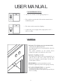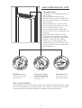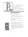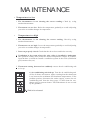
1
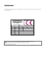
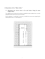
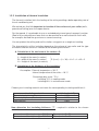
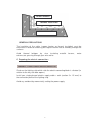
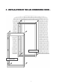
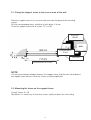
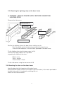
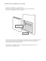
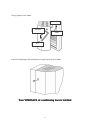
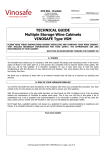
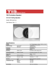
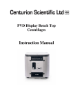
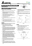
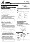
AIR – CONDITIONING DOOR
VSE-PC1-VSE-PC2
ASSEMBLING MANUAL
&
USER MANUAL
! !"
#$
% & ' (( )"* ( !+ ,- . (
/ ' (( )"* ( !+ ,- .+ ,(
01 & 23 4 2
21
SAFETY INSTRUCTIONS
•
•
•
5
66&
0 2 972 8
%5 66&
1
2
1
1 7 2
66&
5
&95 9= > * 1
66&
11
)
96& 2
%5
&
2
•
•
5 :
1 9 )16 = &
22
7: 5 ? 2
5 66&
5
&
72
2
5 1
66&
7
5 66&
*
66&
216& 8 5
2
2 * 1
2&
7 :
2 2 6
5 54 2 :
9 2 5
@
5
•
2&
7 2 5 6 62
2 85 5
16
: 8
!;
- ;<
:
2 725 6 62
5 1 7:
62 :& 5 66&
2
6 26 &
7
5
96&
5 42& 9 2 72 1
66&
7 2
2
62
%5
9
:7
1 9 = 6&9 5
5 1
82 @ ) 5
9
&7
2
:&
25
9 528 2
%5 66&
1 7 2: &
&
&
7
2 2
2
4
5
&
&5 5 :
71
@
= 5
7 2 := 5
21
8 9
&
& 2 52 & : 5 @ :7 A &
&
%5
1
5&
& 2 : 5 & 62 :& 2 5 2 A
5 66&
2
5 2 5
5
&72
2
&
7 2
2
7
2
2 2
/
2 &
# 2
2 &
•
#2 2 &
&
28 72 9 5&
2 6&78 5 5 66&
@7 8 5 5
5 %5 7 2 & &
2@ 51 &
4
•
#2 2 &
•
5 66&
21 5 1
9) 6&9 5 66&
2 26
&A
6&9 5
1
•
=
7 9& 2
2 :7 A &
2 2
&
76
•
•
9=
9 2
2 5 22 85
&
&
7
66&
)
& 8 572
2 2
82 @
#2 2 & 4 5
26
25
2
2
11
&
72
2
96& 2 5 66&
*
@
5 66&
6&9 5 66&
6
B 65 1
66&
785&
@ 91
5
: @ *
5
:& %5
66&
2
9
=): 2@ 8 :2 & = > *=
5 1
66&
7
2
5
:& 85 5 7
2&
29
@ 5 66&
2
66 24
!
"
%5 2&
&
28 9
2
2 9
2 6&
52 & : 6&
C
:5
5 26 9 &
&2 5
VINOSAFE
PAUL MULLER S.A.
2 rue des Artisans
F 68280 SUNDHOFFEN
Type :
N° de serie :
VSB :
Volts :
AVR :
Watts :
ATB :
R134a :
PCVS :
Année :
Hz :
gr
CL :
TVR :
72
5
5 12 &=76
2 5
2 6&
#$
21 2 2 5 &
& 1: 85 5
528
(
= &8 7
SUMMARY
1.1. Measuring the reserve area in the wall before fixing the door
support frame
1.2. Insulating work in the wine cellar
1.2.1. Installation of a vapour barrier
1.2.2. Installation of thermal insulation
2.1. Fixing the support frame to the reserve area of the wall
2.2. Mounting the frame on the support frame
2.3. Mounting the lighting strip on the door frame
2.4. Mounting the door on the door frame
2.5. Mount the air-conditioner on to the door
.
1.1. Measuring the reserve area in the wall before fixing the door
support frame
The support frame, the base for the whole air-conditioner door and door frame, must be
completely fitted into the wall of your wine cellar.
For this purpose, it is advisable, if necessary, to build the reserve area respecting the
following dimensions as shown opposite :
S
T
A
N
D
A
R
T
2
0
3
0
S
P
E
C
I
A
L
%
&
'
&
(
1.2. Insulating work in the wine cellar
Your room must satisfy precise insulating criteria so that your VINOSAFE airconditioning door can effectively and durably regulate the ambient air while minimising
your electric consumption.
IMPORTANT
The insulating work must be carried out on all the surfaces of the wine cellar (walls,
grounds, celling) according to the following procedure
1.21. Installation of a vapour barrier :
%5 8
62
4 62
21 9
5 2 95 5
21 2
5 && )22& * %5 /
4
2 2 51 7
9 4 &5 1 & &
22 2 9 2 &: &
5
0 2
6 26
2 D
2 2 5
97
%2 42 5 =
)8 &&= && 9=9 2
:
0 2
2
2 7 5 &&
9 5 & 95 2
2 2 22& 5
2 A 6 && 5
*
2
2 5
7 24
9 5 8 &&8 5 62&75
7 24
95
8 5
&1
1 E: 1
7 24
95
8 5
&1
1 E62&75
25
&
& 2
54
7 66&7 9: 1
&& )8 1 * 2
6 92 8 =
2 @ 8 5 @2 1 & 8
# 1 9 92 5 5 1 &
%5
5
5
76 6&
&1
2162
2162
&&
= &&
1.2.2. Installation of thermal insulation
The thermal insulation limits the heating of the cellar providing a better operating rate of
the air-conditioning unit.
We remind you that it is important to insulate all the surfaces of your cellar (walls,
ground and celling) over the vapour barrier.
For the ground, it is preferable to use an extruded polystrene type of compact insulator
(Roof mat) or polyurethane foam that can be covered for a more attractive finish with,
for example, washed fine gravel over a cement covering.
You can protect the celling and wall insulation using paint or a rough cast coating.
The characteristics of the insulation depend on the volume of your cellar and the type
of material chosen and are in relation to the following calculations :
A. Calculation of the total area of the surfaces S :
L = length of the room (in metres)
W = width of the room (in metres)
H = Height of the room (in metres)
S (in m²) = (L + W) x H x 2 + L x W x 2
B. Calculation of the thickness of the insulation :
Assumption : External temperature = 30° C
Internal temperature of the cellar = 10° C
Percentage duty cycle : 75 %
including 15 % in cooling mode
including 60 % in maintenance mode
Choose your insulating material and retain the corresponding insulating coefficient λ :
λ (In kcal/m/° C)
0.038
0.026
0.022
Insulating material
Expanded polystrene
Extruded polystrene (Roof mat)
Polyurethane
Now determine the insulating thickness “T” : required in relation to the chosen
material.
For an air conditioning door type PCVS 1
For an air conditioning door type PCVS 2
,
T (mm) = λ x S x 70
T (mm) = λ x S x 33
VAPOUR BARRIER
THERMAL INSULATION
WALL
GENERAL PRECAUTIONS
The insulation of the cellar (vapour barrier an thermal insulation) must be
continuous in order to avoid any passage of harmful heat or humidity through the
surfaces.
Avoid thermal bridges by also insulating
columns,etc.,passing through your wine cellar.
metallic
beams,
water
C. Preparing the electric connection :
WARNING : Power supply must be switch off
Check on the lighting strip which side the electric connecting block is situated (in
relation to the way the door opens).
Install your single-phased electric supply cable + earth (section 3 x 1.5 mm²) to
the connection point of the lighting strip.
Avoid any accident by momentarily cutting the power supply.
!
! " ##" ! $
$ % !&
" '
$
( $
SUPPORT FRAME
DOOR FRAME
+
) ($ $ '
2.1. Fixing the support frame to the reserve area of the wall
Place the support frame in the reserve area and mark the place of the mounting
screws.
Drill the corresponding holes and drive in the 6 plugs ∅ 8 mm.
Fix on the support frame with 6 screws T.F. 6 x 50.
SUPPORT
FRAME
WALL
SCREWS WITH
PLUG
OUTSIDE
HORIZONTAL SECTION
NOTE
You can place wooden wedges between the support frame and the walls not to deform
the support frame columns while the screws are being tightened.
2.2. Mounting the frame on the support frame
Using 6 screws 5 x 25.
Sometimes it is necessary to force the screws slightly to obtain the self-cutting.
-"
2.3. Mounting the lighting strip on the door frame
WARNING : UNPLUG POWER SUPPLY BEFORE CONNECTING
LIGHTING STRIP.
Remove the side covers
YELLOW INDICATOR CAP
GREEN INDICATOR CAP
INDICATORS
SIDE COVERS
LIGHTING STRIP
Position the lighting strip on the door frame, making sure to :
* Pass the white switch into the hole provided in the door frame,
* Place the two indicators in the two holes provided in the door frame,
Fix the lighting strip using the two screws (4x16).
Connect the supply cable to the strip block
respecting the colour of the wires :
* Black = Live
* Blue = Neutral
* Green/Yellow = Earth
Fix the side covers using the two screws 4x10
2.4. Mounting the door on the door frame
Hook the door into the hinge pins of the door frame.
Slide the black flexible sheath (at the upper angle of the door) in the notch provided on
the light strip and fix it into place by screwing the nut.
Mount the two red connectors.
--
2.5. Mount the air-conditioner on to the door
Place the air-conditioner in front of the door.
Mount the two connectors (bottom of the door and air-conditioning unit)
Install the air-conditioning unit on the slide rail.
CONNECTORS
SLIDE RAIL
Move the hooks using the hexagonal key in the side holes of the air-conditioning unit so
that the hooks slide into the slits provided on the door and provisionally grip the
anchorage points without tightening them.
Check that the air-conditioning unit is no rubbing against the door frame. If it is,
reposition the air-conditioning unit.
-
Firmly tighten each hook.
HOOK
HOOK
SIDE HOLE
ANCHORAGE
POINT
HEXAGONAL
KEY
Insert the two plugs which block the handle holes of the hooks.
*
$ "%
-(
USER MA NUAL
", , -- "
•
.
5 82 8 5 2 5 &95 9
• %5 8
5
2 9
2
• %5 2 5
5
5 628
5* 2 6&9
* ./
•
•
•
66&
7 :& ) 9& 65
•
($
)
<5 @ 5 5 &95 926
%5 &95 52 &
2
22
&
2
%5 7 &&
28
2 2
85 5 5 &95 2
&$ *
%5 &95 9
&2:
8 5 2 7
5 8
&
2 = 2 / 16& 2
5 &95 8 5 2-
!- "
5 @5 5
5 @5 5
22 82@
-.
" '
.
+ , ,# + 2
21 &
&95
•
5 2 2& 5
8 5 2 2& 5 &95 9
• <2
•
2 5 8
6 2"
21
&
&
7 85
5 2
5 8
5
528
&
&
2 1
&
&
7 72
&
& 8 5 5 22
@ :2 &
5
=
5 8 5: @ 2" 2
6 4 8
9 92
+"#* , - ) 2662
&95 8 5
2"=
85 8 56 5 26
9
&
7
*
:7 5
!+ "
"
.0
,
+! 0+
2 5
2
2 9)8 5
2
6*
%5 9
&95 52 & 21 2
%5
& 26
2
2 &
7
%5 /
& 26
2&
785 5
22& 9
%5
5 12
6
21 0
2
16
2 :2 2-(;<
5 8
&&
%5 16
: C
:0
8
!;<
- ;< :7
95 20
2&@ 2:
5 16
2
5 &
&
26 22 &
28=) 8
= 2 / 16&*
5
@ 5 5 16
5 &
& 8&
& &
&
= 5
8 5 5
2
2 9
8 &&
21
&&
7 @ 24 21 5
90
2 7 1 2
21
5
& 16
%
,
)#2 2 2
5 62 2 *
9
6
)
6
-
)
211
: 8
-(;<*
10
, 3
9
)#2 2 2
6 5 62 2 *
+ *! 1 /0,
2
5 5 1 7 22&
28 5 2@ 8 && 72 )& @ 9 *= 5 5 1 7
5 2@
&: & 1 79212 &7 : 5 8 8 &
&2:
%5
2 9
5 :
6 &
&
7
9
21
26 1 1 5 1 7
-
22595
2 0
* +
.
4 ! + +", "0 -
1 && 12 2
2
2 &
7 8
2/79
5
%5
6
24
%5
& 1
:
&
&
&
2
22
.
+!* +
+
•
8
21 5 2
25 &
& 2
4
:2 &
5 9
9&&
7
5
6& 8 5
6&
!0
)
" $
C 5 16
9
&
&
7 4 7 1 &&
1
25 5
2
2 9
2 2
26
2
/
4&
7&
2 9 1 )2 42
9
6*
)
$
•
4 2:
5 4
& 2 9&
&
5 22 2 24
5
•
%5 && 52 & : 6&
8 &
&
04 &
85
5 16
2 2 /
( ;<=2
5 5
9 2
8&
&:
4
•
#
@
:7 5
2
2 9
1 7
5
72 26
2 %5
2
2 9
52 & : 5 @
9&&
72
5 5
2
& %5
2
2 9
52 & :
&
2 5 22 )6 9 --*
5 2
52 &
: &
9 4
1 &
%5 1
2 24
:7 5 9
.
Side to be cleaned
-
MA INTENANCE
•
)
-
$ <5 @ :7
25
72 8
•
9
5 121
2
5 16
16
5 9
9
&&
7 2 42
:C
9
)
-
<5 @ :7
9
2 5 5 121
28
72 8
2
(
5 16
16
5 9
) )
. 1
)5 62:&1
&
&
7
26 5 22 2 8 28
9 &&
=/
2
= *
<5 @ 5
85
9
&&
7 2 42
:C
&
2@ 2
&
7
5 22 &
2
5
595*
62 :&=
5 221 )4 & 2
5 2
16
&
& 4 & 2 7 1
5
2
9
2
2
9
6
6 !
)$ %
5
2
2 9
2 2 .! 52
2 9 =
9 5 5 5 12
: 8
5 1 1 1
1 /1 1 16
5
6 2:&1 6
=
2
5 1
66&
7= 124 5
2
2 9
21 5 22 )6 9 --*
&
5 20
9 4
1 &
%5 1
2 24
:7 5 9
Side to be cleaned
-,
(Receipt to join at the order)
I, the undersigned, Mr
_____________________________________________________________
Residing at
_____________________________________________________________
_____________________________________________________________
Declare that I have received the installation and recommandations guide for
the VINOSAFE air-conditioning door VSE-PC1 / VSE-PC2.
Signed at __________________________ on ____________________
CUSTOMER’S SIGNATURE
-!