1
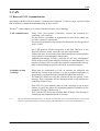
EtherCAN-S7
EtherCAN/2-S7
Industrial Ethernet / UDP Gateway
Software Manual
to Product C.2050.07, C.2051.07
EtherCAN-S7
Software Manual • Doc. No.: C.2050.28 / Rev. 1.2
esd electronic system design gmbh
Vahrenwalder Str. 207 • 30165 Hannover • Germany
www.esd.eu • Fax: 0511/37 29 8-68
Phone: 0511/37 29 80 • International: +49-5 11-37 29 80
Page 1 of 48
NOTE
The information in this document has been carefully checked and is believed to be entirely reliable. esd
makes no warranty of any kind with regard to the material in this document, and assumes no
responsibility for any errors that may appear in this document. esd reserves the right to make changes
without notice to this, or any of its products, to improve reliability, performance or design.
esd assumes no responsibility for the use of any circuitry other than circuitry which is part of a product
of esd gmbh.
esd does not convey to the purchaser of the product described herein any license under the patent rights
of esd gmbh nor the rights of others.
esd electronic system design gmbh
Vahrenwalder Str. 207
30165 Hannover
Germany
Phone:
Fax:
E-mail:
Internet:
+49-511-372 98-0
+49-511-372 98-68
[email protected]
www.esd.eu
USA / Canada:
esd electronics Inc.
525 Bernardston Road
Suite 1
Greenfield, MA 01301
USA
Phone:
Fax:
E-mail:
Internet:
Page 2 of 48
+1-800-732-8006
+1-800-732-8093
[email protected]
www.esd-electronics.us
Software Manual • Doc. No.: C.2050.28 / Rev. 1.2
EtherCAN-S7
Document file:
I:\Texte\Doku\MANUALS\CAN\EtherCAN\Englisch\EtherCAN-S7\EtherCAN_to-S7_Software_en_12.wpd
Date of print:
2009-09-21
Software version:
EtherCAN 0.1
Changes in the chapters
The changes in the user’s manual listed below affect changes in the software as well as changes in the
description of the facts only.
Chapter
Changes versus previous version
-
First version
-
-
Technical details are subject to change without notice.
EtherCAN-S7
Software Manual • Doc. No.: C.2050.28 / Rev. 1.2
Page 3 of 48
This page has been left blank intentionally.
Page 4 of 48
Software Manual • Doc. No.: C.2050.28 / Rev. 1.2
EtherCAN-S7
Contents
1. Introduction . . . . . . . . . . . . . . . . . . . . . . . . . . . . . . . . . . . . . . . . . . . . . . . . . . . . . . . . . . . . . . . . . 7
2. Configuration Procedure . . . . . . . . . . . . . . . . . . . . . . . . . . . . . . . . . . . . . . . . . . . . . . . . . . . . . . . 8
2.1 Configure CP-Hardware . . . . . . . . . . . . . . . . . . . . . . . . . . . . . . . . . . . . . . . . . . . . . . . . . . . . . 8
2.2 Configuration of Network with NetPro . . . . . . . . . . . . . . . . . . . . . . . . . . . . . . . . . . . . . . . . . 10
2.2.1 Accessing NetPro Program . . . . . . . . . . . . . . . . . . . . . . . . . . . . . . . . . . . . . . . . . . . . 10
2.2.2 NetPro Program Window . . . . . . . . . . . . . . . . . . . . . . . . . . . . . . . . . . . . . . . . . . . . . 11
2.2.3 Adding a Station . . . . . . . . . . . . . . . . . . . . . . . . . . . . . . . . . . . . . . . . . . . . . . . . . . . . 12
2.2.4 Configuration Other Station . . . . . . . . . . . . . . . . . . . . . . . . . . . . . . . . . . . . . . . . . . . 12
2.3 Configuring the Connection . . . . . . . . . . . . . . . . . . . . . . . . . . . . . . . . . . . . . . . . . . . . . . . . . 14
2.4 Copying Components from Included Project . . . . . . . . . . . . . . . . . . . . . . . . . . . . . . . . . . . . 16
3. CAN . . . . . . . . . . . . . . . . . . . . . . . . . . . . . . . . . . . . . . . . . . . . . . . . . . . . . . . . . . . . . . . . . . . . . . . 17
3.1 Basics of CAN Communication . . . . . . . . . . . . . . . . . . . . . . . . . . . . . . . . . . . . . . . . . . . . . . 17
3.2 CAN Errors and CAN Error Localization . . . . . . . . . . . . . . . . . . . . . . . . . . . . . . . . . . . . . . . 31
4. Functional Characteristics . . . . . . . . . . . . . . . . . . . . . . . . . . . . . . . . . . . . . . . . . . . . . . . . . . . .
4.1 Function Block FB77 . . . . . . . . . . . . . . . . . . . . . . . . . . . . . . . . . . . . . . . . . . . . . . . . . . . . . . .
4.1.1 Parameters CONN_ID and MOD_ADDR . . . . . . . . . . . . . . . . . . . . . . . . . . . . . . . .
4.1.2 Configuring the CAN Bit Rate with BAUD . . . . . . . . . . . . . . . . . . . . . . . . . . . . . . .
4.2 Data Type UDT1 . . . . . . . . . . . . . . . . . . . . . . . . . . . . . . . . . . . . . . . . . . . . . . . . . . . . . . . . . .
4.2.1 UDT1 with CAN Messages (CMSG) . . . . . . . . . . . . . . . . . . . . . . . . . . . . . . . . . . . .
4.2.2 UDT1 in CAN Events (EVMSG) . . . . . . . . . . . . . . . . . . . . . . . . . . . . . . . . . . . . . . .
4.3 Data Module DB1 . . . . . . . . . . . . . . . . . . . . . . . . . . . . . . . . . . . . . . . . . . . . . . . . . . . . . . . . .
4.4 Data Block DB2 . . . . . . . . . . . . . . . . . . . . . . . . . . . . . . . . . . . . . . . . . . . . . . . . . . . . . . . . . . .
4.4.1 CanIdRange . . . . . . . . . . . . . . . . . . . . . . . . . . . . . . . . . . . . . . . . . . . . . . . . . . . . . . . .
32
32
34
35
37
37
40
43
44
44
5. Monitoring Ethernet Communication via Heartbeat . . . . . . . . . . . . . . . . . . . . . . . . . . . . . . . 45
6. Appendix . . . . . . . . . . . . . . . . . . . . . . . . . . . . . . . . . . . . . . . . . . . . . . . . . . . . . . . . . . . . . . . . . . . 46
6.1 Bit-Timing Values (Examples) . . . . . . . . . . . . . . . . . . . . . . . . . . . . . . . . . . . . . . . . . . . . . . . 46
6.2 S7-Returned Values . . . . . . . . . . . . . . . . . . . . . . . . . . . . . . . . . . . . . . . . . . . . . . . . . . . . . . . . 47
EtherCAN-S7
Software Manual • Doc. No.: C.2050.28 / Rev. 1.2
Page 5 of 48
This page has been left blank intentionally.
Page 6 of 48
Software Manual • Doc. No.: C.2050.28 / Rev. 1.2
EtherCAN-S7
Introduction
1. Introduction
This manual describes the functionality of EtherCAN-S7 (C.2050.07) and the EtherCAN/2-S7
(C.2051.07). In this manual both modules are described together as EtherCAN-S7.
EtherCAN-S7 connects the Siemens-PLC S7 with the CAN bus via a FB77 function block.
PC with
SIMATIC Manager
and NetPro
S7
with FB77Function Block
Configuration
ELLSI
Control
Ethernet
Data
ELLSIInterface
EtherCAN-S7
CAN-Interface
Control
CAN Bus
Data
CAN
Fig. 1: Connection of Siemens-PLC S7 to a CAN bus via EtherCAN-S7
By means of function block FB77 and EtherCAN-S7 a Siemens-PLC-S7 with industrial Ethernet
interface can transmit and receive CAN telegrams and monitor the status of the connected CAN bus.
The network is configured via the Siemens tool NetPro.
EtherCAN-S7 communicates with Siemens-PLC S7 via ELLSI protocol by esd. Please refer to the
ELLSI software manual for further information about ELLSI. This application does not require
knowledge on ELLSI, however.
EtherCAN-S7
Software Manual • Doc. No.: C.2050.28 / Rev. 1.2
Page 7 of 48
Configuration
2. Configuration Procedure
First start the SIMATIC manager and create a new project. Insert a new station and start the hardware
manager. Insert a CP.
If your PLC already supports Industrial Ethernet, configure it accordingly (please refer to the manual
of your PLC).
Double-clicking CP opens the properties window for CP hardware configuration.
2.1 Configure CP-Hardware
- Properties of CP:
In order to configure the properties of
Ethernet-S7 click on the Properties
button.
The window shown in fig. 3 will open.
Fig. 2: CP properties
In the window Properties-Ethernet
interface you can now configure the IP
address of the CP and the subnetwork
mask.
Confirm your entries with OK.
Fig. 3: Parameters
Page 8 of 48
Software Manual • Doc. No.: C.2050.28 / Rev. 1.2
EtherCAN-S7
Configuration
In the SIMATIC manager the CP is now entered at slot 4.
Fig. 4: Entry of CP in SIMATIC manager
- Save hardware configuration
Saving the new hardware configuration.
EtherCAN-S7
Software Manual • Doc. No.: C.2050.28 / Rev. 1.2
Page 9 of 48
Configuration
2.2 Configuration of Network with NetPro
2.2.1 Accessing NetPro Program
Fig. 5: Accessing NetPro
By double-clicking the symbol for Ethernet(2), which is in the right-hand side of the window, you
access the program NetPro.
Page 10 of 48
Software Manual • Doc. No.: C.2050.28 / Rev. 1.2
EtherCAN-S7
Configuration
2.2.2 NetPro Program Window
The program window of the NetPro program is opened.
Fig. 6: NetPro program window
EtherCAN-S7
Software Manual • Doc. No.: C.2050.28 / Rev. 1.2
Page 11 of 48
Configuration
2.2.3 Adding a Station
Here you can now add „Other station“. Click the directory Stations in Selection of network objects
(right) in the tree structure. Now select Other station and drag this into the main window of the program
NetPro with the mouse (Drag-and-Drop). As shown in the figure below, the symbol for the Other
station is shown in the main window.
Fig. 7: Adding a station
2.2.4 Configuration Other Station
By double-clicking the icon Other station the input
window Properties-Other station shown on the left is
opened. Here you can configure interfaces.
Change to the tab Interfaces in the properties window
and select interface New.. to add a new interface.
Fig. 8: Properties Other station
Page 12 of 48
Software Manual • Doc. No.: C.2050.28 / Rev. 1.2
EtherCAN-S7
Configuration
Select Industrial Ethernet as type in selection window New
interface-Selection of type and confirm the selection with
OK.
Fig. 9: Selection of type
Now the following properties window for the configuration of the Ethernet interface opens.
Fig. 10:
Properties Ethernet interface
In this properties window for the Ethernet interface you select tab Parameters and can now enter the
IP address as well as the subnet mask of the EtherCAN-S7 module (please refer to the hardware manual
of the EtherCAN module, too).
Select the Ethernet that is also connected to the CP (here Ethernet (2)).
Confirm your entries with OK.
EtherCAN-S7
Software Manual • Doc. No.: C.2050.28 / Rev. 1.2
Page 13 of 48
Configuration
2.3 Configuring the Connection
- Industrial Ethernet:
Fig. 11: Connection window
When you select the symbol for the CPU of the SIMATIC300 in the main window, a connection
window opens in the lower part of the program window. Now right-click into the first row of the
connection window and select Insert new connection in the context menu that opens.
The window shown on the left opens.
In this window select Other station(1) as a connection
partner and UDP connection as a connection type. When
confirming with OK the properties window for the UDP
connection opens (fig. 13).
Fig. 12: New connection
Page 14 of 48
Software Manual • Doc. No.: C.2050.28 / Rev. 1.2
EtherCAN-S7
Configuration
- Properties of the UDP connection
Change to tab Addresses.
Fig. 13:
Properties UDP connection
In tab Addresses you must make sure to
enter Port 2209 in PORT (DEC) in both
fields, i.e. under Local as well as under
Remote.
Fig. 14: Addresses
- Save network configuration
Save the new network configuration.
EtherCAN-S7
Software Manual • Doc. No.: C.2050.28 / Rev. 1.2
Page 15 of 48
Configuration
2.4 Copying Components from Included Project
Copy the following components from the included project:
FB77, FC5, FC6, DB1, DB2, DB3, DB77, UDT1
Fig. 15: Components from included project
FB77
FC5,
FC6
is the function block for processing the ELLSI protocol.
are the Siemens functions AG_SEND and AG_RECV for the handling of UDP packets (can
also be transferred as SIMATIC_NET_CP library).
DB1
provides the interface for transmission of CAN telegrams (see page 43).
DB2
provides the interface for adding and deleting CAN identifiers to be received. (The standard
11-bit identifiers 0..7FFh are automatically enabled by FB77 during initialization. CAN
identifiers can be removed again from the reception mask in order to increase performance
or simplify evaluation).
DB3
received CAN telegrams can be stored here.
DB77
is the instance DB for FB77, please refer to the comments for a description of parameter
values. To read the comments double click the DB77-icon.
UDT1
here the so-called CMSG, the esd structure for the transmission of CAN telegrams that are
used in various places (in DB1, DB3 and FB77/DB77) is defined (see chapter 4.2).
Page 16 of 48
Software Manual • Doc. No.: C.2050.28 / Rev. 1.2
EtherCAN-S7
CAN
3. CAN
3.1 Basics of CAN Communication
According to the ISO-OSI layer model, “Controller Area Network” (CAN) is a layer 2 protocol (data
link layer) that is standardized internationally in ISO 11898-1.
The text *1) of this chapter gives a short introduction into CAN technology.
CAN communication
Using CAN, peer stations (controllers, sensors and actuators) are
connected via a serial bus.
The bus itself is a symmetric or asymmetric two wire circuit, which can
be either screened or unscreened.
The electrical parameters of the physical transmission are also specified
in ISO 11898.
The CAN protocol, which corresponds to the data link layer in the
ISO/OSI reference model, meets the real-time requirements.
Unlike cable trees, the network protocol detects and corrects transmission
errors caused by electromagnetic interference.
Additional advantages of such a network are the easy configuration
ability of the overall system and the possibility of central diagnosis. The
purpose of using CAN is to enable any station to communicate with any
other without putting too great a load on the controller computer.
Principles of data
exchange
When data are transmitted by CAN, no stations are addressed, but
instead, the content of the message (e.g. rpm or engine temperature) is
designated by an identifier that is unique throughout the network.
The identifier defines not only the content but also the priority of the
message. This is important for bus allocation when several stations are
competing for bus access.
If the CPU of a given station wishes to send a message to one or more
stations, it passes the data to be transmitted and their identifiers to the
assigned CAN chip (”Make ready”).
This is all the CPU has to do to initiate data exchange. The message is
constructed and transmitted by the CAN chip.
*1)...
This text is based on the introduction: “Controller Area Network, CAN, A Serial Bus System - Not Just For
Vehicles” by the international association of users and manufacturers CiA (CAN in Automation e.V.).
EtherCAN-S7
Software Manual • Doc. No.: C.2050.28 / Rev. 1.2
Page 17 of 48
CAN
As soon as the CAN chip receives the bus allocation (”Send Message”)
all other stations on the CAN network become receivers of this message
(”Receive Message”). Each station in the CAN network, having received
the message correctly, performs an acceptance test to determine whether
the data received are relevant for that station (”Select”). If the data are of
significance for the station concerned they are processed (”Accept”),
otherwise they are ignored.
Broadcast transmission and acceptance filtering by CAN nodes
A high degree of system and configuration flexibility is achieved as a
result of the content-oriented addressing scheme. It is very easy to add
stations to the existing CAN network without making any hardware or
software modifications to the existing stations, provided that the new
stations are purely receivers.
Because the data transmission protocol does not require physical
destination addresses for the individual components, it supports the
concept of modular electronics and also permits multiple reception
(broad-cast, multicast) and the synchronization of distributed processes:
measurements needed as information by several controllers can be
transmitted via the network, in such a way that it is unnecessary for each
controller to have its own sensor.
Page 18 of 48
Software Manual • Doc. No.: C.2050.28 / Rev. 1.2
EtherCAN-S7
CAN
Non-destructive
bitwise arbitration
For the data to be processed in real time they must be transmitted rapidly.
This not only requires a physical data transfer path with up to 1 Mbit/s
but also calls for rapid bus allocation when several stations wish to send
messages simultaneously.
In real-time processing the urgency of messages to be exchanged over the
network can differ greatly: a rapidly changing dimension (e.g. engine
load) has to be transmitted more frequently and therefore with less delays
than other dimensions (e.g. engine temperature) which change relatively
slowly.
The priority at which a message is transmitted compared with another less
urgent message is specified by the identifier of the message concerned.
The priorities are laid down during system design in the form of
corresponding binary values and cannot be changed dynamically. The
identifier with the lowest binary number has the highest priority.
Bus access conflicts are resolved by bitwise arbitration on the identifiers
involved by each station observing the bus level bit for bit. In accordance
with the ”wired and” mechanism, by which the dominant state (logical 0)
overwrites the recessive state (logical 1), the competition for bus
allocation is lost by all those stations with recessive transmission and
dominant observation. All ”losers” automatically become receivers of the
message with the highest priority and do not reattempt transmission until
the bus is available again.
Principle of non-destructive bitwise arbitration
EtherCAN-S7
Software Manual • Doc. No.: C.2050.28 / Rev. 1.2
Page 19 of 48
CAN
Efficiency of bus
allocation
The efficiency of the bus allocation system is determined mainly by the
possible application for a serial bus system. In order to judge as simply
as possible which bus systems are suitable for which applications the
literature includes a method of classifying bus allocation procedures.
Generally we distinguish between the following classes:
- Allocation on a fixed time schedule.
Allocation is made sequentially to each participant for a maximum
duration regardless of whether this participant needs the bus at this
moment or not (examples: token slot or token passing).
- Bus allocation on the basis of need.
The bus is allocated to one participant on the basis of transmission
requests outstanding, i.e. the allocation system only considers
participants wishing to transmit (examples: CSMA, CSMA/CD, flying
master, round robin or bitwise arbitration).
For CAN, bus allocation is negotiated purely among the messages waiting
to be transmitted. This means that the procedure specified by CAN is
classified as allocation on the basis of need.
Another means of assessing the efficiency of bus arbitration systems is
the bus access method:
- Non-destructive bus access.
With methods of this type the bus is allocated to one and only one
station either immediately or within a specified time following a single
bus access (by one or more stations). This ensures that each bus access
by one or more stations leads to an unambiguous bus allocation (examples: token slot, token passing, round robin, bitwise arbitration)
- Destructive bus allocation.
Simultaneous bus access by more than one station causes all
transmission attempts to be aborted and therefore there is no
successful bus allocation. More than one bus access may be necessary
in order to allocate the bus at all, the number of attempts before bus
allocation is successful being a purely statistical quantity (examples:
CSMA/CD, Ethernet).
Page 20 of 48
Software Manual • Doc. No.: C.2050.28 / Rev. 1.2
EtherCAN-S7
CAN
In order to process all transmission requests of a CAN network while
complying with latency constraints at as low a data transfer rate as
possible, the CAN protocol must implement a bus allocation method that
guarantees that there is always unambiguous bus allocation even when
there are simultaneous bus accesses from different stations.
The method of bitwise arbitration using the identifier of the messages to
be transmitted uniquely resolves any collision between a number of
stations wanting to transmit, and it does this at the latest within
13 (standard format) or 33 (extended format) bit periods for any bus
access period.
Unlike the message-wise arbitration employed by the CSMA/CD method
this nondestructive method of conflict resolution ensures that no bus
capacity is used without transmitting useful information.
Even in situations where the bus is overloaded the linkage of the bus
access priority to the content of the message proves to be a beneficial
system attribute compared with existing CSMA/CD or token protocols:
In spite of the insufficient bus transport capacity, all outstanding
transmission requests are processed in order of their importance to the
overall system (as determined by the message priority). The available
transmission capacity is utilized efficiently for the transmission of useful
data since ”gaps” in bus allocation are kept very small.
The collapse of the whole transmission system due to overload, as can
occur with the CSMA/CD protocol, is not possible with CAN. Thus,
CAN permits implementation of fast, traffic-dependent bus access which
is non-destructive because of bitwise arbitration based on the message
priority employed.
Non-destructive bus access can be further classified into
- centralized bus access control and
- decentralized bus access control
depending on whether the control mechanisms are present in the system
only once (centralized) or more than once (decentralized).
A communication system with a designated station (inter alia for
centralized bus access control) must provide a strategy to take effect in
the event of a failure of the master station.
This concept has the disadvantage that the strategy for failure
management is difficult and costly to implement and also that the
takeover of the central station by a redundant station can be very timeconsuming.
EtherCAN-S7
Software Manual • Doc. No.: C.2050.28 / Rev. 1.2
Page 21 of 48
CAN
For these reasons and to circumvent the problem of the reliability of the
master station (and thus of the whole communication system), the CAN
protocol implements decentralized bus control. All major communication
mechanisms, including bus access control, are implemented several times
in the system, because this is the only way to fulfil the high requirements
for the availability of the communication system.
In summary it can be said that CAN implements a traffic-dependent bus
allocation system that permits, by means of a non-destructive bus access
with decentralized bus access control, a high useful data rate at the lowest
possible bus data rate in terms of the bus busy rate for all stations.
The efficiency of the bus arbitration procedure is increased by the fact
that the bus is utilized only by those stations with pending transmission
requests.
These requests are handled in the order of the importance of the messages
for the system as a whole. This proves especially advantageous in
overload situations. Since bus access is prioritized on the basis of the
messages, it is possible to guarantee low individual latency times in
real-time systems.
Page 22 of 48
Software Manual • Doc. No.: C.2050.28 / Rev. 1.2
EtherCAN-S7
CAN
Message frame
formats
The CAN protocol supports two message frame formats, the only
essential difference being in the length of the identifier (ID). In the
standard format the length of the ID is 11 bits and in the extended format
the length is 29 bits. The message frame for transmitting messages on the
bus comprises seven main fields.
A message in the standard format begins with the start bit ”start of
frame”, this is followed by the ”arbitration field”, which contains the
identifier and the ”RTR” (remote transmission request) bit, which
indicates whether it is a data frame or a request frame without any data
bytes (remote frame).
The ”control field” contains the IDE (identifier extension) bit, which
indicates either standard format or extended format, a bit reserved for
future extensions and - in the last 4 bits - a count of the data bytes in the
data field.
The ”data field” ranges from 0 to 8 bytes in length and is followed by the
”CRC field”, which is used as a frame security check for detecting bit
errors.
The ”ACK field”, comprises the ACK slot (1 bit) and the ACK delimiter
(1 recessive bit). The bit in the ACK slot is sent as a recessive bit and is
overwritten as a dominant bit by those receivers which have at this time
received the data correctly (positive acknowledgement). Correct messages
are acknowledged by the receivers regardless of the result of the
acceptance test.
The end of the message is indicated by ”end of frame”.
”Intermission” is the minimum number of bit periods separating
consecutive messages. If there is no following bus access by any station,
the bus remains idle (”bus idle”).
Message frame for standard format (CAN Specification 2.0A)
EtherCAN-S7
Software Manual • Doc. No.: C.2050.28 / Rev. 1.2
Page 23 of 48
CAN
Detecting and
signalling errors
Unlike other bus systems, the CAN protocol does not use
acknowledgement messages but instead signals any errors that occur. For
error detection the CAN protocol implements three mechanisms at the
message level:
! Cyclic Redundancy Check (CRC)
The CRC safeguards the information in the frame by adding redundant
check bits at the transmission end. At the receiver end these bits are
re-computed and tested against the received bits. If they do not agree
there has been a CRC error.
! Frame check
This mechanism verifies the structure of the transmitted frame by
checking the bit fields against the fixed format and the frame size.
Errors detected by frame checks are designated ”format errors”.
! ACK errors
As mentioned above, frames received are acknowledged by all
recipients through positive acknowledgement. If no acknowledgement
is received by the transmitter of the message (ACK error) this may
mean that there is a transmission error which has been detected only
by the recipients, that the ACK field has been corrupted or that there
are no receivers.
The CAN protocol also implements two mechanisms for error detection
at the bit level.
! Monitoring
The ability of the transmitter to detect errors is based on the
monitoring of bus signals: each node which transmits also observes the
bus level and thus detects differences between the bit sent and the bit
received. This permits reliable detection of all global errors and errors
local to the transmitter.
! Bit stuffing
The coding of the individual bits is tested at bit level. The bit
representation used by CAN is NRZ (non-return-to-zero) coding,
which guarantees maximum efficiency in bit coding. The synchronisation edges are generated by means of bit stuffing, i.e. after five
consecutive equal bits the sender inserts into the bit stream a stuff bit
with the complementary value, which is removed by the receivers. The
code check is limited to checking adherence to the stuffing rule.
Page 24 of 48
Software Manual • Doc. No.: C.2050.28 / Rev. 1.2
EtherCAN-S7
CAN
If one or more errors are discovered by at least one station (any station)
using the above mechanisms, the current transmission is aborted by
sending an ”error flag”. This prevents other stations accepting the message and thus ensures the consistency of data throughout the network.
After transmission of an erroneous message has been aborted, the sender
automatically re-attempts transmission (automatic repeat request). There
may again be competition for bus allocation. As a rule, retransmission
will be begun within 23 bit periods after error detection; in special cases
the system recovery time is 31 bit periods.
However effective and efficient the method described may be, in the
event of a defective station it might lead to all messages (including
correct ones) being aborted, thus blocking the bus system if no measures
for self-monitoring were taken. The CAN protocol therefore provides a
mechanism for distinguishing sporadic errors from permanent errors and
localizing station failures (fault confinement).
This is done by statistical assessment of station error situations with the
aim of recognizing a station‘s own defects and possibly entering an
operating mode where the rest of the CAN network is not negatively
affected. This may go as far as the station switching itself off to prevent
messages erroneously recognized as incorrect from being aborted.
EtherCAN-S7
Software Manual • Doc. No.: C.2050.28 / Rev. 1.2
Page 25 of 48
CAN
Data reliability of the
CAN protocol
In the context of bus systems data, reliability is understood as the
capability to identify data corrupted by transmission faults.
The residual error probability is a statistical measure of the impairment
of data reliability: it specifies the probability that data will be corrupted
and that this corruption will remain undetected.
The residual error probability should be so small that on average no
corrupted data will go undetected throughout the whole life of a system.
Calculation of the residual error probability requires that the errors which
occur be classified and that the whole transmission path be described by
a model.
Residual error probability as a function of bit error probability
Page 26 of 48
Software Manual • Doc. No.: C.2050.28 / Rev. 1.2
EtherCAN-S7
CAN
If we determine the residual error probability of CAN as a function of the
bit error probability for message lengths of 80 to 90 bits, for system
configurations of, for instance, five or ten nodes and with an error rate of
1/1000 (an error in one message in every thousand), then maximum bit
error probability is approximately 0.02 - in the order of 10-13. Based on
this it is possible to calculate the maximum number of undetectable errors
for a given CAN network.
For example, if a CAN network operates at a data rate of 1 Mbit/s, at an
average bus capacity utilization of 50 percent, for a total operating life of
4000 hours and with an average message length of 80 bits, then the total
number of messages transmitted is 9 x 10¹⁰.
The statistical number of undetected transmission errors during the operating life is thus in the order of less than 10-2. Or to put it another way,
with an operating time of eight hours per day on 365 days per year and an
error rate of 0.7 s, one undetected error occurs every thousand years
(statistical average).
EtherCAN-S7
Software Manual • Doc. No.: C.2050.28 / Rev. 1.2
Page 27 of 48
CAN
Physical CAN
connection
The data rates (up to 1 Mbit/s) necessitate a sufficiently steep pulse slope,
which can be implemented only by using power elements.
A number of physical connections are basically possible. However, the
users and manufacturers group CAN in Automation recommends the use
of driver circuits in accordance with ISO 11898.
Integrated driver chips in accordance with ISO 11898 are available from
several companies (Bosch, Philips, Siliconix and Texas Instruments). The
international users and manufacturers group (CiA) also specifies several
mechanical connections (cable and connectors).
Physical CAN Connection according to ISO 11898
Page 28 of 48
Software Manual • Doc. No.: C.2050.28 / Rev. 1.2
EtherCAN-S7
CAN
Extended format CAN The CAN protocol allows the use of two message formats:
messages
StandardCAN (Version 2.0 A) and
ExtendedCAN (Version 2.0 B).
To support these efforts, the CAN protocol was extended by the
introduction of a 29-bit identifier. This identifier is made up of the existing 11-bit identifier (base ID) and an 18-bit extension (ID extension).
As the two formats have to coexist on one bus it is laid down which
message has higher priority on the bus in the case of bus access collisions
with dithering formats and the same base identifier: the message in
standard always has priority over the message in extended format.
CAN controllers which support the messages in extended format can also
send and receive messages in standard format.
When CAN controllers which only cover the standard format
(Version 2.0A) are used on one network, then only messages in standard
format can be transmitted on the entire network. Messages in extended
format would be misunderstood.
However there are CAN controllers which only support standard format
but recognize messages in extended format and ignore them
(Version 2.0B passive).
The distinction between standard format and extended format is made
using the IDE bit (Identifier Extension Bit) which is transmitted as
dominant in the case of a frame in standard format. For frames in
extended format it is recessive.
The RTR bit is transmitted dominant or recessive depending on whether
data are being transmitted or whether a specific message is being
requested from a station.
In place of the RTR bit in standard format the SRR (substitute remote
request) bit is transmitted for frames with extended ID.
The SRR bit is always transmitted as recessive, to ensure that in the case
of arbitration the standard frame always has priority bus allocation over
an extended frame when both messages have the same base identifier.
EtherCAN-S7
Software Manual • Doc. No.: C.2050.28 / Rev. 1.2
Page 29 of 48
CAN
Unlike the standard format, in the extended format the IDE bit is
followed by the 18-bit ID extension, the RTR bit and a reserved bit (r1).
All the following fields are identical with standard format. Conformity
between the two formats is ensured by the fact that the CAN controllers
which support the extended format can also communicate in standard format.
Message frame for extended format (CAN Specification 2.0B)
Page 30 of 48
Software Manual • Doc. No.: C.2050.28 / Rev. 1.2
EtherCAN-S7
CAN
3.2 CAN Errors and CAN Error Localization
CAN nodes can distinguish between short interruptions and permanent failures, helping to localize
errors.
Within every CAN node an 8-bit transmission error counter and an 8-bit reception error counter are
used each. In case of one of the error types CRC error, stuff error, form error, bit error or
acknowledgement (ACK) error, the according error counter is increased.
If transmission or reception were successful, however, the according error counter is decremented.
Permanent failures therefore cause high error numbers, short interruptions however only cause low error
numbers that are reduced again in the running system.
Depending on the value of the error counters, the node goes into one of the three statuses error active,
error passive or bus off.
error active
normal operating mode of the node, both error counters are smaller than 128. In
this mode the node participates normally in the communication.
When communications errors are detected, an ERROR ACTIVE FLAG,
consisting of six dominant bits, is sent, blocking the current transmission.
error passive
one of the two error counters is larger than 127 and indicates an increased
number of errors for the node. The node still participates in the communication,
but has to wait longer between the transmission of messages. This additional
delay in error passive mode is called Suspended Transmission and is achieved
by transmitting eight additional recessive bits at the end of the frame. This
means that a node in error passive mode loses bus control to nodes in error
active modes, disregarding the order of their IDs.
If an error passive node detects an error during communication, this is indicated
by transmitting an ERROR PASSIVE FLAG. This flag consists of six recessive
bits, which do not influence the current transmission (provided that another node
is the sender), if the error is local on the error passive node.
bus off
the transmission error counter has exceeded the value 255 and therefore
indicates that errors have occurred over a longer period during transmission in
this node.
In this status the node switches its bus drivers off and does not have any
influence on the bus anymore. Transmission in the node is activated again and
the node becomes error active again, when 11 successive recessive bits have
been detected 128 times on the bus.
EtherCAN-S7
Software Manual • Doc. No.: C.2050.28 / Rev. 1.2
Page 31 of 48
Functional Characteristics
4. Functional Characteristics
4.1 Function Block FB77
Function block FB77 is responsible for communicating with the connected CAN via the EtherCAN-S7
module configured in chapter 2. The required configuration of the bit rate on the CANbus, the
preparation of the reception of CAN messages and the so-called ELLSI heartbeat to monitor the
connection between the Siemens-PLC S7 and EtherCAN-S7 occurs independently in FB77.
When calling FB77 up to 7 CAN telegrams can be transmitted and received.
FB77 uses the IN parameters and OUT parameters listed below.
IN Parameters
FB77 configures the EtherCAN-S7 module via IN parameters ENABLE, CONN_ID, MOD_ADDR and
BAUD.
The IN parameters SEND_INIT, SEND_LEN and SEND_DATA initiate the transmission of CAN
telegrams.
IN parameters
Data type
Description
ENABLE
BOOL
FALSE -> reset FB77,
TRUE -> run
CONN_ID
integer
ID of UDP connection (see Properties of UDP Connection in
NetPro, fig.16, page 34)
MOD_ADDR
WORD
Module address of CP in hardware configuration (see fig.16)
Example:
The I/O addresses of the CP are indicated on slot 4 by
SIMATIC manager (see fig.4, page 9)
BAUD
DWORD
CAN bit rate (see chapter 4.1.2)
SEND_INIT
BOOL
rising edge ->
SEND_LEN
DWORD
Length of data in SEND_DATA
SEND_DATA
BLOCK_DB
Data that is to be sent (either DB1 for transmission of CAN
frames or DB2 to activate/deactivate CAN identifiers)
Page 32 of 48
send SEND_DATA
(length SEND_LEN Bytes)
Software Manual • Doc. No.: C.2050.28 / Rev. 1.2
EtherCAN-S7
Functional Characteristics
OUT parameters
OUT parameters CONNECT, ERROR and STATUS monitor the CANbus.
Finished transmissions of CAN telegrams are acknowledged by SEND_DONE.
OUT parameters REC_NEW, REC_LEN and REC_DATA are used to transfer received telegrams.
OUT
parameters
Data type
Description
CONNECT
BOOL
TRUE -> active connection to EtherCAN-S7
FALSE ->no active connection to EtherCAN-S7
ERROR
BOOL
TRUE -> error (see STATUS for further details)
FALSE -> no error
STATUS
WORD
returned value of AG_SEND/RECV
(A list of returned values can be found in the appendix,
chapter 6.2)
SEND_DONE
BOOL
TRUE -> previous data packet was sent
FALSE -> nothing has been sent yet
or nothing has been comissioned
REC_NEW
BOOL
TRUE -> new data
FALSE -> no new data
REC_LEN
DWORD
length of data received in REC_DATA, in case of new data
(REC_NEW -> True)
REC_DATA
ARRAY
1..7 of
UDT1
data received
(see chapter 4.2)
EtherCAN-S7
Software Manual • Doc. No.: C.2050.28 / Rev. 1.2
Page 33 of 48
Functional Characteristics
4.1.1 Parameters CONN_ID and MOD_ADDR
When configuring the connection of the network with NetPro, as described in chapter 2, the module
parameters CONN_ID and MOD_ADDR are shown in the Properties window of the UDP address.
CONN_ID
MOD_ADDR
Fig. 16:
Example for module parameters
These parameters have to be entered into the IN parameters CONN_ID and MOD_ADDR.
Page 34 of 48
Software Manual • Doc. No.: C.2050.28 / Rev. 1.2
EtherCAN-S7
Functional Characteristics
4.1.2 Configuring the CAN Bit Rate with BAUD
Before data can be transmitted or received, the baud rate of the CAN interface has to be initialized once.
This initialization is then valid for this logic ID of the UDP connection and therefore for the assigned
physical interface.
The baud rate is taken from parameter BAUD at an edge ENABLE FALSE 6TRUE and set.
The structure of the 32-bit IN parameter BAUD depends on the value of the ‘user bit rate’ flag (UBR)
and is defined below:
Bit no.:
31
30
LOM
Assignment UBR = 0
:
UBR = 1
LOM
29... ...24
23... ...16
15...
...8
reserved
reserved
7...
...0
Baudrate index
BTR0
BTR1
Table 1: Structure of IN parameter BAUD
Bit(s)
Values
UBR
Description
0
Use the predefined bit rate table (Table index)
1
Set the bit rate register of the CAN controller
directly (BTR0/BTR1)
Listen-Only mode:
0
Configure the bit rate in ‘active mode’ (normal
operation)
1
Configure the bit rate in Listen-Only mode
Baudrate
index
x
Use bit rate from the predefined table on page 36
BTR0/BTR1
x
Bit timing register of CAN controller
LOM
Table 2: Description of IN parameter BAUD
EtherCAN-S7
Software Manual • Doc. No.: C.2050.28 / Rev. 1.2
Page 35 of 48
Functional Characteristics
UBR
When setting the ‘user bit rate’ flag (UBR) to ‘0’, bits 0...7 are evaluated as index
of a predefined bit-rate table. Doing this, common CAN bit rates can be configured
without knowledge about hardware details of the CAN controller.
Baudrate
index
[hex]
Bit rate *1)
[kBit/s]
0
1000
1
666.6
2
500
3
333.3
4
250
5
166
6
125
7
100
8
66.6
9
50
A
33.3
B
20
C
12.5
D
10
Table 3:
Predefined bit rate table
*1)
The configuration of predefined bit rates is in accordance with the recommendations by CiA (CAN in
Automation e.V.).
When setting the UBR flag to ‘1’, bits 0...15 are used to configure the bit-rate
register of the CAN controller directly with the predefined values.
When defining the bit-rate register directly, the hardware that is used (CAN
controller, cycle frequency) has to be considered. Please refer to appendix ‘BitTiming Values (Examples)’.
LOM
When setting the ‘listen-only mode’ (LOM)-flag to ‘0’, the CAN controller
operates with this bit rate in normal active mode, which means that messages can
be received and transmitted.
When setting the LOM flag to ‘1’, the CAN controller operates in listen-only
mode and can only receive messages.
CAN-ACK will not be generated (see page 23). Neither is it possible to send CAN
messages when LOM flag is set. This mode is usually used for diagnosis of a CAN
network.
Page 36 of 48
Software Manual • Doc. No.: C.2050.28 / Rev. 1.2
EtherCAN-S7
Functional Characteristics
4.2 Data Type UDT1
Data type UDT1 serves as an interface for transmitting and receiving CAN telegrams. It contains
information about the identifier, length and data of the CAN telegram. In addition it shows the number
of possibly lost CAN telegrams in the EtherCAN-S7 as well as general errors of the CANbus (see
chapter 4.2.2) when receiving. CAN telegrams can be distinguished as CAN messages (CMSG) and
CAN events (EVMSG), marked by the event identifier.
Please refer to chapter 4.2.1 for a detailed description of the data structure of CAN messages (CMSG).
Please refer to chapter 4.2.2 for a detailed description of the data structure of CAN events (EVMSG).
4.2.1 UDT1 with CAN Messages (CMSG)
This chapter contains a detailed description of the data type UDT1 (CMSG):
UDT1
Data type
Description
ID
DWORD
CAN identifier,
11- or 29-bit CAN ID: data is received on it or data is to be
transmitted on it
len
BYTE
0..8 (+ b#16#10, corresponding to +10h, for RTR),
Bit 0-3:
number of CAN data bytes [0..8]
Bit 4:
RTR (remote transmission request)
The RTR bit indicates a data frame or a
request frame without data bytes (remote
request).
Bit 5-7:
reserved
msg_lost
BYTE
only for reception
counter for lost CAN reception messages. Enables the user to
collect data losses in EtherCAN-S7:
msg_lost = 0 :
no lost messages
0 < msg_lost < 255 :
number of lost messages =
value of msg_lost
msg_lost = 255 :
number of lost messages $ 255
reserved
WORD
reserved, ‘0’ is returned
data
Array 1..8
of Byte
CAN data bytes
timestamp1
DWORD
reserved for future applications,‘0’ is returned
timestamp2
DWORD
reserved for future applications, ‘0’ is returned
Table 4: UDT1 (CMSG)
EtherCAN-S7
Software Manual • Doc. No.: C.2050.28 / Rev. 1.2
Page 37 of 48
Functional Characteristics
CAN Message (CMSG) Data Structure
ID:
In order to send a message with a 29-bit identifier bit 29 of the CAN identifier parameter
ID has to be set in the structure CMSG in addition to the CAN identifier. When a message
with a 29-bit identifier is received, bit 29 of the CAN identifier parameter ID is set in the
structure CMSG in addition to the CAN identifier.
Bit number
of ID
31 30 29 28 27 26 25 24 23 22 21 20 19 18 17 16 15 14 13 12 11 10 9 8 7 6 5 4 3 2 1 0
0 0 0 X X X X X X X X X X X X X X X X X X 10 9 8 7 6 5 4 3 2 1 0
Bit assignment
of ID
for
11-bit CAN ID
Flag: 29-bit ID (0 -> 11 bit)
Flag: Event message (0 -> no event)
reserved
11-bit ID
0 0 1 28 27 26 25 24 23 22 21 20 19 18 17 16 15 14 13 12 11 10 9 8 7 6 5 4 3 2 1 0
Bit assignment
of ID
for
29-bit CAN ID
Flag: 29-bit ID (1 -> 29 bit)
Flag: Event message (0 -> no event)
reserved
29-bit ID
Table 5: Coding of ID in CMSG
For CAN messages, bit 30 of the CAN identifier parameter ID is always set to ‘0’.
len:
Bit number
of len
7
6
5
4
3
2
1
0
X
X
X
rtr
3
2
1
0
no. of
valid bytes
Bit assignment
of len
Flag: RTR
X = reserved
(write access: set to '0'; read access: don't care)
Table 6: Coding of len in CSMG data structure
Bits 0 to 3 of length len of the CMSG structure are used to represent the number of valid
bytes in the data field of the CAN data telegram to be transmitted or received in the table
below, accordingly.
Page 38 of 48
Software Manual • Doc. No.: C.2050.28 / Rev. 1.2
EtherCAN-S7
Functional Characteristics
Number of
data bytes
[Bytes]
Value of len
[binary]
Bit7... ...Bit0
xxxx
xxxx
xxxx
xxxx
xxxx
xxxx
xxxx
xxxx
xxxx
xxxx
0000
0001
0010
0011
0100
0101
0110
0111
1000
1xxx
0
1
2
3
4
5
6
7
8
8*
Table 7: Coding of length
* In accordance with CiA standard values > 8 are permissible for len
Bit 4 (RTR) of length len the CMSG structure is used to distinguish a data frame from a
remote frame, when transmitting and receiving a CAN telegram:
Value of bit RTR
[binary]
0
1
Function
transmit or receive data frame
transmit or receive remote frame (RTR)
Table 8: Function of RTR bit
In a remote request bits 0 to 3 of the length represent the data-length code in accordance
with table 5 on page 38. The data data of the CMSG structure is invalid.
Bits 5, 6 and 7 are reserved for future applications. For read operations the status of these
bits is undefined. For write operations these bits should always be set to ‘0’.
msg_lost:
When the reception FIFO of the EtherCAN-S7 is full and new message are received, old
messages will be overwritten and the msg_lost counter will count up.
The user can detect a data overflow by means of the msg_lost counter. An increasing
reading signals that the application reads CAN data slower than new data is made available
by the driver.
Value of MessageLost counter
msg_lost = 0
0 < msg_lost < 255
msg_lost = 255
Meaning
no lost messages
number of lost messages = value of msg_lost
number of lost messages $ 255
Table 9: Value range of msg_lost
EtherCAN-S7
Software Manual • Doc. No.: C.2050.28 / Rev. 1.2
Page 39 of 48
Functional Characteristics
4.2.2 UDT1 in CAN Events (EVMSG)
This chapter gives a detailed explanation of UDT1 in events on the CAN bus (EVMSG).
In addition to the returned values of ERROR and STATUS the function block can signal errors and/or
a change in status, such as a CAN bus Off, asynchronously via events.
Data type UDT1 (EVMSG):
UDT1
Data type
Description
ID
DWORD
event identifier
len
BYTE
Bit 0-3:
Bit 4-7:
msg_lost
BYTE
only for reception
number for lost CAN reception messages;
number of CAN data bytes [0..8]
reserved
Enables user to collect data losses:
msg_lost = 0 :
no lost messages
0 < msg_lost < 255 :
number of lost messages =
Value of msg_lost
msg_lost = 255 :
number of lost messages $ 255
reserved
WORD
reserved, ‘0’ is returned
data
Array 1..8
of Byte
event data
timestamp1
DWORD
reserved for future applications, ‘0’ is returned
timestamp2
DWORD
reserved for future applications, ‘0’ is returned
Table 10: UDT1 (EVMSG)
Page 40 of 48
Software Manual • Doc. No.: C.2050.28 / Rev. 1.2
EtherCAN-S7
Functional Characteristics
Event Message (EVMSG) Data Structure
The byte size of the EVMSG structure corresponds to the size of the CMSG structure.
ID:
Events are always designated by bit 30 of parameter ID being set to ‘1'. This helps to
distinguish them from the previously described CAN 2.0A and CAN 2.0B messages of the
CMSG structure, when they are returned via a standard receive I/O call together with CAN
messages.
For the 8-bit event ID only the event number 4000 0000h is currently used.
Bit number
of Event ID
31 30 29 28 27 26 25 24 23 22 21 20 19 18 17 16 15 14 13 12 11 10 9 8 7 6 5 4 3 2 1 0
0 1 0 0 0 0 0 0 0 0 0 0 0 0 0 0 0 0 0 0 0 0 0 0 7 6 5 4 3 2 1 0
Bit assignment
of Event ID
for
Event IDs
8-bit Event ID
Flag: 29-bit ID (here not used, set always to '0')
Flag: Event message (1 -> event)
reserved
Table 11: Coding of ID in EVMSG
len:
Value of len
[binary]
Bit7...
...Bit0
xxxx 0000
xxxx 0001
xxxx 0010
xxxx 0011
xxxx 0100
xxxx 0101
xxxx 0110
xxxx 0111
xxxx 1000
Number of
data bytes
[Bytes]
0
1
2
3
4
5
6
7
8
Table 12: Coding of length len in EVMSG data structure
Bits 7...4 are reserved for future applications. The value of these bits is undefined for read
accesses. For write accesses these bits must always be set to ‘0’.
EtherCAN-S7
Software Manual • Doc. No.: C.2050.28 / Rev. 1.2
Page 41 of 48
Functional Characteristics
data:
The data field data contains event data in the EVMSG structure.
Currently there is the following CAN event:
EV_CAN_ERROR
Event ID:
EV_CAN_ERROR
Event no.:
4000 0000h
Data length: 8 bytes
Data-byte
no.:
Assignme
nt:
[1]
[2]
reserved
(‘0’ is
returned)
[3]
reserved
Error
(‘0’ is
returned)
[4]
LOST_
MESSAGE
[5]
[6]
[7]
[8]
reserved
LOST_
FIFO
reserved
reserved
(‘0’ is
returned)
(‘0’ is
returned)
(‘0’ is
returned)
Table 13: Assignment of event EV_CAN_ERROR
The event is generated, when one of the error parameters that are covered by this event
changes.
Value range of parameter:
ERROR
00h - CAN controller status is ErrorActive
(BUSSTATE_OK)
40h - CAN controller status is Error Warn
(BUSSTATE_WARN)
One of the error counters (Rx or Tx) is larger than 95.
80h - CAN controller status is Error Passive
(BUSSTATE_ERRPASSIVE)
One of the error counters (Rx or Tx) is larger than 127.
C0h - CAN controller status is Bus Off
(BUSSTATE_BUSOFF)
One of the error counters (Rx or Tx) is larger than 255
LOST_MESSAGE counter for lost messages of the CAN controller
This counter is set by an error output of the CAN controller. It
indicates the number of lost CAN frames (receive or transmit
messages).
LOST_FIFO
Page 42 of 48
counter for lost messages of the FIFO
This counter is increased, when messages are lost due to a FIFO
overflow (FIFO full).
Software Manual • Doc. No.: C.2050.28 / Rev. 1.2
EtherCAN-S7
Functional Characteristics
4.3 Data Block DB1
Structure of data block DB1 for the transmission of CAN telegrams:
DB1
Data type
Description
command
BYTE
always 1 for transmission of CAN messages
sendData
ARRAY 1..7
of UDT1
1..7 CAN messages
Table 14: Data block DB1
EtherCAN-S7
Software Manual • Doc. No.: C.2050.28 / Rev. 1.2
Page 43 of 48
Functional Characteristics
4.4 Data Block DB2
An individual filter can be configured for 11-bit CAN identifiers (standard format) to select the received
messages based on CAN identifiers, specific to applications.
At initialization, function block FB77 opens a filter for all 11-bit CAN identifiers. Individual identifiers
or ranges can be masked out by using data block DB2.
CAN identifiers of messages to be sent do not have to be explicitly communicated beforehand.
Structure of data block DB2 to add/delete CAN identifiers for reception:
DB2
Data type
Description
command
BYTE
=2
=3
CanIdRange
ARRAY 1..21 of
rangeStart (DWORD),
rangeEnd (DWORD)
CAN_ID_ADD
(adding CAN identifiers)
CAN_ID_DELETE
(deleting CAN identifiers)
rangeStart (DWORD)
DW#16#0 .. DW#16#7FF
(corresponding to 0...+7FFh)
for the start of the range
rangeEnd (DWORD)
DW#16#0 .. DW#16#7FF
(corresponding to 0...+7FFh)
for the end of the range
Table 15: Data module DB2
4.4.1 CanIdRange
Variable
Data type
Description
rangeStart
DWORD
Start of the range of CAN ID(s) that are added / deleted for
reception
rangeEnd
DWORD
End of the range of CAN ID(s) that are added / deleted for
reception
Table 16: Range of CAN ID(s)
The entire range, including rangeStart and rangeEnd, is added or deleted depending on command.
If rangeEnd is smaller than or equal to rangeStart, only the CAN ID that is determined by rangeStart
is added or deleted.
Page 44 of 48
Software Manual • Doc. No.: C.2050.28 / Rev. 1.2
EtherCAN-S7
Functional Characteristics
5. Monitoring Ethernet Communication via Heartbeat
This service (ELLSI_CMD_HEARTBEAT) is only for monitoring the connection between SiemensPLC S7 and EtherCAN-S7 and should not be confused with a heartbeat or guarding of the CAN or
CANopen modules.
It is automatically processed by FB77 and leads to CONNECT = FALSE in case of disturbances.
Siemens-PLC S7 (ELLSI-client) and EtherCAN-S7 (ELLSI-server) transmit heartbeat messages in
regular intervals, when no data is exchanged. Currently, this heartbeat interval is set to 2500 ms.
If the client (Siemens-PLC S7) has neither received data nor heartbeats from the server (EtherCAN-S7)
within a period of 7500 ms, the client concludes from this that the server is not available anymore, for
instance if the network connection was interrupted or a reset was executed on the EtherCAN-S7, etc.
Consequently, the client (Siemens-PLC S7) now tries to reconnect itself to the server again.
If the server (EtherCAN-S7) does neither receive data nor heartbeats from the client (Siemens-PLC S7)
within a period of 7500 ms, it concludes from this that the client is not available anymore. The server
then does not send data and heartbeats to the client anymore. Only when the client (Siemens-PLC S7)
has reconnected to the server and sends a heartbeat message, the server starts to send heartbeat messages
again.
EtherCAN-S7
Software Manual • Doc. No.: C.2050.28 / Rev. 1.2
Page 45 of 48
Appendix
6. Appendix
6.1 Bit-Timing Values (Examples)
Please refer to the manual of Controller SJA1000 (NXP) for determining the bit timing and baud rate
by means of register values.
The SJA1000 manual can be downloaded from the internet, for example from the NXP homepage at:
http://www.nxp.com/acrobat_download/datasheets/SJA1000_3.pdf
Note:
Please note that an executable CAN network not only requires that all CAN devices have
the same bit rate, but that the other timing parameters must be identical as well!
Baud rate
Bus length
1 Mbit/s
25 m
800 kBit/s
50 m
500 kBit/s
100 m
250 kBit/s
250 m
125 kBit/s
500 m
100 kBit/s
650 m
50 kBit/s
1 km
20 kBit/s
2.5 km
10 kBit/s
5 km
Position of
Nominal bit
Sample Point *)
time
tB
[% of tB]
Setting registers BTR0 and
BTR1
SJA1000/20 MHz
[HEX]
1 :s
75 %
00 16
1.25 :s
80 %
00 18
2 :s
87.5 %
00 2F
4 :s
87.5 %
01 2F
8 :s
87.5 %
04 1C
10 :s
87.5 %
04 2F
20 :s
87.5 %
09 2F
50 :s
87.5 %
18 2F
100 :s
87.5 %
31 2F
*) The ‘position of the sampling point’ has been selected in accordance with CiA recommendations.
Table: Bit-timing values
Page 46 of 48
Software Manual • Doc. No.: C.2050.28 / Rev. 1.2
EtherCAN-S7
Appendix
6.2 S7-Returned Values
The returned values were taken from the Siemens-PLC S7 online documentation.
FC5 (AG_SEND):
The following table informs about the display to be evaluated by the user application, made up of DONE,
ERROR and STATUS.
DONE ERROR
STATUS
1
0
0
0
0
0
0
1
0000H
0000H
8181H
7000H
0
0
1
1
8183H
8184H
0
0
0
1
1
1
8185H
8186H
8302H
0
1
8304H
0
0
0
0
0
0
0
0
0
0
0
0
1
1
1
1
1
1
1
1
1
1
1
1
8311H
8312H
8F22H
8F24H
8F28H
8F32H
8F33H
8F3AH
8F42H
8F44H
8F7FH
8090H
0
0
0
1
1
1
8091H
8092H
80A4H
0
0
0
0
0
0
0
0
1
1
1
1
1
1
1
1
80B0H
80B1H
80B2H
80C0H
80C1H
80C2H
80C3H
80C4H
0
1
80D2H
EtherCAN-S7
Meaning
Job completed without error.
No job being executed.
Job active.
The condition code is possible only with S7-400: The FC was called with ACT=0;
the job has not yet been processed.
No configuration or the ISO/TCP service has not yet started on the Ethernet CP.
Illegal data type specified for the SEND parameter.A
System error (the source data area is incorrect).
LEN parameter longer than SEND source area.
ID parameter invalid. ID != 1,2....16 (S7-300).A ID != 1,2....64.(S7-400)
No receive resources on the destination station; the receiving station cannot process received
data quickly enough or has not prepared any receive resources.
The connection is not established. The send job should only be attempted again after waiting
for at least 100 ms.
The destination station cannot be obtained under the specified Ethernet address.
Ethernet error on the CP.
Source area invalid, e.g.:Area does not exist in the DBLEN parameter < 0
Area error reading a parameter.
Alignment error reading a parameter.
Parameter contains a DB number that is too high.
DB number error.
Area not loaded (DB).
Timeout reading a parameter from theI/O area.
Access to a parameter to be read during block execution is prevented.
Internal error, e.g. illegal ANY referencee.g. parameter LEN=0
Module with this module start address does not exist;AThe FC being used does not match the
system family being used (remember to use different FCs for S7300 and S7400).
Module start address not at a doubleword boundary.
In the ANY reference, a type other than BYTE is specified. (S7-400 only)
The communication bus connection between the CPU and CP is not established.
(With newer CPU versions)
The module does not recognize the data record.
The specified length (in the LEN parameter) is incorrect.
The communication bus connection between the CPU and CP is not established.
The data record cannot be read.
The specified data record is currently being processed.
There are too many jobs pending.
CPU resources (memory) occupied.
Communication error (occurs temporarily and a repetition in the user program will often
remedy the problem).
Module start address incorrect.
Software Manual • Doc. No.: C.2050.28 / Rev. 1.2
Page 47 of 48
Appendix
FC6 (AG_RECV):
The following table informs about the display to be evaluated by the user application, made up of
NDR, ERROR and STATUS.
NDR
ERROR
STATUS
1
0
0
0
0
0
0
1
0000H
8180H
8181H
8183H
0
0
0
0
1
1
1
1
8184H
8185H
8186H
8304H
0
0
0
0
0
0
0
0
0
0
0
0
1
1
1
1
1
1
1
1
1
1
1
1
8F23H
8F25H
8F29H
8F30H
8F31H
8F32H
8F33H
8F3AH
8F43H
8F45H
8F7FH
8090H
0
0
0
0
0
0
0
0
0
0
0
0
1
1
1
1
1
1
1
1
1
1
1
1
8091H
8092H
80A0H
80A4H
80B0H
80B1H
80B2H
80C0H
80C1H
80C2H
80C3H
80C4H
0
1
80D2H
Page 48 of 48
Meaning
New data accepted.
There is no data available yet (not with AG_SRECV).
Job active.
The configuration is missing;A
The ISO transport service has not yet started on the Ethernet CP;A
The connection is not established.
Illegal type specified for the RECV parameter;A System error.
Destination buffer (RECV) is too short.
ID parameter invalid.ID != 1,2....16 (S7-300).ID != 1,2....64.(S7-400)
The connection is not established. The send job should only be attempted again after waiting
for at least 100 ms.
Source area invalid, e.g.:Area does note exist in the DB.
Area error writing a parameter.
Alignment error writing a parameter
Parameter is in the writeprotected first current data block.
Parameter is in the writeprotected second current data block.
Parameter contains a DB number that is too high.
DB number error.
Destination area not loaded (DB).
Timeout writing a parameter to the I/O area.
Address of the parameter to be read is disabled in the access track.
Internal error, e.g. illegal ANY reference.
No module with this module start address exists or the CPU is in STOP mode;A
The FC being used does not match the system family being used (remember to use different
FCs for S7300 and S7400).
Module start address not at a doubleword boundary.
In the ANY reference, a type other than BYTE is specified. (S7-400 only)
Negative acknowledgment reading from the module.
The communication bus connection between the CPU and CP is not established.
The module does not recognize the data record.
Destination area invalid.
The communication bus connection between the CPU and CP is not established.
The data record cannot be read.
The specified data record is currently being processed.
There are too many jobs pending.
CPU resources (memory) occupied.
Communication error (occurs temporarily and a repetition in the user program will often
remedy the problem).
Module start address incorrect.
Software Manual • Doc. No.: C.2050.28 / Rev. 1.2
EtherCAN-S7