1
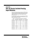
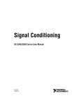
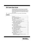
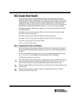
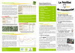
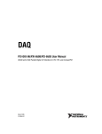
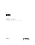
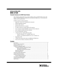
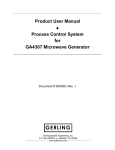
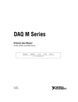
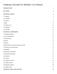
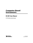
USER GUIDE
SCC-68
I/O Connector Block with 4 SCC Signal Conditioning Slots for DAQ Devices
The SCC-68 is an I/O connector block for easy signal connection to a
National Instruments M Series or E Series DAQ device. The SCC-68
features screw terminals and a general breadboard area for I/O signal
connection, and bus terminals for external power and grounding. The
SCC-68 has four SCC slots for use in integrating thermocouple, strain
gauge, RTD input, frequency input, current input, voltage attenuator,
lowpass filter, load cell input, accelerometer, feedthrough, SPDT relay,
isolated digital I/O, and isolated voltage input SCC modules into the
measurement system.
Contents
Conventions ............................................................................................ 3
Using the SCC-68 Enclosure .................................................................. 4
Opening the Enclosure..................................................................... 4
Closing the Enclosure ...................................................................... 5
Stacking and Wall Mounting ........................................................... 6
Installing Rubber Feet...................................................................... 7
Connecting to the DAQ Device .............................................................. 8
Using the SCC-68 with 16 AI Channel M Series Devices .............. 8
Using the SCC-68 with 32 AI Channel M Series Devices .............. 8
Using the SCC-68 with a 68-Pin E Series Device ........................... 9
Using the SCC-68 with the NI 6025E, NI 6033E, or NI 6071E...... 10
SCC-68 Features ..................................................................................... 11
Screw Terminals .............................................................................. 12
Device Pinouts .......................................................................... 12
Wiring to Screw Terminals....................................................... 12
Integrated Strain Relief .................................................................... 12
SCC Modules................................................................................... 13
Breadboard Area .............................................................................. 13
Using the Temperature Sensor for Cold-Junction
Compensation (CJC) ..................................................................... 14
Cold Junction Temperature Measurement Accuracy ............... 15
Bus Terminals...................................................................................15
Power Supply....................................................................................16
Using SCC Modules with the SCC-68 ....................................................16
Supported SCC Modules ..................................................................17
Connecting Signals to SCC Modules in the SCC-68 .......................17
Power Supply Considerations...........................................................19
LED ...........................................................................................20
Installing the SCC Modules in the SCC-68......................................21
SCC Connector Pinouts.............................................................21
Direct Access to SCC signals....................................................23
Analog Input Measurement Considerations ............................................23
Differential .......................................................................................24
Single-Ended ....................................................................................24
Non-Referenced Single Ended (NRSE) ...........................................25
Grounded Signal Sources ..........................................................25
Floating Signal Sources.............................................................26
Ground-Referenced Single Ended (RSE).........................................26
Grounded Signal Sources ..........................................................26
Floating Signal Sources.............................................................26
Taking Measurements with NI-DAQmx .................................................27
Configuring the SCC-68...................................................................28
Configuring the SCC-68 as an SCC Carrier..............................28
Configuring the SCC-68 as a Screw Terminal Accessory ........28
Configuring Channels and Tasks......................................................29
Configure a Task .......................................................................29
Configure Global Virtual Channels...........................................31
Using Your Task in an Application..................................................32
Specifications...........................................................................................33
Quick Reference Guides ..........................................................................38
SCC-68 User Guide
2
ni.com
Conventions
The following conventions are used in this manual:
<>
Angle brackets that contain numbers separated by an ellipsis represent
a range of values associated with a bit or signal name—for example,
AO <3..0>.
»
The » symbol leads you through nested menu items and dialog box options
to a final action. The sequence File»Page Setup»Options directs you to
pull down the File menu, select the Page Setup item, and select Options
from the last dialog box.
This icon denotes a note, which alerts you to important information.
This icon denotes a caution, which advises you of precautions to take to
avoid injury, data loss, or a system crash. When this symbol is marked on
the product, refer to the Read Me First: Safety and Radio-Frequency
Interference document, shipped with the product, for precautions to take.
When symbol is marked on a product, it denotes a warning advising you to
take precautions to avoid electrical shock.
When symbol is marked on a product, it denotes a component that may be
hot. Touching this component may result in bodily injury.
bold
Bold text denotes items that you must select or click in the software, such
as menu items and dialog box options. Bold text also denotes parameter
names.
italic
Italic text denotes variables, emphasis, a cross-reference, or an introduction
to a key concept. Italic text also denotes text that is a placeholder for a word
or value that you must supply.
monospace
Text in this font denotes text or characters that you should enter from the
keyboard, sections of code, programming examples, and syntax examples.
This font is also used for the proper names of disk drives, paths, directories,
programs, subprograms, subroutines, device names, functions, operations,
variables, filenames, and extensions.
SCC-XX
This name refers to any SCC module.
© National Instruments Corporation
3
SCC-68 User Guide
Using the SCC-68 Enclosure
Caution Refer to the Read Me First: Safety and Radio-Frequency Interference document
before removing equipment covers or connecting/disconnecting any signal wires.
4
5
3
2
1
6
7
8
9
2
1
2
3
4
5
SCC Slots
Screw Terminals
68-Pin I/O Connector
Enclosure Cover
Quick Reference Guide
6
7
8
9
Enclosure Base
External Power Screw Terminal
External Power Switch
Strain Relief Wire Entry
Figure 1. SCC-68 Parts Locator Diagram
Opening the Enclosure
To open the SCC-68, use a flathead screwdriver to loosen the captive screw
at the front of the device. After the screw is loosened, pull up on the front
of the enclosure cover to open. The top half of the SCC-68 enclosure can
be removed completely.
SCC-68 User Guide
4
ni.com
Closing the Enclosure
To close the SCC-68, align the two back tabs into the corresponding holes
at the back of the base, as shown in the detail in Figure 2. With the cover
and base of the enclosure aligned, snap the SCC-68 closed. To secure the
SCC-68 enclosure, use a flathead screwdriver to push the screw down
against the spring resistance and tighten the screw.
The captive screw must be used to secure the enclosure when connecting
hazardous voltage (>30 Vrms /42.4 Vpk /60 VDC) signals to an SCC-RLY01 module.
Caution
For safest operation of the SCC-68, NI recommends always using the captive screw
to keep the SCC-68 in a closed position.
Note
3
2
4
1
5
1
2
3
Strain Relief Posts
Snapping Latches
Captive Screw
4
5
Hinge Tabs
Strain-Relief Holes for Cable Ties
Figure 2. SCC-68 Enclosure Features
© National Instruments Corporation
5
SCC-68 User Guide
Stacking and Wall Mounting
The SCC-68 has grooves on the bottom of the enclosure that allow the
device to be stacked on top of other SCC-68 connector blocks.
The SCC-68 cannot be securely stacked onto another SCC-68 if the rear rubber feet
are attached.
Note
The SCC-68 also has mounting holes on the bottom of the device for secure
wall-mounting. The third mounting hole allows you to mount the SCC-68
onto a wall sideways or inverted. Refer to Figures 3 and 4 for more
information about the location and use of these enclosure features.
17.78 cm
(7.00 in.)
12.70 cm
(2.50 in.)
3
12.70 cm
(5.00 in.)
2.54 cm
(1.00 in.)
3.51 cm
(1.38 in.)
1
24.46 cm
(9.63 in.)
17.78 cm
(7.00 in.)
2
1
2
Mounting Holes
Directional Mounting Hole
3
I/O Connector Cable
Figure 3. SCC-68 Mounting Dimensions
SCC-68 User Guide
6
ni.com
Installing Rubber Feet
Rubber non-skid feet are shipped with the device that can be attached for
secure desktop use. To install the rubber feet, remove adhesive backing and
affix to the SCC-68 where indicated in Figure 4.
3
2
1
1
1
2
Rubber Feet
Wall-Mounting Holes
2
3
1
Stacking Grooves
Figure 4. SCC-68 Mounting Features
© National Instruments Corporation
7
SCC-68 User Guide
Connecting to the DAQ Device
The following sections describe how to connect the SCC-68 to the DAQ
device. The SCC-68 is designed to be used with M Series and E Series
DAQ devices only. Other 68-pin devices may not function properly with
the SCC-68.
Using the SCC-68 with 16 AI Channel M Series Devices
To use the SCC-68 with a 16 AI channel M Series device, complete the
following steps:
1.
Attach the quick reference guide, shown in Figures 21 and 22, to the
top of the SCC-68 enclosure as shown in Figure 1. The quick reference
guide for Connector 0 (included in the SCC-68 kit) shows the pin
assignments of the SCC-68 and other useful information.
2.
Attach the SCC-68 to the DAQ device using one of the following
cables:
3.
•
SHC68-68-EPM
•
SHC68-68
•
RC68-68
Proceed to the Taking Measurements with NI-DAQmx section for
information about using the SCC-68 in measurement applications.
Some M Series devices are available with a 37-pin connector. The SCC-68 cannot
be used with these devices.
Note
Using the SCC-68 with 32 AI Channel M Series Devices
The 32 AI channel M Series DAQ device has two connectors.
•
Connector 0 (AI 0-15)
•
Connector 1 (AI 16-31)
The SCC-68 can be used with Connector 0 or Connector 1.
To use the SCC-68 with a 32 AI channel M Series device using
Connector 0, complete the following steps:
1.
SCC-68 User Guide
Attach the quick reference guide, shown in Figures 21 and 22, to the
top of the SCC-68 enclosure as shown in Figure 1. The quick reference
guide for Connector 0 (included in the SCC-68 kit) shows the pin
assignments of the SCC-68 and other useful information.
8
ni.com
2.
3.
Attach the SCC-68 to Connector 0 of the DAQ device using one of the
following cables:
•
SHC68-68-EPM
•
SHC68-68
•
RC68-68
Proceed to the Taking Measurements with NI-DAQmx section for
information about using the SCC-68 in measurement applications.
To use the SCC-68 with a 32 AI channel M Series device using
Connector 1, complete the following steps:
1.
2.
Attach the SCC-68 to Connector 1 of the DAQ device using one of the
following cables:
•
SHC68-68-EPM
•
SHC68-68
•
RC68-68
Refer to Figure 22 in the Quick Reference Guides section for the quick
reference guide for the SCC-68 connected to Connector 1 of the DAQ
device. The guide shows the pin assignments of the SCC-68 and other
useful information. Attach a copy of this guide to the top of the
SCC-68 enclosure as shown in Figure 1.
Using the SCC-68 with a 68-Pin E Series Device
To use the SCC-68 with a 68-pin E Series device, complete the following
steps:
1.
2.
© National Instruments Corporation
Attach the SCC-68 to the DAQ device using one of the following
cables:
•
SH68-68-EP
•
R68-68
Refer to Figure 23 in the Quick Reference Guides section for the quick
reference guide for the SCC-68 connected to the E Series DAQ device.
The guide shows the pin assignments of the SCC-68 and other useful
information. Attach a copy of this guide to the top of the SCC-68
enclosure as shown in Figure 1.
9
SCC-68 User Guide
Using the SCC-68 with the NI 6025E, NI 6033E, or NI 6071E
To use the SCC-68 with the NI 6025E, NI 6033E, or NI 6071E, complete
the following steps:
1.
Attach the SCC-68 to the DAQ device using an SH1006868 cable. This
cable has two 68-pin connectors labeled MIO 16 and Extended I/O.
Connect the MIO 16 connector to the SCC-68. Refer to Figure 5.
SCC-68
MIO Connector
E Series
100-Pin Device
Extended
I/O Connector
SCB-68 or
Other
Terminal
Block
SH1006868 Cable
Figure 5. Connecting a 100-Pin DAQ Device to an SCC-68 Connector Block and
Another Terminal Block
You cannot use the Extended I/O connector with an SCC-68. Use
another terminal block such as the SCB-68 or CB-68LPR with the
Extended I/O connector.
2.
SCC-68 User Guide
Refer to Figure 23 in the Quick Reference Guides section for the quick
reference guide for the SCC-68 connected to the E Series DAQ device.
The guide shows the pin assignments of the SCC-68 and other useful
information. Attach a copy of this pinout to the top of the SCC-68
enclosure as shown in Figure 1.
10
ni.com
SCC-68 Features
The following sections describe the hardware features of the SCC-68.
4
3
5
FOR PATENTS: NI.COM/PATENTS
63
24
27
29
32
4
7
9
12
52
17
49
47
SW1
FRONT
GND
30
31
+5V
65
66
EXTERNAL
POWER
33
34
SELF POWER
(DEFAULT)
2
68
4.75-5.25V
2A MAX
70
13
6
71
1
39
3
15
37
1
38
SCC
Mod 1
SCC
Mod 2
SCC
Mod 3
18
SCC
Mod 4
5
40
6
35
41
2
42
36
43
46
10
44
11
45
48
8
16
57
23
56
25
58
7
59
60
26
64
28
61
50
8
51
53
19
62
74
67
75
20
69
72
USE SCC CONNECTOR BACKSHELL FOR HAZARDOUS
LIVE SIGNALS (>42.4 Vpk / 60VDC)
73
22
80
SCC-68
76
77
SCC Mod 1
SCC Mod 2
SCC Mod 3
SCC Mod 4
78
ROUTE SCC SIGNAL WIRES
ON THIS SIDE
9
54
81
21
82
55
83
79
C-68
NI SC
10
1
2
3
4
5
SCC Slots
SCC Screw Terminals
68-Pin I/O Connector
External Power Switch
External Power Screw Terminals
6
7
8
9
10
DIO Screw Terminals
AI Screw Terminals
Bus Screw Terminals
AO Screw Terminals
Strain-Relief Wire Entry
Figure 6. SCC-68 Features
© National Instruments Corporation
11
SCC-68 User Guide
Screw Terminals
The SCC-68 provides screw terminals for easy I/O connectivity.
Device Pinouts
For a list of pins and their corresponding signal assignments, refer to the
quick reference guide for the device, which can be found in the Quick
Reference Guides section of this document. Refer to the DAQ device
documentation for additional details about the DAQ device signals.
Wiring to Screw Terminals
To connect signals to the SCC-68, complete the following steps while
referring to Figure 1.
1.
Disconnect the 68-pin cable from the SCC-68.
2.
Remove the top cover as directed in the Opening the Enclosure section.
3.
Slide the signal wires through the wire entry strain-relief opening. For
more information about using strain relief with the SCC-68, refer to
the Integrated Strain Relief section.
4.
Connect the wires to the screw terminals by stripping off 7 mm
(0.28 in.) of the insulation, inserting the conductors into the terminals,
and tightening the screws.
5.
Close the top cover.
You can now connect the SCC-68 to the 68-pin I/O connector.
Integrated Strain Relief
Strain relief for the I/O connector wires is provided through a
labyrinth-style wire entry at the front of the SCC-68 device. For larger
gauge connector wires and jacketed cables, bundle the wires together and
secure the wires to the holes in the wire entry opening using the provided
cable ties.
For smaller gauge connector wires (26 AWG–30 AWG), thread the wires
through the strain-relief posts located on the side opposite the wire entry.
By lacing the connector wires through these posts, movement is limited.
Note Route all SCC signals through the left wire-entry side of the SCC-68. Route all other
signals through the right wire-entry side.
SCC-68 User Guide
12
ni.com
45
8
50
53
69
72
USE SCC CONNECTOR BACKSHELL FOR HAZARDOUS
LIVE SIGNALS (>42.4 Vpk / 60VDC)
73
SCC-68
76
77
SCC Mod 1
SCC Mod 2
SCC Mod 3
SCC Mod 4
78
ROUTE SCC SIGNAL WIRES
ON THIS SIDE
11
28
48
61
16
51
62
19
67
74
20
75
22
80
54
81
21
82
55
83
79
1
1
NI SC
C-68
2
Left Wire Entry
1
Small Gauge Strain Relief Posts
Right Wire Entry
2
Larger Gauge Cable Tie Holes
Figure 7. SCC-68 Strain Relief
SCC Modules
The SCC-68 can accept SCC modules for integrating signal conditioning
into your application. Refer to the Using SCC Modules with the SCC-68
section for more information.
Breadboard Area
The SCC-68 features a general breadboard area for custom circuitry such
as filtering or attenuation. For soldering components to the underside of the
breadboard, remove the printed circuit board by carefully snapping it loose
from the SCC-68 enclosure. To desolder on the SCC-68, vacuum-type tools
work best.
© National Instruments Corporation
13
SCC-68 User Guide
Using the Temperature Sensor for Cold-Junction Compensation (CJC)
The SCC-68 has a temperature sensor connected to screw terminals 70 and
71 as shown in Figure 8. Refer to the Specifications section for the formula
for converting the measured voltage on CJC+ to temperature.
+5V
R1
4,870 Ω
CJC+
RT
70
5 kΩ at 25 ˚C
71
AI GND
Figure 8. SCC-68 Temperature Sensor Connection
To use the temperature sensor for cold-junction compensation of
thermocouple measurements, connect CJC+ (terminal 70) to AI channel 7
of the SCC-68. Figure 9 shows the temperature sensor connected to AI 7.
CJC+
AI GND
70
71
3
37
38
5
6
41
42
43
10
57
23
56
AI 7
AI 15
AI GND
25
58
59
60
26
Figure 9. Connecting the CJC Sensor to Channel AI 7
You must also ensure that the temperature sensor is powered by one of the
following:
SCC-68 User Guide
•
The DAQ device. Move the power switch to SELF POWER (shown in
item 4 of Figure 6).
•
An external power supply. Refer to the Power Supply Considerations
section for more information.
14
ni.com
To remove power from the temperature sensor, complete the following
steps:
1.
Move the power switch to EXTERNAL POWER, shown in item 4 of
Figure 6.
2.
Leave the external power screw terminals, shown in item 5 of Figure 6,
unconnected.
Cold Junction Temperature Measurement Accuracy
Note For the most accurate thermocouple measurements, NI recommends using an
SCC-TC series module. For more information, refer to ni.com/products.
Temperature differences between the cold-junction temperature sensor and
the actual cold junction formed by a thermocouple connected to the screw
terminals will directly contribute to thermocouple measurement errors.
With minimal loading on the SCC-68 ±15V power supply, the temperature
difference between the screw terminals of the SCC-68 is typically less than
1 °C. Variations in the ambient temperature, SCC module heat dissipation,
and heat conducted along thermocouple wire can all contribute to
isothermal errors across the screw terminals.
For more information on thermocouple theory and use, refer to the Taking
Thermocouple Temperature Measurements tutorial at ni.com/zone.
Bus Terminals
The bus terminals provide an easy interface for supplying external power,
extra ground terminals, or grounding to any sensors or custom circuits used
in the SCC-68. There are two buses—Bus A and Bus B—where all four
screw terminals on each side are connected together internally. To use these
terminals, you may connect the power supply from an external source, and
then use the remaining three terminals to connect sensors or circuits inside
the SCC-68.
80
76
Bus B
77
78
81
Bus A
82
83
79
Bus A and Bus B are not connected to
any other signals on the SCC-68.
Figure 10. Bus Terminals
© National Instruments Corporation
15
SCC-68 User Guide
The bus terminals do not provide external power to the SCC modules
installed in the SCC-68 or to the +5V terminal. Refer to the Power Supply
Considerations section for information about providing power to SCC
modules in your application.
Power Supply
In most situations, the SCC-68 is powered by the DAQ device, eliminating
the need for an external power supply. The +5V power provided by the
DAQ device is distributed to all components in the SCC-68, including the
+5V screw terminal (pin 8). The +5V power on the DAQ device is current
limited. For more information about the power supply and possible
limitations, refer to the Power Supply Considerations section.
Using SCC Modules with the SCC-68
The SCC-68 has four SCC slots for integrating signal conditioning into
your applications. Each SCC slot can be used with any analog input or
digital I/O SCC modules. The SCC-68 is not compatible with analog output
or counter SCC modules.
If you use analog input SCC modules with the SCC-68, you must connect
AI SENSE to AI GND, as shown in Figure 11.
Note
62
67
AI SENSE
AI GND
20
22
54
21
55
Figure 11. Connecting AI SENSE to AI GND
SCC-68 User Guide
16
ni.com
Supported SCC Modules
The SCC-68 supports all analog input and digital I/O SCC modules.
Table 1 shows all SCC modules that are compatible with the SCC-68.
Table 1. SCC-68-Compatible SCC Modules
SCC Module
Type
SCC-AI0x
Isolated Voltage Input
SCC-TC0x
Thermocouple Input
SCC-LP0x
Lowpass Filters
SCC-SG0x
Strain Gauge Input
SCC-SG24
Load Cell Input
SCC-ACC01
Accelerometer Input
SCC-FT01
Feedthrough
SCC-RTD01
RTD Input
SCC-FV01
Frequency Input
SCC-CI20
Current Input
SCC-A10
Voltage Attenuation
SCC-DI01/DO01
Isolated Digital I/O
SCC-RLY01
SPDT Relay
Connecting Signals to SCC Modules in the SCC-68
Always refer to the specifications in the SCC-XX module user guide before
connecting signals. Exceeding specified module ratings can create a shock or fire hazard
and can damage any or all of the devices connected to the module.
Caution
The captive screw must be used to secure the enclosure when connecting
hazardous voltage (>30 Vrms /42.4 Vpk /60 VDC) signals to an SCC-RLY01 module.
Caution
Disconnect the 68-pin cable for the DAQ device before installing or removing any
SCC modules.
© National Instruments Corporation
17
SCC-68 User Guide
You must use an SCC connector backshell when connecting hazardous voltage
(>30 Vrms /42.4 Vpk /60 VDC) signals to an SCC-RLY01 module. Refer to Figure 12.
Caution
Figure 12. SCC Connector Backshell
Refer to the SCC-XX user documentation for additional safety information.
To connect an SCC module to the SCC-68, complete the following steps:
1.
Remove power from the signal lines.
2.
Strip insulation from the ends of the signal wires. Refer to the SCC-XX
user documentation for the exact strip length for the module.
3.
Insert the conductors into the screw terminals. The SCC-XX module
has a fixed screw-terminal receptacle and a removable screw-terminal
block, as shown in Figure 13.
1
XX
XX
C-
SC
4
3
2
1
2
1
SCC Screw-Terminal Receptacle
2
Removable Screw-Terminal Block
Figure 13. SCC-XX Two-Part Screw-Terminal System
4.
SCC-68 User Guide
Tighten the screws to 0.5 to 0.6 N · m (4.4 to 5.3 lb · in.) of torque.
18
ni.com
Power Supply Considerations
The +5V power provided by the DAQ device is distributed to all
components in the SCC-68 and is also used to generate ±15V power for
SCC modules. Figure 14 shows the power distribution of the SCC-68.
If your application exceeds the current limitation of the DAQ device, you
will need to connect an external power supply—such as the External Power
Supply for the SCC-68 Accessory (Part Number 779641-01)—to the
SCC-68. To use an external power supply with the SCC-68, connect the
power supply to the screw terminals shown in item 5 of Figure 6 and move
the power switch (shown in item 4 of Figure 6) to EXTERNAL POWER.
You may need an external power supply if you have SCC modules installed
and any of the following conditions apply to your application:
1
•
More than two SCC-AI0x or SCC-SG24 modules are installed in the
SCC-68
•
The cable connecting the DAQ device to the SCC-68 is longer
than 2 m
•
You measure less than 4.50 V between terminals 8 and 50 when the
SCC-68 is under full load1
•
You are using a PCMCIA device such as the NI DAQCard-6024E
•
You are using +5V to power custom circuitry on the breadboard area
If the +5V power from the DAQ device drops below about 4.5 V, SCC modules installed in the SCC-68 will not operate
properly. The LED in the SCC-68 will flash seven times per second to indicate this condition. There is no error or notification
in software.
© National Instruments Corporation
19
SCC-68 User Guide
Figure 14 shows the power supply path and power distribution of the
SCC-68.
External
Power Supply
GND
+5V
GND
SW1
PC or PXI
Chassis
Power
Supply
Current
Limiter
+5V (Filtered)
Filter
+15V
Switching
Power Supply –15V
+5V
SCC
Mod 2
Voltage
Monitor
DAQ Device
SCC
Mod 1
LED
SCC
Mod 3
+5V Screw
Terminal
(Pin 8)
GND
SCC
Mod 4
SCC-68
Figure 14. SCC-68 Power Distribution Block Diagram
LED
The LED in the SCC-68 shows the status of the power supply. The SCC-68
monitors the voltage of the +5V signal from the DAQ device, as shown in
Figure 14. Table 2 shows the correlation between power levels in the
SCC-68 and the LED status.
Table 2. SCC-68 Power Levels
Voltage on +5V Signal
LED Status
Meaning
≥4.5 V*
On
Power on
≥2 V and <4.5 V*
Blinking
Power insufficient†
<2 V
Off
Power is off or power
insufficient
* Due to component variations, the threshold for the LED can vary between 4.25 V
and 4.5 V.
† Refer to the Power Supply Considerations section for more information about supported
SCC module configurations and other SCC-68 power supply issues.
SCC-68 User Guide
20
ni.com
Installing the SCC Modules in the SCC-68
To install the SCC modules on the SCC slots of the SCC-68, plug the SCC
modules onto the appropriate connector block sockets. When properly
oriented, SCC modules plug easily onto the connector block socket. Never
force an SCC module onto the socket.
SCC Connector Pinouts
This section contains descriptions of all the signals carried by the 20-pin
sockets on the SCC-68 carrier. You can also access these signals by using
an SCC feedthrough module, such as the SCC-FT01. For more information
about the SCC-68 carrier connector locations, refer to the SCC Quick Start
Guide at ni.com/manuals. Refer to Figure 15 for the pin assignments of
the SCC sockets.
© National Instruments Corporation
21
SCC-68 User Guide
SCC-68 User Guide
22
ni.com
NC
NC
NC
NC
SCC Module 1
NC
NC
5V Ref
–15V
16 15
18 17
20 19
NC
NC
5V Ref
–15V
NC
NC
AI 9
AI GND
NC
D GND
AI 0
AI SENSE
NC
P0.0
+5V (Filtered)
AI GND
+15V
2 1
4 3
6 5
8 7
10 9
12 11
14 13
AI 0
AI 8
AI GND
D GND
P0.0
NC
AI 8
AI GND
NC
D GND
68
34
24
4
52
NC
NC
NC
NC
NC
NC
5V Ref
–15V
NC
AI 10
AI GND
NC
D GND
NC
NC
NC
SCC Module 3
16 15
18 17
20 19
AI 2
AI SENSE
NC
P0.2
+5V (Filtered)
AI GND
+15V
AI 2
AI 10
AI GND
D GND
P0.2
2 1
4 3
6 5
8 7
10 9
12 11
14 13
65
31
29
9
49
NC
NC
NC
5V Ref
–15V
NC
AI 11
AI GND
NC
D GND
Figure 15. SCC Module 20-Pin Connector Orientation and Pinout
SCC Module 2
16 15
18 17
20 19
AI 1
AI SENSE
NC
P0.1
+5V (Filtered)
AI GND
+15V
AI 1
AI 9
AI GND
D GND
P0.1
2 1
4 3
6 5
8 7
10 9
12 11
14 13
33
66
27
7
17
NC
NC
NC
SCC Module 4
16 15
18 17
20 19
AI 3
AI SENSE
NC
P0.3
+5V (Filtered)
AI GND
+15V
AI 3
AI 11
AI GND
D GND
P0.3
2 1
4 3
6 5
8 7
10 9
12 11
14 13
30
63
32
12
47
Direct Access to SCC signals
When no SCC module is installed in a socket, you can access the AI and
DIO signals on that SCC socket with screw terminals. The screw terminals
are located behind each SCC socket, as shown in Figure 6.
When an SCC module is installed, do not connect signals to the
five corresponding screw terminals behind the module. Doing so can result in
unpredictable behavior in your application.
Caution
Analog Input Measurement Considerations
You can measure analog input signals with the SCC-68 the following ways:
•
Connect AI signals to SCC modules
•
Connect AI signals to SCC-68 screw terminals which get routed to the
DAQ device
If you are not using SCC modules in the system, refer to the M Series User
Manual or the E Series Help for information about connecting analog input
signals.
If you are using SCC modules for some of the AI signals, you can also
measure other AI signals using the AI screw terminals in the SCC-68. Refer
to Figure 6 for the location of the AI screw terminals.
This section describes some considerations for connecting these AI signals
to the SCC-68. When using SCC analog input modules you should connect
AI SENSE to AI GND as shown in Figure 11. This section only addresses
measurement considerations for signal sources that are connected to analog
input channels not used by installed SCC modules
© National Instruments Corporation
23
SCC-68 User Guide
Table 3 summarizes the recommended input configurations for floating
signal and ground-referenced signal sources.
Table 3. Recommended AI Ground Reference Setting when SCC Modules are Installed*
Signal Source Type
AI Ground
Reference Setting
Floating Signal Sources
(Not Connected to Building Ground)
Ground-Referenced
Signal Sources
Differential (DIFF)
Best
Best
Referenced
Single-Ended (RSE)
Not Recommended
Not Recommended
Non-Referenced
Single-Ended
(NRSE)
Good
Not Recommended
*
This section assumes that when SCC modules are installed, AI SENSE and AI GND on the DAQ device are connected
together. If you are not using SCC modules in the system, refer to the M Series User Manual or the E Series Help for
information about connecting analog input signals.
Refer to the NI Developer Zone document, Field Wiring and Noise
Considerations for Analog Signals, for more information. To access this
document, go to ni.com/info and enter the info code rdfwin.
Differential
A differential (DIFF) connection is a connection in which the AI signal has
its own reference signal return path as described in the M Series User
Manual or the E Series Help.
Use differential input connections for any channel that meets any of the
following conditions:
•
The input signal is low-level (less than 1 V).
•
The leads connecting the signal to the device are greater than
3 m (10 ft).
•
The input signal requires a separate ground-reference point or return
signal.
•
The signal leads travel through noisy environments.
Single-Ended
A single-ended connection is a connection in which the device AI signal
is referenced to a ground that it can share with other input signals.
National Instruments M Series and E Series devices provide two
single-ended connection configurations.
SCC-68 User Guide
24
ni.com
Use single-ended input connections if the input signal meets the following
conditions.
•
The input signal is high-level (greater than 1 V).
•
The leads connecting the signal to the device are less than 3 m (10 ft).
•
The input signal can share a common reference point with other
signals.
Differential input connections are recommended for greater signal integrity
for any input signal that does not meet the preceding conditions.
Non-Referenced Single Ended (NRSE)
Refer to the NRSE connection considerations described in the M Series
User Manual or the E Series Help. If you have SCC modules installed in
the SCC-68, the following cases should also be noted.
Grounded Signal Sources
If you have SCC modules installed in the SCC-68, differential
measurements are recommended over NRSE measurements. When you
have SCC modules installed, connect AI GND to AI SENSE. If you
connect the ground of the signal source to AI SENSE, you are also shorting
it to AI GND. Connecting the ground of the signal source to AI GND
introduces a ground loop and ground-loop-induced errors. Figure 16 shows
this measurement error.
SCC-68
DAQ Device
Not Recommended
Ground-Referenced
Signal
+
–
AI
+
AI SENSE (Pin 62)
–
NRSE Mode
AI GND (Pin 67)
Figure 16. Ground-Referenced Signal Connected in NRSE Mode
© National Instruments Corporation
25
SCC-68 User Guide
The difference in potential between the ground of the signal source and
AI GND causes an error when measuring the signal. The amount of this
error depends on several factors including the length of the cable
connecting the DAQ device to the SCC-68 and the amount of current being
drawn by the SCC-68 from the DAQ device +5V power supply.
Floating Signal Sources
Floating signals can be measured in NRSE mode with AI SENSE and
AI GND connected together with certain limitations. This configuration
can have implications depending on the bias resistor requirements of the
signal source. Refer to the M Series User Manual or the E Series Help for
more information regarding floating source bias requirements.
SCC-68
Floating
Signal
+
–
DAQ Device
AI
+
AI SENSE (Pin 62)
–
NRSE Mode
AI GND (Pin 67)
Figure 17. Floating Signal Connected in NRSE Mode
Ground-Referenced Single Ended (RSE)
Refer to the RSE connection considerations described in the M Series User
Manual or the E Series Help. The following cases should also be noted.
Grounded Signal Sources
This configuration is not recommended as described in the M Series User
Manual or the E Series Help.
Floating Signal Sources
Connecting a floating signal source in RSE mode is not recommended.
When measuring floating signals with the SCC-68 configured for SCC
modules, use the NRSE measurement configuration.
SCC-68 User Guide
26
ni.com
If RSE is used to measure floating signals, there will be a measurement
error due to the current being drawn by the SCC-68 from the DAQ device
+5V power supply.
This potential will vary depending on the length of the cable connecting the
DAQ device to the SCC-68 and the amount of current being drawn from the
+5V power supply by the SCC-68. Figure 18 shows this measurement
error.
SCC-68
DAQ Device
Power Switch
+5V
+
Power for
SCC Modules and
CJC Sensor
–
+5V
+
–
Not Recommended
GND
AI
+
–
+
AI GND
(Pin 67)
I
+
Floating
Signal
VL
–
–
RL
RSE Mode
Figure 18. Floating Signal Connected in RSE Mode
Taking Measurements with NI-DAQmx
Before beginning any signal conditioning applications with the SCC-68,
make sure you have the following software and documentation materials:
❑ NI-DAQmx 8.1 or later software and documentation
❑ One of the following software packages for development:
–
LabVIEW
–
LabWindows™/CVI™ version 7.0 or later
–
Visual C++
–
Visual Basic
To install NI-DAQmx, refer to the DAQ Getting Started Guide.
© National Instruments Corporation
27
SCC-68 User Guide
Configuring the SCC-68
The SCC-68 can be configured as an SCC carrier and as a screw terminal
accessory. To configure the SCC-68 as both an SCC carrier and a screw
terminal accessory, you need to follow the configuration instructions in the
Configuring the SCC-68 as an SCC Carrier section and the Configuring
the SCC-68 as a Screw Terminal Accessory section.
Configuring the SCC-68 as an SCC Carrier
To configure the SCC-68 as an SCC carrier accessory for a DAQ device
using Measurement & Automation Explorer (MAX), complete the
following steps:
1.
Navigate to MAX by selecting Start»All Programs»National
Instruments»Measurement & Automation.
2.
In the left pane of MAX, expand Devices and Interfaces.
3.
Right-click NI-DAQmx Devices and select Create New NI-DAQmx
Device»NI-DAQmx SCC Connector Block»SCC-68.
4.
Select the DAQ device that the SCC-68 is connected to from the DAQ
Device menu. For devices with multiple connectors, select the
connector that is cabled to the DAQ device.
5.
For each SCC module physically installed in the SCC-68 carrier, add
a corresponding entry in the SCC-68 configuration window. To add the
SCC, click the Socket drop-down list and select the correct module.
6.
If the module name does not appear in the list, either the module is not
allowed in that location or you do not have the current version of
NI-DAQ. If you do not have the current version of NI-DAQ, download
it from ni.com/downloads.
7.
Click OK after completing all SCC entries to finish the configuration
process.
Configuring the SCC-68 as a Screw Terminal
Accessory
To configure the SCC-68 as a screw terminal accessory for a DAQ device
using Measurement & Automation Explorer (MAX), complete the
following steps:
SCC-68 User Guide
1.
Right-click the DAQ device that the SCC-68 is connected to from the
DAQ Device menu and choose Properties.
2.
Click the Accessory tab and select SCC-68.
28
ni.com
Configuring Channels and Tasks
This section applies only if you are programming the device using
NI-DAQmx or NI application software.
A physical channel is a terminal or pin at which you can measure or
generate an analog or digital signal. A virtual channel is a collection or
settings such as a name, a physical channel, input terminal connections, the
type of measurement or generation, and can include scaling information.
In NI-DAQmx, virtual channels are integral to every measurement. In
NI-DAQmx, use the DAQ Assistant, accessible from MAX or NI
application software, to configure virtual channels and measurement tasks.
Refer to the DAQ Assistant Help and the Measurement & Automation
Explorer Help for NI-DAQmx. You also can configure virtual channels with
the NI-DAQmx API in your application program.
A task, an important concept for NI-DAQmx, is a collection of one or more
virtual channels with timing, triggering, and other properties. Conceptually,
a task represents a measurement or generation you want to perform. You
can set up and save all of the configuration information in a task and use the
task in an application.
In NI-DAQmx, you can configure virtual channels as part of a task or
separate from a task. Virtual channels created inside a task are local virtual
channels. Virtual channels defined outside a task are global virtual
channels. You can create global virtual channels in MAX or in your
application software and then save them in MAX. You can use global
virtual channels in any application or add them to a number of different
tasks. If you modify a global virtual channel, the change affects all tasks in
which you reference that global virtual channel.
Configure a Task
When using NI-DAQmx, configure tasks with the DAQ Assistant. To
create tasks using the SCC-68, you must have NI-DAQmx version 8.1
or later.
•
To launch the DAQ Assistant in MAX, right-click Data
Neighborhood and select Create New. In the Create New window,
select NI-DAQmx Task and click Next. If you are using a remote RT
target, expand your target, then right-click Data Neighborhood and
select Create New.
•
You also can open the DAQ Assistant directly within NI application
software. Refer to the help of your software package for more details.
© National Instruments Corporation
29
SCC-68 User Guide
The DAQ Assistant prompts you to create a new task.
1.
Select an I/O type, such as analog input. For thermocouple
measurements, you must first ensure the hardware is configured
correctly and that the SCC-68 has been configured in MAX. For more
information, refer to the Configuring the SCC-68 section.
2.
Select the measurement or generation to perform based on the
hardware functionality of the module. Table 1 lists the measurement
types in NI-DAQmx and how they correspond to the SCC modules. For
additional information about SCC-XX module-specific channel/task
settings, refer to the SCC Quick Start Guide and the SCC-XX module
user guide for the SCC device.
3.
Select the sensor to use, if applicable for that measurement.
4.
Select the physical channel(s) from which to create local virtual
channels in the task. Alternatively, you can add existing global virtual
channels to the task or copy information from an existing global virtual
channel to the local virtual channel. Click Next.
5.
If you launched the DAQ Assistant from MAX, type the new task
name. Click Finish.
6.
Set any timing and triggering information for the task.
Figure 19. A Task in the DAQ Assistant
SCC-68 User Guide
30
ni.com
Configure Global Virtual Channels
If you want to use virtual channels in multiple NI-DAQmx tasks or
applications, configure global virtual channels with the DAQ Assistant.
You can launch the DAQ Assistant to create a global virtual channel in
MAX or in LabVIEW.
•
To open the DAQ Assistant in MAX, right-click Data Neighborhood
and select Create New. In the Create New window, select NI-DAQmx
Global Virtual Channel and click Next.
•
To open the DAQ Assistant directly in LabVIEW to create a global
virtual channel, drop a DAQmx Global Channel control on the front
panel, right-click it, and select New DAQmx Channel.
The DAQ Assistant prompts you to create a new global virtual channel by
selecting an I/O type, such as analog input, the measurement or generation
to perform, the sensor applicable for that measurement, and the physical
channel from which to create a global virtual channel.
The DAQ Assistant prompts you to create a new global virtual channel.
1.
Select an I/O type, such as analog input.
2.
Select the measurement or generation to perform.
3.
Choose the sensor to use, if applicable for that measurement. A dialog
box opens for the task you have specified.
4.
Select the physical channel from which to create a global virtual
channel. Alternatively, you can copy information from an existing
global virtual channel. Click Next.
5.
Type the new global virtual channel name. Click Finish.
6.
Configure the onboard CJC sensor, if necessary.
To use the onboard CJC sensor for thermocouple measurements,
ensure that the CJC sensor is wired to AI 7, then select Built-In for the
CJC source. If this option is not available, check your configuration.
For more information, refer to the Configuring the SCC-68 section. For
CJC sensor wiring instructions, refer to the Using the Temperature
Sensor for Cold-Junction Compensation (CJC) section.
7.
Select the terminal configuration. Refer to the Analog Input
Measurement Considerations section for more information about this
setting.
8.
Save your configuration.
9.
Click Test. Verify your data in the window that opens. If the data is
incorrect, verify the settings in the DAQ Assistant window.
© National Instruments Corporation
31
SCC-68 User Guide
You now can use the global virtual channel in an application or add the
global channel to a task. Refer to the DAQ Assistant Help for more
information about creating tasks and virtual channels and using them in an
application.
In LabWindows/CVI and Measurement Studio, you cannot directly create
a global virtual channel; you must create them in MAX as previously
described.
Using Your Task in an Application
Complete the following steps to use a measurement task in your
application. Refer to the DAQ Assistant Help for more information about
using a task or generating code.
To run examples without hardware installed, you can use NI-DAQmx
simulated devices. In MAX, refer to the Measurement & Automation
Explorer Help for NI-DAQmx by selecting Help»Help Topics»
NI-DAQmx for instructions about creating NI-DAQmx simulated devices
and importing NI-DAQmx simulated device configurations to physical
devices.
LabVIEW
1.
Open a blank VI in LabVIEW.
2.
Place the following constant on the block diagram from the functions
palette: NI Measurement»DAQmx-Data Acquisition»DAQmx
Task Name Constant.
3.
Select the task from the pull-down menu.
4.
Right-click the VI and select Generate Code»Example to generate
the code to run the task.
5.
Run the program from the front panel.
LabWindows/CVI
Refer to ni.com/info and enter the information code rddq73 for
step-by-step instructions for using a task in LabWindows/CVI.
Measurement Studio
Refer to ni.com/info and enter the information code rddqms for
step-by-step instruction for using a task in Measurement Studio.
SCC-68 User Guide
32
ni.com
Specifications
This appendix lists the SCC-68 specifications. These ratings are typical at
25 °C unless otherwise stated.
Power Requirement
Power consumption (at +5 VDC, ±5%)
Typical ............................................ 1 mA with no signal
conditioning installed
The maximum power consumption of the SCC-68 is a function of the SCC modules
installed and any circuits constructed on the general-purpose breadboard area. Refer to the
Power Supply Considerations section for more information.
Note
External Power Supply Requirements
Using an external power supply is optional. Any external power supply
used with the SCC-68 must meet the following requirements.
Voltage output........................................ 4.75 V min,
5.25 V max
Current output ........................................ 2 A max;
minimum current requirement
is load dependent.
External Power Supply Protection
The SCC-68 external power supply screw terminal is protected against
overcurrent, overvoltage, and reverse voltage.
Overcurrent ............................................ Fused at 2 ADC
Overvoltage and reverse voltage............ ±20 VDC max
±15V Power Supply
The ±15V power supply is only accessible by SCC modules. You may
access it using an SCC-FT01 module. Refer to Figure 14 and Figure 15.
Tolerance................................................ ±5%
Max load current .................................... 50 mA
© National Instruments Corporation
33
SCC-68 User Guide
Temperature Sensor
Temperature sensor
Accuracy..........................................±0.3 °C over a 0 to 55 °C range
Type.................................................Thermistor
Convert the voltage to temperature using the following Steinhart-Hart
equation:
1
T = --------------------------------------------------------------------- – 273.15
3
A + B ( ln ( R T ) ) + C ( ln ( R T ) )
where
A = 1.2873851 × 10⁻³
B = 2.3575235 × 10⁻⁴
C = 9.4978060 × 10⁻⁸
R1 VT
R T = ------------------( 5 – VT )
where
R1 = 4,870 Ω
VT is the CJC voltage measurement
For more information about the temperature sensor, refer to the Using the
Temperature Sensor for Cold-Junction Compensation (CJC) section.
SCC-68 User Guide
34
ni.com
Physical
5.30 cm
(2.09 in.)
17.78 cm
(7.00 in.)
24.46 cm
(9.63 in.)
NI SC
C-68
Figure 20. SCC-68 I/O Connector Block Dimensions
Weight .................................................... 623.7 g (1 lb 6 oz)
I/O connectors ........................................ One 68-pin male SCSI connector
SCC sockets
Number of sockets .......................... 4
SCC types supported....................... Analog input,
digital input/output, feedthrough
Screw terminals...................................... 84 (54 AI, AO, DIO; 20 SCC;
8 bus; 2 external power)
Wire gauge ............................................. 14–26 AWG
(0.14 mm2–1.5 mm2)
© National Instruments Corporation
35
SCC-68 User Guide
Tightening torque ...................................0.5 to 0.6 N · m
(4.4 to 5.3 lb · in.)
Strip length .............................................7 mm (0.27 in.)
Maximum Working Voltage
Caution Refer to the DAQ device documentation for the voltage specifications for the
DAQ device.
Ensure that signals connected to SCC modules are used within the voltage ratings
of the modules to which they are connected. Refer to the SCC-XX user manual for the
voltage specifications for the SCC module.
Caution
Maximum working voltage refers to the signal voltage plus the
common-mode voltage.
Channel-to-earth .....................................11 VDC,
Measurement Category I
Caution Do not use the SCC-68 for connections to signals or for measurements within
Categories II, III, or IV.
Environmental
Operating temperature ............................0 to 55 °C
Storage temperature ................................–20 to 70 °C
Humidity .................................................5 to 90% RH, noncondensing
Maximum altitude...................................2,000 meters
Pollution Degree (indoor use only) ........2
Shock and Vibration
Operational shock ...................................30 g peak, half-sine, 11 ms pulse
(Tested in accordance with
IEC-60068-2-27. Test profile
developed in accordance with
MIL-PRF-28800F.)
Random vibration
Operating .........................................5 to 500 Hz, 0.3 grms
Nonoperating ...................................5 to 500 Hz, 2.4 grms
(Tested in accordance with
IEC-60068-2-64.)
SCC-68 User Guide
36
ni.com
Nonoperating random vibration profiles for the SCC-68 exceeds the requirements of
MIL-PRF-28800F, Class 3.
Note
Safety
This product is designed to meet the requirements of the following
standards of safety for electrical equipment for measurement, control,
and laboratory use:
Note
•
IEC 61010-1, EN-61010-1
•
UL 61010-1, CAN/CSA-C22.2 No. 61010-1
For UL and other safety certifications, refer to the product label or visit
ni.com/certification, search by model number or product line, and click the
appropriate link in the Certification column.
Electromagnetic Compatibility
This product is designed to meet the requirements of the following
standards of EMC for electrical equipment for measurement, control,
and laboratory use:
Note
•
EN 61326 EMC requirements; Minimum Immunity
•
EN 55011 Emissions; Group 1, Class A
•
CE, C-Tick, ICES, and FCC Part 15 Emissions; Class A
For EMC compliance, operate this device according to product documentation.
CE Compliance
This product meets the essential requirements of applicable European
Directives, as amended for CE marking, as follows:
•
73/23/EEC; Low-Voltage Directive (safety)
•
89/336/EEC; Electromagnetic Compatibility Directive (EMC)
Refer to the Declaration of Conformity (DoC) for this product for any additional
regulatory compliance information. To obtain the DoC for this product, visit
ni.com/certification, search by model number or product line, and click the
appropriate link in the Certification column.
Note
Waste Electrical and Electronic Equipment (WEEE)
EU Customers At the end of their life cycle, all products must be sent to a WEEE recycling
center. For more information about WEEE recycling centers and National Instruments
WEEE initiatives, visit ni.com/environment/weee.htm.
© National Instruments Corporation
37
SCC-68 User Guide
Quick Reference Guides
This section provides the quick reference guides for use with Connector 0
and Connector 1 of 68-pin M Series devices, and E Series devices. The
quick reference guides provide information about pin placements, their
corresponding signal assignments, and wire-stripping length for signal
connections.
SCC-68 User Guide
38
ni.com
© National Instruments Corporation
39
SCC-68 User Guide
SCC Mod 1
SCC Mod 2
17 P0.1
SCC Mod 4
47 P0.3
1
2
8
57 AI 7
61 AI 12
28 AI 4
64 AI GND
26 AI 13
60 AI 5
59 AI GND
58 AI 14
25 AI 6
56 AI GND
23 AI 15
Strip Gauge
55 AO GND
21 AO 1
54 AO GND
22 AO 0
20 APFI 0
67 AI GND
62 AI SENSE
FOR SCC ANALOG
MODULES CONNECT
AI SENSE TO AI GND
.27 in.(7 mm)
BUS A
75 SHIELD
74 SHIELD
19 P0.4
51 P0.5
16 P0.6
48 P0.7
11 PFI 0/P1.0
10 PFI 1/P1.1
43 PFI 2/P1.2
42 PFI 3/P1.3
41 PFI 4/P1.4
6 PFI 5/P1.5
5 PFI 6/P1.6
38 PFI 7/P1.7
37 PFI 8/P2.0
3 PFI 9/P2.1
71 AI GND
70 CJC+
P/N 193574C-01
BUS B
SHIELD 73
SHIELD 72
D GND 69
D GND 53
D GND 50
+5V
PFI 10/P2.2 45
D GND 44
PFI 11/P2.3 46
D GND 36
PFI 12/P2.4
D GND 35
PFI 13/P2.5 40
D GND 18
PFI 14/P2.6
D GND 15
PFI 15/P2.7 39
D GND 13
SCC-68 Reference Label
M Series Connector 0 Devices
Figure 21. Quick Reference Guide for M Series 68-Pin Connector 0 DAQ Device
SCC Mod 3
49 P0.2
9 D GND
7 D GND
4 D GND
52 P0.0
32 AI GND
12 D GND
29 AI GND
27 AI GND
24 AI GND
30 AI 3
63 AI 11
66 AI 9
34 AI 8
65 AI 2
31 AI 10
33 AI 1
68 AI 0
SCC-68 User Guide
40
ni.com
SCC Mod 1
SCC Mod 2
SCC Mod 4
1
2
8
BUS B
SHIELD 73
SHIELD 72
D GND 69
D GND 53
D GND 50
+5V
P0.26 45
D GND 44
P0.27 46
D GND 36
P0.28
D GND 35
P0.29 40
D GND 18
P0.30
D GND 15
P0.31 39
D GND 13
57 AI 23
.27 in.(7 mm)
BUS A
Strip Gauge
* NC on some devices
55 AO GND
21 AO 3*
54 AO GND
22 AO 2*
74 SHIELD
75 SHIELD
20 APFI 1
67 AI GND
62 AI SENSE 2
FOR SCC ANALOG
MODULES CONNECT
AI SENSE TO AI GND
61 AI 28
28 AI 20
64 AI GND
26 AI 29
60 AI 21
59 AI GND
58 AI 30
25 AI 22
56 AI GND
23 AI 31
19 P0.12
51 P0.13
16 P0.14
48 P0.15
11 P0.16
10 P0.17
43 P0.18
42 P0.19
41 P0.20
6 P0.21
5 P0.22
38 P0.23
37 P0.24
3 P0.25
71 AI GND
70 CJC+
SCC-68 Reference Label
M Series Connector 1 Devices
Figure 22. Quick Reference Guide for M Series 68-Pin Connector 1 DAQ Device
SCC Mod 3
47 P0.11
12 D GND
49 P0.10
9 D GND
17 P0.9
7 D GND
52 P0.8
4 D GND
63 AI 27
32 AI GND
31 AI 26
29 AI GND
66 AI 25
27 AI GND
30 AI 19
65 AI 18
34 AI 24
33 AI 17
24 AI GND
68 AI 16
© National Instruments Corporation
41
SCC-68 User Guide
17 P0.1
SCC Mod 2
52 P0.0
SCC Mod 1
SCC Mod 4
47 P0.3
8
BUS B
SHIELD 73
SHIELD 72
D GND 69
D GND 53
D GND 50
+5V
EXT STROBE 45
D GND 44
AI HOLD COMP 46
D GND 36
CTR 0 OUT 2
D GND 35
CTR 1 OUT 40
D GND 18
FREQ OUT 1
D GND 15
D GND 39
D GND 13
.27 in.(7 mm)
BUS A
75 SHIELD
74 SHIELD
19 P0.4
51 P0.5
16 P0.6
48 P0.7
55 AO GND
21 AO 1*
54 AO GND
22 AO 0*
20 AO EXT REF*
67 AI GND
62 AI SENSE
FOR SCC ANALOG
MODULES CONNECT
AI SENSE TO AI GND
61 AI 12
28 AI 4
64 AI GND
26 AI 13
60 AI 5
59 AI GND
58 AI 14
25 AI 6
56 AI GND
23 AI 15
57 AI 7
Strip Gauge
* NC on some devices
11 PFI 0/AI START TRIG
10 PFI 1/AI REF TRIG
43 PFI 2/AI CONV CLK
42 PFI 3/CTR 1 SRC
41 PFI 4/CTR 1 GATE
6 PFI 5/AO SAMP CLK
5 PFI 6/AO START TRIG
38 PFI 7/AI SAMP CLK
37 PFI 8/CTR 0 SRC
3 PFI 9/CTR 0 GATE
71 AI GND
70 CJC+
SCC-68 Reference Label
E Series Devices
Figure 23. Quick Reference Guide for E Series DAQ Device
SCC Mod 3
49 P0.2
12 D GND
9 D GND
7 D GND
4 D GND
63 AI 11
32 AI GND
31 AI 10
29 AI GND
66 AI 9
27 AI GND
30 AI 3
65 AI 2
34 AI 8
33 AI 1
24 AI GND
68 AI 0
National Instruments, NI, ni.com, and LabVIEW are trademarks of National Instruments Corporation.
Refer to the Terms of Use section on ni.com/legal for more information about National
Instruments trademarks. Other product and company names mentioned herein are trademarks or trade
names of their respective companies. For patents covering National Instruments products, refer to the
appropriate location: Help»Patents in your software, the patents.txt file on your CD, or
ni.com/patents.
© 2006 National Instruments Corporation. All rights reserved.
374748A-01
Aug06