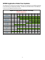
1
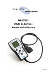
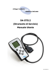
DA-ST512
(Service Tool)
User’s Manual
V3.2 04-04-13
2
Contents
Important Information
4
General Notice
4
Product Warranty
4
Product Terms & Conditions
5
Introduction
6
Getting to Know the Device
6
Device Registration and Set-up
8
Installing the DA App Hub
8
Registering your DA-ST512
9
Updating the DA-ST512 Device
10
DA-ST512 Software Updating
10
Advanced Software Updating
11
DA-ST512 Trial Applications
11
DA-ST512 Applications
12
DA-ST512 Menu Application
12
DA-ST512 Basic Operation
13
Service Interval Reset (SIR)
14
Electronic Park Brake Release (EPBR)
16
Tight Tolerance Mode Toggle (TTMT)
18
Transport Mode Toggle (TMT)
20
DPF Adaptions Reset (DPFAR)
22
DPF Dynamic Regeneration (DPFDR)
24
J2534 IDS/SDD Operation Mode
26
Device Recovery
28
Device Specification
28
Troubleshooting
29
Technical Support
30
Related Products
30
3
Important Information
General Notice
The DA–ST512 hand held device has been designed and tested to comply with modern vehicle
protocols. However, some vehicle models are not in full compliance with these protocols for
various reasons.
While Diagnostic Associates‟ testing and the experience of its many product users have shown
the unit to be safe and reliable, there is an inherent risk in using any product that may
potentially affect the operation or driveability of your vehicle.
If you are concerned about the operation of your vehicle at any time while using these products:
Pull off the roadway immediately or as soon as it is safe to do so (if applicable).
Disconnect the device from the vehicle OBDII connector.
Consult your local car dealership or garage.
This User Manual is updated on a regular basis to ensure its content is up-to-date. Every effort
is made to ensure that the latest version is supplied with your product, however this is not
always practical. As a result you should always consult the Diagnostic Associates website to
determine if you have the latest version.
Product Warranty
Diagnostic Associates Limited guarantees that every DA-ST512 hand held device is free from
physical defects in material and workmanship under normal use for twelve months from the date
of purchase.
4
Product Terms & Conditions
In no event shall Diagnostic Associates Limited‟s liability exceed the price paid for the product.
Diagnostic Associates shall be exempt from all other claims whether based upon direct, indirect,
special, incidental, or consequential damages resulting from the use of this product, its
accompanying software, or its documentation.
Diagnostic Associates Limited makes no warranty or representation, expressed, implied,
statutory, with respect to its products or the contents or use of this documentation and
accompanying software, and specifically disclaims its quality, performance, merchantability,
fitness for any particular purpose. Diagnostic Associates Limited reserves the right to revise
update its products, software, or documentation without obligation to notify any individual
entity.
or
all
or
or
or
If you are not in agreement with these terms then you are advised to return the product, prior to
use, immediately for a full refund.
5
Introduction
Thank you for choosing the DA-ST512 hand held device. This is a Jaguar Land Rover (JLR)
approved device that can be used for a vast majority of the current JLR vehicles that support the
diagnostic, configuration and set-up applications developed for this device (all of which appear
on IDS/SDD).
The device is pre-loaded with a number of these applications that have a wide ranging use on
the JLR range of vehicles. This is only a small sub-set of applications that are available, and
more applications can be loaded onto the device by simply purchasing them from the Diagnostic
Associates App Hub . More details on how to do this are shown later in this document.
The device works in a stand-alone mode which means that there is no need for a connection to a
PC or the IDS/SDD tool. The only exception to this is when the device is used in pass-through
mode, where it can be used as a J2534 pass-through communication device and used as part of
IDS/SDD, negating the need for a separate vehicle communications device.
The DA-ST512 hand held device is easily updated using the Diagnostic Associates App Hub which
is provided for free download from our website. This PC application will allow you to connect the
DA-ST512 to your PC to check for updates to your currently installed set of applications, to install
recently purchased additional applications, or to remove (temporarily) applications that are
currently installed. Once an additional application has been purchased the tool keeps a track of
what you have bought, and what you have installed at what version.
Note: During device update via USB, there is no need to have the device powered up via its
OBDII connector.
The DA-ST512 device receives its power directly from the vehicle, and once plugged into the
vehicle it will identify the vehicle before displaying the dynamic menu screen which will contain
all applications that you have loaded on the device that are applicable to that vehicle. From this
point you simply navigate to one of the installed applications, and select it to start the selected
routine. Once complete the device will indicate via the screen or through its built in sounder that
the application has been completed.
The device can be reset in either power mode (USB or vehicle power), by removing the power
source and re-connecting it. Doing this will simply re-power the device and start from the
beginning. No installed applications will be lost during a reset.
Getting to Know the Device
Your package includes a DA-ST512 hand held device, a 1 metre USB 2.0 cable and this user
guide.
6
There are seven main parts to the device and these are shown on the picture above.
Vehicle OBDII Connector : This is the end that connects to the vehicle OBDII diagnostic
connector and provides power to the device and connection to the vehicle communications
networks.
USB Connector : This connects the device to a PC via a USB (A-B) cable and is used to
update the device software when updates are available, or connect to SDD. This is
accessed by opening the rubber USB cover.
SD Card Slot : The use of this is application specific and the user will be notified if an SD
card is required during and application. This is accessed by removing the port cover.
Keypad : The 6 button keypad is used for navigating menus, selecting screen items or
acknowledging user inputs during application use.
LCD Screen : The back-lit LCD screen is used as the primary source for instructions and
feedback to the operator during use. It is an automatically adjusting contrast screen that
will operate equally well in high or low light and in a range of temperatures.
LED Light : This illuminated when connected via USB to show device connectivity and is
also used to show device status during reprogramming.
Internal Buzzer : Internal to the device is an 80dB buzzer that is used during device
operation (where applicable) to indicate process status.
7
Device Registration and Set-up
Before you can use your DA-ST512 device on the vehicle you will need to first of all register your
product to unlock it for use. All devices are shipped in a locked state as each device is tied to a
customer in order to maintain the applications on the device and to maintain the warranty.
To register your device you will need to first download the Diagnostic Associates App Hub from
our website at http://www.diagnostic-associates.com/download.htm.
Note: If you already have existing DA products then you may already have the DA Software
Update Application installed, however you will need to ensure that you install the DA App Hub in
order to update your DA-ST512 device. The DA App Hub will also update your existing products.
Installing the DA App Hub
The DA App Hub is a PC based application that is installed on your PC which will allow you to
check for software updates to your DA-ST512 device, and to download them to your device
directly, via the USB cable.
The PC that this application is installed on should be connected to the internet as the installed
application will connect to the Diagnostic Associates file server to check for and download device
software updates.
Note: The DA App Hub is supported on
Windows 7 (32 bit/64 bit).
Windows XP, Windows Vista (32 bit/64 bit) and
It is important to install the DA App Hub software before plugging your DA-ST512
device into your computer.
Note: The following steps may differ slightly dependent upon the operating system or
components that are installed on your computer, but in general these are standard install steps.
1.
Download the 'DAAppHub_Vx.x.x.zip' from:
http://www.diagnostic-associates.com/download.htm
The version number x.x.x will be the latest available for all the Diagnostic Associates
devices.
2.
Unzip the files to a folder on the PC that will be used to update the device software.
3.
Double-click on the setup.exe file, to begin the installation.
Note: If you do not have the Visual C++ 2010 Runtime Libraries (x86/x64) installed you
will be automatically prompted to install these now. When the Visual C++ 2010 installation
is complete the DA App Hub Setup Wizard installation will begin.
8
4.
Choose a location to store the files. You may either leave the default installation
folder or choose your own and then confirm the installation. The DA App Hub will now
install.
5.
A window will pop up asking if you wish to install the DA Device drivers - click „Yes‟ as this
is part of the installation process. Also, during this part of the process two MS-DOS style
windows will pop-up and may remain on your screen for some time (even after the main
installation application is at the installation complete stage), this is perfectly normal. Do
not attempt to close the MS-DOS style windows manually as this will prevent the DA
device drivers being installed successfully, they will close automatically when the device
driver install is complete.
6.
Plug your DA-ST512 device into your computer using the supplied USB cable. The device
will automatically be recognised by Windows and is now ready for use.
7.
Your DA App Hub is now ready for use, it can be run either from the Start Menu or the
Desktop short-cut.
Registering your DA-ST512
Once the DA App Hub is installed and running on your PC correctly, you can plug the device into
the PC via its USB cable and connection. The device should be recognised by the DA App Hub
and you can now start to register the product.
The registration process requires your name, address and email and when complete will enable
the DA-ST512 for use and allow access to software updates via the DA App Hub. By registering
you will also receive emails when new software is available to download to your DA-ST512. For
franchised Jaguar Land Rover dealerships you need to select your dealer code (PAGxxxx) from
the drop down lists starting with your country, town and then dealer PAG code.
9
Updating the DA-ST512 Device
Periodically Diagnostic Associates will release updates to its products, drivers and software.
These updates are necessary to either release further device functionality, resolve any field
issues that have been highlighted, or to ensure that the devices are working correctly with OEM
software.
If you are experiencing any problems during device use, always make sure that you have the
latest device software and drivers installed.
DA-ST512 Software Updating
Note: An internet connection is required to update your DA-ST512 device as the software
automatically downloads the latest versions of software from the Diagnostic Associates file
server.
1.
Connect your DA-ST512 to your PC using the supplied USB cable only. The yellow LED on
the device will flash periodically, this is a „heartbeat‟ to show that the device is powered by
USB as the display will not be active at this time.
Note: The device should NOT be connected to the vehicle when updating the device
software.
2.
Run the DA App Hub using either the Start Menu or the Desktop short-cut.
3.
The first „tab‟ of the application you see will be the Home tab. This contains information
about the status of your DA-ST512 applications and if any trial applications are available.
4.
Selecting the Update tab will allow you add, remove and update your DA-ST512 applications
as follows.
5.
Details of your DA-ST512 device will appear in the centre of the application
window. The information window at the bottom of the application will inform you if an
update is available or if you DA-ST512 is already up to date.
6.
If an update is available you can click „Update Device‟ and the software update application
will update all of your applications to the latest level. When you click 'Update Device' the
information box will display the various stages required to update the software on your DAST512. The progress bar will also indicate progress through the various stages.
It is important that when you click 'Update Device' that you do not
disconnect the DA-ST512 from the PC until the process is completed.
7.
Finally your device will 'Reboot', this will cause it to re-enumerate on your PC,
you
may
notice messages popping up
from
the system tray at
this
time. When complete the information window will display the message „Your DA-ST512
applications are up to date.‟.
Your DA-ST512 device is now fully updated and ready for use.
10
Advanced Software Updating
If you wish to update one or more applications on your device you can click the „Advanced‟
button on the Update tab of the DA App Hub. This will enlarge the window to show any updated
applications that are available in the „Available Applications‟ window and the applications your
device currently has in the „Installed Software Applications‟ window. By default the applications
that have updates available will be pre-selected in the „Available Applications‟ window. To update
these use the right arrow button to move them to the „Installed Software Applications‟ window
and click „Update Application‟.
To select specific applications to update highlight the application and select the version from the
drop down in the „Available Applications‟ window, use the right arrow button to move them to the
„Installed Software Applications‟ window and click „Update Application‟.
To remove applications from the device highlight them in the „Installed Software Applications‟
window, use the left arrow to remove them from the window and click „Update Applications‟. You
can roll back to previous application versions by selecting the older version from the drop down
in the „Available Applications‟ window, right arrow button to move them to the „Installed
Software Applications‟ window and click „Update Application‟.
Note: If at any time you want to reset the selections in the DA App Hub and start again use the
reset button. This will not affect applications on the DA-ST512.
DA-ST512 Software Trial Applications
As new applications are launched Diagnostic Associates may make trial versions available to
existing DA-ST512 customers. The trial applications will have a limited number of uses on the
vehicle to enable you to determine whether the application is suitable for you.
When trial applications are available the „Home‟ tab of the DA App Hub will give the title of the
application and number of uses available to you. You will also note a „Trial Applications‟ tab will
be visible with more detailed information about the new application.
Along with more detailed information the „Trial Applications‟ tab is where you select the
application for trial by pressing the relevant „Trial xxx‟ button. The download will begin when the
„Install‟ button is clicked.
11
DA-ST512 Applications
The DA-ST512 is pre-loaded with a number of applications that will allow a wide range of
functions to be performed on a large range of JLR vehicles from 2005 model year onwards.
You can choose to add to this list of applications as time progresses by simply purchasing more
applications to load onto the device. This is done via the DA App Hub mentioned previously.
The device itself can hold hundreds of applications on internal flash memory.
The DA App Hub can be used to manage your applications on the device to keep the device tidy
and manageable as well as up-to-date. The DA App Hub always knows what applications you
have loaded on the device, what version each application is, and which applications are valid to
be loaded on the device. This means that you can choose not to put applications on your device
for a particular user to limit their use of the device, and when complete you can re-load the
applications back onto the device next time you connect to the Software Update Tool. In
summary you can choose to have all your applications loaded, a selection or just one of them.
None of the applications loaded on the device will require IDS/SDD to operate . The device
works independent of IDS/SDD. The only exception to this is if the device is used as a J2534
communications device in pass-through mode. In this case, the device becomes a slave unit
controlled via the IDS/SDD PC. During this operation the device screen is only used to indicate
that you are in J2534 pass-through mode.
DA-ST512 Menu Application
The DA-ST512 has a dynamic menu system that identifies which of the installed applications are
suitable for the vehicle it is connected to. To turn this feature off in order to display all of the
installed applications, connect the DA-ST512 to a vehicle and from the menu screen press and
hold the OK button until you hear an audible beep. Repeat this process to turn dynamic mode
on again.
The menu application presents the applications in a list format. If the list exceeds the screen
depth, then arrows are indicated on the screen to show that the device up and down arrows can
be used to navigate up and down the screen. An application is highlighted when the cursor is
moved to the application in the menu list. Pressing the „OK‟ keypad button when the menu item
is highlighted will launch the application. When the application has been completed the user is
returned to the menu application or any sub menu that is contained within the selected
application.
The following sections will cover the applications that are pre-loaded on the device. These may
have changed since you received your device so you should always check the Diagnostic
Associates website for the latest updates to this document or any other documents or downloads.
The following applications are updated periodically to increase its coverage for new JLR vehicles
and model year updates, as well as application enhancements from user feedback. You can
check for these updates by connecting your DA-ST512 device to the DA App Hub. It should be
noted that, unless stated at purchase time, all applications will be updated for new vehicle and
model year updates for a period of 3 years (as a minimum) following initial purchase.
12
DA-ST512 Basic Operation
When the device is plugged into the vehicle OBDII connector, the device powers from the
vehicle, and a splash screen is displayed where a number of device initialisations and checks are
taking place.
Following this, the operator will be instructed to switch the vehicle ignition on and the to press
the „OK‟ button once this has been done. If the vehicle ignition is already on then this step is
bypassed.
The device will now read the vehicle VIN, and display the VIN, vehicle type and engine size for
operator reference. The operator is then instructed to press „OK‟ to proceed to the menu
application of all loaded applications stored on the device.
An application is started by selecting the desired application and pressing the „OK‟ button.
Feedback Session Data
For DA-ST512 devices registered as franchised dealerships, the DA-ST512 will perform a vehicle
sweep when you plug into a vehicle that is within its warranty period. This vehicle sweep
consists of reading DTC (Diagnostic Trouble Codes) and various vehicle parameters that provide
valuable information to JLR. This information is collected and stored on the device internal
memory.
This feedback session data is sent back to JLR and cleared from the device memory automatically
by the DA App Hub each time you connect to check for updates or manage your applications. As
the device memory becomes 80% or more full of the session data you will be informed by a
message on the device display. At 100% full you will need to connect the DA-ST512 to the DA
App Hub to send the session data back to JLR, at which point the device internal storage memory
will be cleared. If the device does become 100% full, you will not be able to use the device until
you have downloaded the data on the DA App Hub.
For non-franchised dealerships or for cars out of warranty, this feedback session data is not
collected.
Pre-Loaded Applications
The following sections cover the user manuals of the applications that have been loaded on your
ST512 device. These are known as the „base‟ applications and whether they are loaded on your
device is dependant upon the „base‟ application package chosen. Currently there are two „base‟
packages, ROW (Rest Of World) and NA (North America). Each application defined in the
following sections will clearly identify which „base‟ package it relates to.
If you have chosen at point of purchase to included additional application outside of the „base‟
package, and it is not covered in the following sections, then you would have either received a
separate user manual sheet for each application, or you can download the latest application user
manual from the Diagnostic Associates website.
13
Service Interval Reset (SIR)
Part of the ROW & NA base Application package.
This application will perform the Service Interval Reset via diagnostic communication to the
Instrument Cluster module. This will remove the service warning from the Instrument Cluster
and reset the counter in preparation for the next service interval (including oil counter resets
where appropriate).
SIR Process
The SIR application is simple and easy to use, the following procedure identifies the steps
required to operate the device on the vehicle.
Please ensure the vehicle is in a safe working mode prior to exercising the following
procedure.
The trigger is for the operator to switch on the vehicle ignition. If this is not currently on,
then you will be asked to turn it on and to press „OK‟ when this has been done.
On detecting the ignition state, the process starts to run and the message „Please wait‟ is
displayed on the screen. The process will complete in approximately 10 seconds.
Once the application has successfully completed a message “PROCEDURE COMPLETE“ will
be displayed and the distance to next service will be displayed if this is supported by the
ECU. Pressing the „OK‟ button to return to the main application menu.
Note: If the process fails for whatever reason, a failure message will be displayed. At this
time the process should be repeated ensuring that all conditions for the process have been
met.
To abort the procedure press the „X‟ button on the keypad at any time.
Hint: If the application fails (especially on older vehicles), it is advisable to disconnect the
battery for 3 minutes, before retrying the application.
14
SIR Supported JLR Vehicles
The following JLR vehicles and associated model years are supported by the SIR application at
the time this user manual was produced. To obtain an up-to-date version of this table you
should visit the Diagnostic Associates website.
Jaguar & Land Rover Vehicle Coverage
Service Interval Reset
Vehicle / Model Year
MY05
MY06
MY07
MY08
MY09
MY10
MY11
MY12
MY13
MY14
Defender
-
-
-
-
-
-
-
-
-
-
Discovery /LR3/LR4
Yes
Yes
Yes
Yes
Yes
Yes
Yes
Yes
Yes
Yes
Range Rover Sport
Yes
Yes
Yes
Yes
Yes
Yes
Yes
Yes
Yes
Yes
Range Rover
-
Yes
Yes
Yes
Yes
Yes
Yes
Yes
Yes
Yes
Freelander /LR2
-
-
Yes
Yes
Yes
Yes
Yes
Yes
Yes
Yes
Evoque
-
-
-
-
-
-
-
Yes*
Yes*
Yes*
XJ - New
-
-
-
-
-
Yes
Yes
Yes
Yes
Yes
XJ - Old
-
-
-
-
-
-
-
-
-
-
XK - New
-
-
-
-
-
-
-
-
-
-
XK - Old
-
-
-
-
-
-
-
-
-
-
XF
-
-
-
-
-
Yes*
Yes*
Yes*
Yes*
Yes**
F-Type
-
-
-
-
-
-
-
-
-
Yes**
S-Type
-
-
-
-
-
-
-
-
-
-
X-Type
(Yes) - Covered for MY : (-) - N/A
-
-
Yes***
-
-
-
-
-
(Yes*) - Oil Service reset only on XF 3L Diesel and Evoque 2.2L Diesel, a manual process may also be required
(Yes**) - Oil Service reset only on Petrol and Diesel engines, a manual process may also be required
(Yes***) - 2.2L DPF only
15
Electronic Park Brake Release (EPBR)
Part of the ROW & NA base Application package.
This application will perform the Electronic Park Brake Release via diagnostic communication to
the EPBR module. This will force the brake to move to its mount mode and effectively release the
brake pads from the disc in readiness for inspection or replacement. In the case of Land Rover
vehicles it can also perform an un-jam function before moving to the mount position (except for
Evoque, Freelander MY13 and Range Rover MY13).
EPBR Process
The EPBR application is simple and easy to use, the following procedure identifies the steps
required to operate the device on the vehicle.
Ensure the vehicle is not in a position to roll prior to exercising the following procedure,
that the gear is not in DRIVE if the engine is running, and ensure that you exercise
caution if operating on a ramp.
The trigger is for the operator to switch on the vehicle ignition. If this is not currently on,
then you will be asked to turn it on and to press „OK‟ when this has been done.
On detecting the ignition state, the process starts to run and the message „Please wait‟ is
displayed on the screen. The process will complete in approximately 10 seconds.
Once the application has successfully completed a message “PROCEDURE COMPLETE“ will
be displayed. Pressing the „OK‟ button to return to the main application menu.
Note: If the process fails for whatever reason, a failure message will be displayed. At this
time the process should be repeated ensuring that all conditions for the process have been
met.
To abort the procedure press the „X‟ button on the keypad at any time.
To restore the park brake to its normal operation the park brake switch should be turned on
until the park brake engages. For Evoque, Freelander MY13 and Range Rover MY13
vehicles only, when the brake maintenance operation is complete this device will need to be
used again to restore the vehicle to normal operation.
For Land Rover vehicles (except for Evoque, Freelander MY13 and Range Rover MY13) to
perform the un-jam feature follow the process above but with the engine running.
It is no longer necessary to release the Parking brake before running this application on
Evoque, Freelander MY13 onwards, F-Type, Range Rover MY13 onwards and Range Rover
Sport MY14 onwards.
16
EPBR Supported JLR Vehicles
The following JLR vehicles and associated model years are supported by the EPBR application at
the time this user manual was produced. To obtain an up-to-date version of this table you
should visit the Diagnostic Associates website.
Jaguar & Land Rover Vehicle Coverage
Electronic Park Brake Release
Vehicle / Model Year
MY05
MY06
MY07
MY08
MY09
MY10
MY11
MY12
MY13
MY14
Defender
-
-
-
-
-
-
-
-
-
-
Discovery /LR3/LR4
Yes
Yes
Yes
Yes
Yes
Yes
Yes
Yes
Yes
Yes
Range Rover Sport
Yes
Yes
Yes
Yes
Yes
Yes
Yes
Yes
Yes
Yes
Range Rover
-
Yes
Yes
Yes
Yes
Yes
Yes
Yes
Yes
Yes
Freelander /LR2
-
-
-
-
-
-
-
-
Yes
Yes
Evoque
-
-
-
-
-
-
-
Yes
Yes
Yes
XJ - New
-
-
-
-
-
Yes
Yes
Yes
Yes
Yes
Yes*
Yes*
Yes*
Yes*
-
-
-
-
-
XJ - Old
XK - New
-
-
Yes
Yes
Yes
Yes
Yes
Yes
Yes
Yes
XK - Old
-
-
-
-
-
-
-
-
-
-
XF
F-Type
S-Type
-
-
-
Yes
-
Yes
-
Yes
-
Yes
-
Yes
-
Yes
Yes
X-Type
-
-
-
-
-
-
-
-
-
-
(Yes) - Covered for MY : (-) - N/A
(Yes*) - Only applicable to CAN-based electronic park brake systems for VIN G49701 onwards
17
Tight Tolerance Mode Toggle (TTMT)
Part of the ROW & NA base Application package.
This application will put the vehicle into tight tolerance mode where the vehicle suspension will
be locked at a known level to allow geometry related functions to be undertaken on the vehicle
(such as wheel alignment and headlamp levelling etc.). Once in tight tolerance mode, the
application can be used again to take the vehicle out of tight tolerance mode and return to
customer mode.
TTMT Process
The DA-Dongle TTMT device is simple and easy to use, the following procedure identifies the
steps required to operate the device on the vehicle.
Ensure the vehicle is not in a position to roll prior to exercising the following procedure,
that the gear is not in DRIVE if the engine is running, and ensure that you exercise caution
if operating on a ramp.
Note: It is recommended that before the TTMT device is connected to the vehicle, the vehicle
ignition is switched on and the vehicle left to stabilise for 30 seconds.
The trigger is for the operator to switch on the vehicle ignition. If this is not currently on,
then you will be asked to turn it on and to press „OK‟ when this has been done.
On detecting the ignition state, the process starts to run and the message „Please wait‟ is
displayed on the screen.
The process can take up to 2 minutes to enter or leave tight tolerance mode.
Once the application has successfully completed a message “PROCEDURE COMPLETE“ will
be displayed. Pressing the „OK‟ button to return to the main application menu.
Note: If the process fails for whatever reason, a failure message will be displayed. At this
time the process should be repeated ensuring that all conditions for the process have been
met.
To abort the procedure press the „X‟ button on the keypad at any time.
To take the vehicle out of tight tolerance mode, simply follow the above process again.
Note: When exiting tight tolerance and returning the vehicle to customer mode, the vehicle may
require the air suspension compressor to run, returning the vehicle to the customer selected ride
height. This will happen automatically. If the engine is running the compressor will run
immediately, if the ignition is ON with engine OFF the compressor will run next time the engine is
18
TTMT Supported JLR Vehicles
The following JLR vehicles and associated model years are supported by the TTMT application at
the time this user manual was produced. To obtain an up-to-date version of this table you
should visit the Diagnostic Associates website.
Jaguar & Land Rover Vehicle Coverage
Tight Tolerance Mode Toggle
Vehicle / Model Year
MY05
MY06
MY07
MY08
MY09
MY10
MY11
MY12
MY13
MY14
Defender
-
-
-
-
-
-
-
-
Discovery /LR3/LR4
Yes
Yes
Yes
Yes
Yes
Yes
Yes
Yes
Yes
Yes
Range Rover Sport
Yes
Yes
Yes
Yes
Yes
Yes
Yes
Yes
Yes
Yes
Range Rover
-
Yes
Yes
Yes
Yes
Yes
Yes
Yes
Yes
Yes
Freelander /LR2
-
-
-
-
-
-
-
-
-
-
Evoque
-
-
-
-
-
-
-
-
-
-
XJ - New
-
-
-
-
-
Yes
Yes
Yes
Yes
Yes
-
-
-
-
XJ - Old
XK - New
-
-
-
-
-
-
-
-
-
-
XK - Old
-
-
-
-
-
-
-
-
-
-
XF
-
-
-
-
-
-
-
-
-
-
F-Type
-
-
-
-
-
-
-
-
-
-
S-Type
-
-
-
-
-
-
-
-
-
-
X-Type
-
-
-
-
-
-
-
-
-
-
(Yes) - Covered for MY : (-) - N/A
19
Transport Mode Toggle (TMT)
Part of the NA base Application package.
This application will perform the Transport Mode toggle via diagnostic communication. Therefore
if the vehicle is already in its transport mode, connecting the device will disable the speed limit
and disable the air suspension on applicable vehicles within the JLR range from 2010 vehicles
onwards. If the device is connected to the vehicle when is not in its transport mode, it will put
the vehicle into its transport mode.
TMT Process
The TMT application is simple and easy to use, the following procedure identifies the steps required to operate the device on the vehicle.
Please ensure the vehicle is in a safe working mode prior to exercising the following
procedure.
The trigger is for the operator to switch on the vehicle ignition. If this is not currently on,
then you will be asked to turn it on and to press „OK‟ when this has been done.
On detecting the ignition state, the process starts to run and the message „Please wait‟ is
displayed on the screen.
Once the application has successfully completed a message “PROCEDURE COMPLETE“ will
be displayed. Pressing the „OK‟ button to return to the main application menu.
Note: If the process fails for whatever reason, a failure message will be displayed. At this
time the process should be repeated ensuring that all conditions for the process have been
met.
To abort the procedure press the „X‟ button on the keypad at any time.
To take the vehicle out of transport mode, simply follow the above process again.
20
TMT Supported JLR Vehicles
The following JLR vehicles and associated model years are supported by the TMT application at
the time this user manual was produced. To obtain an up-to-date version of this table you
should visit the Diagnostic Associates website.
Jaguar & Land Rover Vehicle Coverage
Transport Mode Toggle
Vehicle / Model Year
MY06
MY07
MY08
MY09
MY10
MY11
MY12
MY13
MY14
Defender
-
-
-
-
-
-
-
-
-
Discovery /LR3/LR4
-
-
-
-
Yes
Yes
Yes
Yes
Yes
Range Rover Sport
-
-
-
-
Yes
Yes
Yes
Yes
Yes
Range Rover
-
-
-
-
Yes
Yes
Yes
Yes
Yes
Freelander /LR2
-
-
-
-
Yes
Yes
Yes
Yes
Yes
Evoque
-
-
-
-
-
-
Yes
Yes
Yes
XJ - New
-
-
-
-
Yes
Yes
Yes
Yes
Yes
XJ - Old
-
-
-
-
-
-
-
-
-
XK - New
-
-
-
-
Yes
Yes
Yes
Yes
Yes
XK - Old
-
-
-
-
-
-
-
-
-
XF
-
-
-
-
Yes
Yes
Yes
Yes
Yes
F-Type
-
-
-
-
-
-
-
-
-
S-Type
-
-
-
-
-
-
-
-
-
X-Type
-
-
-
-
-
-
-
-
-
(Yes) - Covered for MY : (-) - N/A
Note:
For XJ MY13 vehicles, it is recommended that the trunk be open before attempting to put the
vehicle into transport mode as the trunk will not open if there is no transit relay fitted.
21
Diesel Particulate Filter Adaptions Reset (DPFAR)
Part of the ROW base Application package.
The DPFAR application resets the DPF soot value enabling the DPF dynamic regeneration to be
performed or following the fitment of a new diesel particulate filter.
DPFAR Process
With the vehicle ignition on, connect the DA-ST512 to the vehicle and launch the DPFAR
application. The application will reset the soot values to enable the vehicle to be driven to enable
the DPF dynamic regeneration to be performed.
The trigger is for the operator to switch on the vehicle ignition (engine off). If this is not
currently on, then you will be asked to turn it on and to press „OK‟ when this has been
done.
On detecting the ignition state, the process starts to run and the message „Please wait‟ is
displayed on the screen.
If the soot value read is less than 60 grams the application will reset the values.
If the soot value read is greater than 60 grams the device will indicate the soot value is
greater than 60 grams and then reset the soot value.
Once complete the Procedure Complete is displayed and the device emits a constant highpitched audible tone to ensure the operator removes the device from the vehicle. The
vehicle is now ready for the DPF dynamic regeneration process.
Note: If the process fails for whatever reason, a failure message will be displayed and the
device emits a high-pitched audible tone. At this time the process should be repeated
ensuring that all conditions for the process have been met.
To abort the procedure press the „X‟ button on the keypad at any time.
22
DPFAR Application Model Year Updates
The following JLR vehicles and associated model years are supported by the DPFAR application
at the time this user manual was produced. To obtain an up-to-date version of this table you
should visit the Diagnostic Associates website.
Jaguar & Land Rover Vehicle Coverage
DPFAR Application
Vehicle / Model Year MY05
MY06
MY07
MY08
MY09
MY10
MY11
MY12
MY13
MY14
Defender
-
-
-
-
-
-
-
-
-
-
Discovery /LR3/LR4
-
-
Yes
Yes
Yes
Yes
Yes
Yes
Yes
Yes
Range Rover Sport
-
-
-
Yes
Yes
Yes
Yes
Yes
Yes
Yes
Range Rover
-
-
-
Yes
Yes
Yes
Yes
Yes
Yes
Yes
Freelander /LR2
-
-
-
-
-
-
Yes
Yes
Yes
Yes
Evoque
-
-
-
-
-
-
-
Yes
Yes
Yes
XJ - New
-
-
-
-
-
Yes
Yes
Yes
Yes
Yes
XJ - Old
-
Yes
Yes
Yes
Yes
-
-
-
-
XK - New
-
-
-
-
-
-
-
-
-
-
XK - Old
-
-
-
-
-
-
-
-
-
-
XF
-
-
Yes
Yes
Yes
Yes
Yes
Yes
Yes
Yes
F-Type
-
-
-
-
-
-
-
-
-
-
S-Type
Yes
Yes
Yes
Yes
-
-
-
-
-
-
X-Type
-
-
-
-
-
-
-
-
-
-
(Yes) - Covered for MY : (-) - N/A
23
Diesel Particulate Filter Dynamic Regeneration
(DPFDR)
Part of the ROW base Application package.
This application will perform the DPF dynamic regeneration procedure whilst the engine is running to clear the DPF of soot build up, following a DPF adaption reset.
Care should be taken during any road test to ensure that any cables or devices plugged in
the OBDII connector, do not impede the driver whilst undertaking the road test.
DPFDR Process
The trigger is for the operator to have the engine running. If this is not currently the case,
then you will be asked to turn it on and to press „OK‟ when this has been done.
If the soot value is less than 60 grams the device will wait until the engine temperature
reaches the required temperature for DPF dynamic regeneration to begin (60°C).
If the soot value is greater than 60 grams the device will emit a rapid beep and the screen
will display Procedure Failed. Dynamic regeneration cannot be performed on a DPF system
with a soot value of 60 grams or more.
When the target engine temperature is reached the device will emit a high-pitched audible
tone for a duration of 3 seconds at intervals of 10 seconds. This signifies that the DPF regeneration is about to start and the vehicle can now be driven. The screen will display the
current engine temperature and target engine temperature.
The vehicle should now be driven above 40KPH for approximately 15 minutes for DPF regeneration to be completed successfully.
A very short high-pitched audible tone will sound every second to indicate that the process
is running correctly. The screen will display the current soot value and the target of less
than 6 grams.
Note: If the vehicle speed drops below the 40KPH speed for more than 5 minutes then the
process will have to be started from the beginning again. This will be indicated on the
screen.
Successful completion of the DPF dynamic regeneration process will be indicated by the
screen and the device emitting a constant high-pitched audible tone (to ensure the operator removes the device from the vehicle).
Note: If the process fails for whatever reason, a failure message will be displayed and the
device emits a high-pitched audible tone. At this time the process should be repeated ensuring that all conditions for the process have been met.
24
DPFDR Application Model Year Updates
The following JLR vehicles and associated model years are supported by the DPFDR application
at the time this user manual was produced. To obtain an up-to-date version of this table you
should visit the Diagnostic Associates website.
Jaguar & Land Rover Vehicle Coverage
DPFDR Application
Vehicle / Model Year MY05
MY06
MY07
MY08
MY09
MY10
MY11
MY12
MY13
MY14
Defender
-
-
-
-
-
-
-
-
-
-
Discovery /LR3/LR4
-
-
Yes
Yes
Yes
Yes
Yes
Yes
Yes
Yes
Range Rover Sport
-
-
-
Yes
Yes
Yes
Yes
Yes
Yes
Yes
Range Rover
-
-
-
Yes
Yes
Yes
Yes
Yes
Yes
Yes
Freelander /LR2
-
-
-
-
-
-
Yes
Yes
Yes
Yes
Evoque
-
-
-
-
-
-
-
Yes
Yes
Yes
XJ - New
-
-
-
-
-
Yes
Yes
Yes
Yes
Yes
XJ - Old
-
Yes
Yes
Yes
Yes
-
-
-
-
-
XK - New
-
-
-
-
-
-
-
-
-
-
XK - Old
-
-
-
-
-
-
-
-
-
-
XF
-
-
Yes
Yes
Yes
Yes
Yes
Yes
Yes
Yes
F-Type
-
-
-
-
-
-
-
-
-
-
S-Type
Yes
Yes
Yes
Yes
-
-
-
-
-
-
X-Type
-
-
-
-
-
-
-
-
-
-
(Yes) - Covered for MY : (-) - N/A
25
J2534 IDS/SDD Operation Mode
Part of the ROW & NA base Application package.
This application will allow the device to operate as a SAE J2534 compliant “Pass-Thru”
communications interface that can be used in conjunction with the JLR IDS/SDD diagnostic
system. It can be used as a replacement for the IDS/SDD VCM device, the Mongoose device or
the other two Diagnostic Associates devices, the DA-Dongle J2534 and the DA-VINA 2534.
J2534 mode can be launched in two ways, by selecting the J2534 application from the DA-ST512
main application menu, or by powering up the DA-ST512 device whilst connected to a PC running
IDS/SDD (installed with the correct DA-ST512 J2534 device drivers).
Note: When operating in J2534 mode the DA-ST512 device is effectively a DA-VINA 2534 device,
and supports the same features and communications networks as the DA-VINA 2534 device.
Whilst in J2534 mode, the DA-ST512 becomes a slave unit which is controlled by the IDS/SDD
PC. Operation of the DA-ST512 keypad functions are disabled during this mode of operation.
The DA-ST512 screen will display that it is running the J2534 application, the connection status
to the host IDS/SDD PC, the battery voltage read from the vehicle battery and the firmware
version of the J2534 application.
To exit out of the J2534 mode simply remove the power to the DA-ST512 and the USB
connection to the IDS/SDD PC before powering the DA-ST512 back up again.
Installing the J2534 Device Drivers
In order for the device to operate correctly in J2534 mode with the target IDS/SDD PC
diagnostic application, you will need to first install the DA-ST512 J2534 device drivers onto the
IDS/SDD PC. This can be done by following the procedure outlined below.
Note: The DA-ST512 J2534 device drivers support Windows XP, Windows Vista (32 bit) and
Windows 7 (32 bit).
It is important to install the DA J2534 Device Setup software before plugging your
DA-ST512 J2534 2534 device into your IDS/SDD PC.
Note: The following steps may differ slightly dependent upon the operating system or
components that are installed on your computer, but in general these are standard install steps.
1.
Download the 'DA J2534 Device Setup Vx.x.zip' from:
http://www.diagnostic-associates.com/download.htm
The version number x.xx will be the latest available for the Diagnostic Associates
J2534 devices and must be used in conjunction with the appropriate software loaded
on the DA-ST512.
26
2.
Unzip the files to a folder on the PC you want to use your DA-ST512 device with.
3.
Double-click on the setup.exe file to begin the installation.
Note: If you do not have the .net Framework 4.0 on your PC this will be automatically
installed now. Similarly if you don't have the Visual C++ 2010 Runtime Libraries (x86)
installed you will be prompted to install these now also. When these have been installed
and completed the DA J2534 Software Setup Wizard installation will begin.
4.
Choose a location to store the files. You may either leave the default installation
folder or choose your own and then confirm the installation. The DA J2534 software will
now install. During this part of the process two MS-DOS style windows will pop-up and
may remain on your screen for some time (even after the main installation application is at
the installation complete stage), this is perfectly normal. Do not attempt to close the MSDOS style windows manually as this will prevent the DA J2534 device drivers being
installed successfully, they will close automatically when the device driver install is
complete.
5.
Plug your DA-ST512 device into your computer using the supplied USB cable. The device
will automatically be recognised by Windows and is now ready for use with your chosen
J2534 application.
Note: You should have no issues installing this software, however in the event that you
experience problems, then please contact the support desk via the website to assist you in
resolving your issue, once you have verified your issue.
27
Device Recovery
The DA-ST512 device has the ability to check the integrity of its own loaded software. It does
this as soon as the device is powered up. If after power-up your device the yellow LED is
flashing steadily and then illuminates constantly, then this means that the software on the
device is corrupt.
In order to re-load the device software, simply follow the DA-ST512 Software Updating
procedure shown earlier in this document.
Device Specification
The DA-ST512 device has the following pin-out connections.
ODBII pin
no.
J1850
125K CAN 500K CAN
VPW +ve
+ve
+ve
K-Line
J1850
125K CAN
VPW -ve
-ve
FEPs
Voltage
500K CAN
-ve
L-Line
GND 1
Drive
GND 2
Drive
GND 3
Drive
VBatt +ve VBatt -ve
1
2
3
S/W
S/W
S/W
4
H/W
5
H/W
6
7
S/W
S/W
8
9
10
11
S/W
S/W
12
13
S/W
S/W
14
S/W
15
S/W
16
H/W
S/W = Multiplexed Pin
H/W = Hardwired Pin
28
Troubleshooting
When connected to the vehicle the device will power on (without ignition on), the screen
will illuminate and display a splash screen when first powered on. If there is no activity
from the screen then the power to the device should be checked. If the power to the
device is correct then contact technical support.
If the screen gets corrupted when first plugging in the device, disconnect the device from
the vehicle and re-connect it to reset the device. If this does not clear the problem then
please contact technical support.
When updating the device software using the DA App Hub, the device should only be
connected via USB only and not vehicle power.
If the LED (positioned at the top left hand side of the device) has a slow flashing light which
then goes out after 30 seconds, then the device loaded software was corrupt but was
automatically re-loaded from the device, and can be now used as normal.
If the LED has a slow flashing light which then turns on continuously after 30 seconds, then
the device loaded software is corrupt as well as its backup copy, and you will need to
download new software onto the device using the DA App Hub.
If the PC displays a ‟Device Not recognised‟ message when connecting the device to the PC
or attempting to communicate to the device, this probably indicates that there is a problem
with either the device drivers on the PC or the software on the device (or possibly the USB
cable). It is advisable to re-install the drivers and software on both of these to ensure that
they are up-to-date and compatible drivers and software are installed.
The device does not power correctly when powered via USB, or a windows message
appears saying the that there is a surge on the USB HUB. This may be as a result of too
many higher powered USB devices on the PC USB. To overcome this simply disconnect
other USB devices from your PC until the device powers on. If the problem persists then
the device could be faulty and should be returned for repair.
If you experience problems with the DA App Hub you may find that these are generally
related to a firewall blocking access to our server. This generally happens when the
applications is installed on Company rather than personal computers. If this happens then
you will have to get the firewall restriction removed by allowing the PC port to be opened
up, or by requesting your IT department to do this for you. At this time they should contact
us directly to determine which PC port is required.
If any of these issues have been addressed and verified, and you are still having trouble, email
[email protected] with a summary of the problem and we will endeavour to
resolve your issue as soon as possible.
29
Technical Support
Diagnostic Associates Limited are open Monday through Friday, 7:30 a.m. to 5:00 p.m. GMT, to
answer technical support questions.
If you need assistance please email [email protected].
If technical support finds it necessary to return your device for repair, you will be asked for your
contact information and be provided with a Return Merchandise Authorization number (RMA) that
Diagnostic Associates will use to track the unit through the repair department back to you.
Please write this number on the outside of your shipping box so it can be directed to the correct
department.
Note: If the necessary repair is not covered by Diagnostic Associates warranty, and you still wish
to have the unit repaired, then you will be contacted for payment arrangements to allow this to
happen.
30