1
10
Configuration
Configure a Proximity Sensor Target Wheel
Refer to the Guardmaster Safety Relay GLP Installation Instructions, publication
440R-IN076, for designing a target wheel suitable for use with inductive proximity
sensors. Give careful thought to the design the target wheel. For instance, the more
spaces used per revolution, the slower a Safe Limited Speed can be set. The fewer
the spaces per revolution, the faster the Maximum Safe Speed can be set. Many
applications call for a balance between these and other specific application
considerations for optimum system operation.
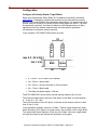
In this example, 872C-D8NP18-E5 sensors are used.
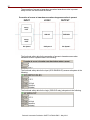
3d
d
Prox
Prox
d
Mark
Space
4d
2d
max. 0.5…0.8 x Sn
min. 3 x Sn
•
d = 18 mm = 872C-D8NP18-E5 diameter
•
2d = 36 mm = Space width
•
3d = 54 mm = sensors mounted on 54 mm centers
•
4d = 72 mm = Mark length
•
The Mark plus Space length = 108 mm
The 872C-D8NP18-E5 sensor has a nominal sensing distance (Sn) of 8 mm.
The maximum distance from the face of the sensor to the ‘Mark’ must be between
4… 6 mm (0.5…0.5 x Sn).
The minimum distance from the ‘Space’ to the face of the sensors must be no less
than 24 mm (3 x Sn).
In this application example, there are 10 ‘Mark’ / ‘Space’ targets around the ‘target
wheel’ providing 10 off signals, from each sensor, per revolution of the ‘target wheel’.
The ‘target wheel’ has a diameter of 344 mm at the ‘Mark’. Mount the ‘target wheel’
as close as possible to the relevant the hazardous moving parts.
Rockwell Automation Publication SAFETY-AT086A-EN-P – May 2013