1
21
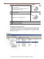
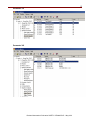
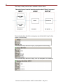
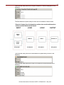
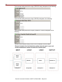
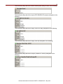
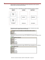
The functional safety data for the Output (PowerFlex 70 drive) subsystem is the
following:
The E-stop data includes Mean Time To Failure, dangerous (MTTFd), average
Diagnostic Coverage (DCavg), and Common Cause Failure (CCF) data. This is
because these are electro-mechanical devices. Electro-mechanical devices
functional safety evaluations include how frequently they are operated, whether they
are effectively monitored for faults and whether they are properly specified and
installed.
This application example presumes that the E-stop is operated twice a day or 730
times per year.
The DCavg (99%) for the E-stop was selected from the Input Device table of EN ISO
13849-1 Annex E, Cross Monitoring.
The CCF value is generated by using the scoring process outlined in Annex F of ISO
13849-1. The complete CCF scoring process must be performed when actually
implementing an application. A minimum score of 65 points must be achieved. A
CCF of 65 was entered for practical purposes in each case for this application
example.
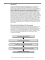
Verification and Validation Plan
Verification and validation play an important role in the avoidance of faults
throughout the safety system design and development process. ISO/EN 13849-2
sets the requirements for verification and validation. It calls for a documented plan to
make sure all of the Safety Functional Requirements have been met.
Verification is an analysis of the resulting safety control system. The Performance
Level (PL) of the safety control system is calculated to make sure it meets the
Required Performance Level (PLr) specified. The SISTEMA software tool is typically
used to perform the calculations and assist with satisfying the requirements of ISO
13849-1.
Validation is a functional test of the safety control system to demonstrate that it
meets the specified requirements of the safety function. The safety control system is
tested to make sure all of the safety related outputs respond appropriately to their
corresponding safety related inputs as intended. Include normal operating conditions
in the functional test. Additionally, certain faults must be ‘injected’, that is, created, to
confirm proper system response to those fault conditions. Testing is typically built
around a checklist used to document the validation of the safety control system.
Prior to validating the Guardmaster Safety Relay (GSR) system, you must confirm
that the GSR Relay has been wired and configured in accordance with the
installation instructions.
Rockwell Automation Publication SAFETY-AT086A-EN-P – May 2013