1
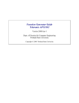
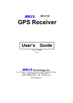
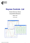
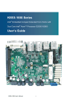
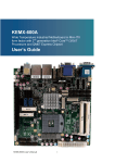
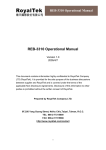
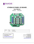
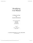
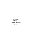
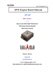
G-Mouse GPS Receiver
GMR75
User Manual
GMR75 GPS Receiver User Manual
Table of Contents
Usage Notice… … … … … … … … … … … … … … … … … … … … … … … … … … … … … … … … … … … .2
0. Quick Start … … … … … … … … … … … … … … … … … … … … … … … … … … … … … … … … … … . 2
0.1 Check the package… … … … … … … … … … … … … … … … … … … … … … … … … … … … … ...2
0.2 Check the connector… … … … … … … … … … … … … … … … … … … … … … … … … … … … … .2
0.3 Connection to your equipment… … … … … … … … … … … … … … … … … … … … … … … … … .2
1. Introduction … … … … … … … … … … … … … … … … … … … … … … … … … … … … … … … … … … 3
1.1 Introduction… … … … … … … … … … … … … … … … … … … … … … … … … … … … … … … … ..3
1.2 Features… … … … … … … … … … … … … … … … … … … … … … … … … … … … … … … … … … 3
1.3 Technical Specification… … … … … … … … … … … … … … … … … … … … … … … … … … … … 4
2. Operational Characteristics… … … … … … … … … … … … … … … … … … … … … … … … … … … 4
2.1 Initialization setup… … … … … … … … … … … … … … … … … … … … … … … … … … … … … … 4
2.2 Navigation… … … … … … … … … … … … … … … … … … … … … … … … … … … … … … … … … 5
3. Hardware Specification… … … … … … … … … … … … … … … … … … … … … … … … … … … … ..5
3.1 Outline… … … … … … … … … … … … … … … … … … … … … … … … … … … … … … … … … … .5
3.2 Connection interface… … … … … … … … … … … … … … … … … … … … … … … … … … … … … 5
3.3 Output connector… … … … … … … … … … … … … … … … … … … … … … … … … … … … … … .6
3.4 Accessories… … … … … … … … … … … … … … … … … … … … … … … … … … … … … … … … ..6
4. GMR75 USB Driver… … … … … … … … … … … … … … … … … … … … … … … … … 7
4.1 System requirement… … … ...… … … … … … … … … … … … … … … … … … … … … … … … … ..7
4.2 Install USB driver… … … … … … … … … … … … … … … … … … … … … … … … … … … … … … 7
4.3 Verify the driver installation… … … … … … … … … … … … … … … … … … … … … … … … … … 8
5. Warranty… … … … … … … … … … … … … … … … … … … … … … … … … … … … … … … … … … … … 8
6. Trouble Shooting Guide… … … … … … … … … … … … … … … … … … … … … … … … … … … … … … 8
6.1 Satellite signal problem… … … … … … … … … … … … … … … … … … … … … … … … … … … … 8
6.2 Position fixing problem… … … … … … … … … … … … … … … … … … … … … … … … … … … … 9
6.3 GPS not fix problems.… … … … … … … … … … … … … … … … … … … … … … … … … … … … 10
6.4 GMR75 driver confliction problem… … … … … … … … … … … … … … … … … … … … … … .10
Appendix A Software Protocol… … … … … … … … … … … … … … … … … … … … … … … … … … … … 11
A.1 NMEA transmited message… … … … … … … … … … … … … … … … … … … … … … … … … ..11
Appendix B Coordinate System and Output Settings… … … … … … … … … … … … … … … … … … … . 14
B.1 Coordinate system… … … … … … … … … … … … … … … … … … … … … … … … … … … … … 15
B.2 Output settings… … … … … … … … … … … … … … … … … … … … … … … … … … … … … … ...15
Appendix C Order Information… … … … … … … … … … … … … … … … … … … … … … … … … … … … 15
C.1 GMR75 packages… … … … … … … … … … … … … … … … … … … … … … … … … … … … … 15
C.2 Accessories… … … … … … … … … … … … … … … … … … … … … … … … … … … … … … … … 15
C.3 Product packages… … … … … … … … … … … … … … … … … … … … … … … … … … … … … ...15
Page 1
GMR75 GPS Receiver User Manual
Usage Notice
Please read before you start to use the GPS receiver:
Ø GPS(Global Position System) is found and operated by US Department of defense. The
Organization is responsible for accuracy and maintenance of the system with full authority. Any
change that is made by the organization will affect accuracy and function of GPS.
Ø For your driving security, we strongly suggest that you do not operate the device during driving.
Ø When satellite is navigating, if you are inside a building, tunnel or near huge blocks, it will affect
GPS satellite signal receiving. At this time, this device probably dose not have positioning
capability.
Ø If you have a speed alarm in your car, the signal receiving of this device will be interfered. If this
situation happens, please stop using your speed alarm.
Ø The receiver operating temperature is located between -10℃~70℃.For safety and lifetime of
Li- ion battery usage, do not place this device over two hours with overheated environment.
0. Quick Start
0.1 Check the package
A. Standard pack
GMR75 (GPS receiver, including magnet pad), disc and quick use manual
B. Optional accessory
To collocate with different kinds of computers and handset devices, GMR75 GPS receivers you
purchase may include different accessories as below:
1. Computer connector
2. Software (navigation or special software)
3. Other software/hardware
0.2 Check the connector
A.PS/2 to USB adapter. Before connecting,
please refer to Chapter 4: Install the driver
from the CD-Rom.
PS/2 to USB
0.3 Connect to your equipment
A. Connect the GMR75 to your equipment
Page 2
GMR75 GPS Receiver User Manual
B. Put GMR75 in a appropriate place to receive the best GPS satellite signal.
C. Turn on your equipment (or switch the handhold device on)
D. Your GMR75 will start to provide you GPS satellite positioning function.
1. Introduction
1.1 Introduction
GMR75 is a total solution GPS receiver (GMR75 instead below), designed based on most high
sensitivity MediaTek kernel architecture. This positioning application meets strict needs such as car
navigation, mapping, surveying, security, agriculture and so on. Only clear view of sky and certain
power supply are necessary to the unit. It communicates with other electronic utilities via compatible
dual-channel through RS-232 or TTL and saves critical satellite data by built–in backup memory. With
low power consumption, the GMR75 tracks up to 32 satellites at a time, re-acquires satellite signals in
1 sec and updates position data every second. 4 power-saving mode allows the unit operates with ultra
low power request.
1.2 Features
GMR75 provides a host of features that make it easy for integration and use.
1. Use the most advantage GPS module (MediaTek), the module got high performance CPU
inside(ARM CPU), allow users to design different applications, store in the module, to provide the
most economic solution for anybody.
2. High performance receiver tracks up to 32 satellites while providing first fast fix and low power
consumption.
3. Compact design ideal for applications with minimal space.
4. A rechargeable battery sustains internal clock and memory. The battery is recharged during normal
operation.
5. Auto switch-able power saving mode 1~4, reduce your power exhaust.
6. User initialization is not required.
7. Dual communication channels and user selectable baud rates allow maximum interface capability
and flexibility.
8. Optional communication levels, RS-232 and TTL meet ordinary application and new fashions of
connecting PDA with TTL or RS -232 output.
9. FLASH based program memory: New software revisions upgradeable through serial interface.
10. Industry level water proof design for all weather.
Page 3
GMR75 GPS Receiver User Manual
1.3 Technical Specification
1.3.1 Dimension
Single construction integrated antenna/receiver.
Size: 60.0 (L) x 54.0 (W) x 27.0 (H) (mm)。
2.36 (L) x 2.13 (W) x 1.06 (H) (Inch)。
1.3.2 Environmental Characteristics
1) Operating tempe rature: -10o C~70oC (internal)。
2) Storage temperature: -40o C ~85o C
1.3.3 Electrical Characteristics
1) Input voltage : +4.75~+5.5V DC
1.3.4 Performance
1) Tracks up to 32 satellites.
2) Update rate: 1Hz.
3) Acquisition time (average)
Hot start: 1 sec
Warm start: 36 sec
Cold start: 37 sec
4) Position accuracy:
A) None DGPS (Differential GPS)
Position: < 3m CEP (50%) without SA (horizontal)
Time: 0.1 ms synchronized GPS time
B) DGPS ( Differential GPS)
Position: <2.5m
5) Dynamic Conditions:
Altitude: 18,000 m (60,000 feet)max
Velocity: 515 m/sec (700 knots)
Acceleration: 4G max
1.3.5 Interfaces
1) Dual channel RS-232 or TTL compatible level, with user selectable baud rate (4800, 9600-Default,
19200, 38400)
2) NMEA 0183 Version 3.01 ASCII output (Default:GGA,GSA,GSV,RMC,VTG,CHN).
2. Operational Characteristics
2.1 Initialization Setup
After the initial self-test is complete, the GMR75 will begin the process of satellite acquisition and
tracking. The acquisition process is fully automatic and, under normal circumstances, will take
approximately 37 seconds to achieve a position fix (36 seconds if ephemeris data is know). After a
position fix has been calculated, valid position and time information will be transmitted over the output
channel(s).
The GMR75 utilizes initial data such as last stored position, data and time as well as satellite
orbital data to achieve maximum acquisition performance. If significant inaccuracy exists in the initial
data, or if the orbital data is obsolete, it may take a long time to achieve a navigation solution. The
GMR75 Auto-locate feature is capable of automatically determining a navigation solution without
intervention from the host system. However, acquisition performance can be improved if the host
system initialized the GMR75 following the occurrence of one or more of the following events:
Page 4
GMR75 GPS Receiver User Manual
1) The GPS receiver is not in use for more than 3 months or transportation over distances further than
500 kilometers.
2) Power off the PDA main power without system standby power.
2.2 Navigation
After the acquisition process is complete, the GMR75 will begin sending valid navigation information
over its output channels. These data include:
1) Latitude/longitude/altitude
2) Velocity
3) Date/time
4) Error estimates
5) Satellite and receiver status
3、Hardware Specification
3.1 Outline
Size: 60.0 (L) x 54.0 (W) x 27.0 (H) (mm)。
2.36 (L) x 2.13 (W) x 1.06 (H) (Inch)。
3.2 Hardware Interface
The GMR75 intelligent satellite receiver, includes GPS receiver and an antenna in a unique style
gadget. Simply connect PS/2 male connector to one of the accessories linking to your notebook PC,
PDA or other devices. Optional color, input voltage and output connector are listed and described
bellow:
GMR75
PS/2 to USB adapter
PS:The picture only supplies the reference, please depend on the actual product.
Page 5
GMR75 GPS Receiver User Manual
3.3 Output Connector
Cable length: 2 meter, Connector: PS/2 female.
Function definition of PS-2 female composite connectors.
5
6
4
Pin
1
2
3
4
5
6
1
3
2
Signal
RS-232+TTL
TX(RS232)
+5V DC
Tx(TTL)
Ground
Rx(TTL)
RX(RS232)
RS-232
Tx
+5V DC
NC
Ground
DGPS in
Rx
3.4 Accessories
In order to connect with different system, we provides several kinds of connectors to choose as
following:
3.4.1 PS/2 connector definition:
Pin Signal Name
1
+5V
2,3,5,6
N.C
4
Ground
N.C. :Not connection
6
5
1
4
2
3
3.4.2 USB connector
The
Pin
1
2
3
4
4
USB type:A type
Signal Name
+5V
D+
DGround
1
3.4.3 Magnetic plate (Concurrently fixed stand)
The magnetic plate, a standard equipment, has been put in the GMR75 base on delivery, can be
put on the car roof, the boat roof or the other brace and face to the sky.
4、GMR75 USB Adapter Driver
4.1 System requirement
PC: IBM, Pentium or above or compatible PC。
Memory: 16MB or above。
Operation system: Windows 98/Me/2000/2000XP
Display card: VGA compatible.
Page 6
GMR75 GPS Receiver User Manual
4.2 Install USB Driver
1) Insert the CD-ROM: [GPS Driver&Manual]
into the CD drive. Please make sure that the
auto-play function is enabled!
2) Please follow the screen guide and click
[Install/Remove GMR75 Device Driver]
3) Please follow the screen to install the USB
driver. Maybe it is necessary to reboot PC,
please reboot as it says.
4) Insert the GMR75 USB connector into any
empty USB slot, now your PC will
recognize the USB device automatically.
You may use the GMR75 freely now.
4.3 Verify the Driver Installation
Please identify the COM port ID after you install the GMR75 USB driver:
1) Click [Start], [Setup], and click the [Control Panel].
Page 7
GMR75 GPS Receiver User Manual
2) While the windows of [Control Panel] shows up,
double click the [System], [Hardware] and click the
button [Device Manager]. Expend the tree node
[Ports(COM&LPT)], you should see the item
[Prolific USB-to Serial Comm Port (COM#) ]. If so,
it means you can use GMR75 correctly now.
3) The “#” mark means the COM port ID simulated by
the USB adapter. Most of the GPS navigate software
use COM1 as default settings. You should change it
to the corresponding port ID mapped by the USB
adapter, and GMR75 can report GPS message
correctly.
5. Warranty
The GMR75 is warranted to be free from defect in materials and functions for one year from the
date of purchase. Any failure of this product within the period under normal conditions will be replaced
at no charge to the customers.
This warranty does not cover failures due to abuse, misuse, accident, or unauthorized alteration or
repairs, inappropriate disassemble.
6. Trouble Shooting Guide
6.1 Satellite Signal Problem
It is normal if you found that the GPS satellite signal very low or absolute missing:
Ø
While you are in a tunnel, GPS signal isolated.
Ø
There is something cover above, GPS signal isolated.
Page 8
GMR75 GPS Receiver User Manual
n
n
Ø
Inside of the building, GPS signal isolated.
Ø
Buildings near by, GPS signal interfered.
Ø
Inside the forest, lots of covers above, GPS signal level down.
If you use GMR75 inside the car, some sun-control film will makes the GPS signal low or
lost.
GPS satellite is owned by America army, sometimes they will tune -down the accuracy by
some reason. In such cases, the GPS position may not fixed exactly.
6.2 Position Fixing Problem
The position fix problem below does not mean the GMR75 GPS receiver’s malfunction:
Ø
You are driving on the freeway, but the GPS navigation
software shows you are on the road beside. Or the opposite
situation.
Ø
You are driving on a grid like lane, it is possible to show
your car on an incorrect lane, if these 2 lane very near.
Ø
If you translate the GPS receiver inside somewhere with no
satellite signal, the GPS position may stay at the position
before.
Page 9
GMR75 GPS Receiver User Manual
6.3 GPS Not Fix Problems
If you see [GPS not Fix] message on the screen after you enable the GMR75 GPS receiver, please
consider the possibility below:
n Please wait few minutes more. GPS position fix may cost several minutes.
n Please make sure that you put the GMR75 GPS receiver at a proper place. Some sun-control
film for car may cutoff the satellite signal. You may replace it and try again.
Please make sure that you are not inside of somewhere the GPS signal shaded. Please reference the
chapter [Satellite Signal Problem] about this.
6.4 GMR75 Driver Confliction Problem
If you notice that the PC’s mouse cursor is in panic, or you just can’t find GPS device in your GPS
navigation software, please follow the steps below to check:
1) Please disconnect the GMR75 and the adapter
in your package, but leave the adapter
connected to your USB slot.
2) Click [Start], [Se tup], and click the [Control
Panel].
3) After the window of [Control Panel] shows up,
double click [System], [Hardware], and click
[Device Manager]. Expand the tree node [Ports
(COM & LPT)], see if something like
[Microsoft Serial BallPoint] or [Microsoft
Serial Mouse] there.
4) Right click on it and select [Disable].
5) Re-connect the GMR75 and your accessory, the
GMR75 will back to work normally now.
Page 10
GMR75 GPS Receiver User Manual
Appendix A Software Protocol
The protocol of GMR75 is designed base on NMEA (National Marine Electronics Association)
0183 ASCII format. The full protocol is defined in “NMEA 0183, Version 3.01”.
A.1、NMEA Transmitted Message
GMR75 GPS receiver use MediaTek as the core, and output NMEA-0183 standard format
message. The default communication parameters for NMEA output are 9600 baud, 8 data bits, stop bit,
and no parity.
Table A-1 NMEA-0183 Output Messages
NMEA Sentence
Description
GPGGA
Global positioning system fixed data
GPGLL
Geographic position latitude \ longitude
GPGSA
GNSS DOP and active satellites
GPGSV
GNSS satellites in view
GPRMC
Recommended minimum specific GNSS data
GPVTG
Course over g round and ground speed
GPZDA
Data and Time
A.1.1 Global Positioning System Fix Data (GGA)
Samples:
$GPGGA,161229.487,3723.2475,N,12158.3416,W,1,07,1.0,9.0,M, , , ,0000*18
Table A-2 GGA Data Format
Name
Description Units
Description
Message ID
$GPGGA
GGA protocol header
UTC Time
161229.487
Hhmmss.sss
Latitude
3723.2475
ddmm.mmmm
N/S Indicator
N
N = north or S = south
Longitude
12158.3416
dddmm.mmmm
E/W Indicator
W
E = east or W = west
Position Fix Indicator
1
See Table4-3
Satellites Used
07
Range 0 to 12
HDOP
1.0
Horizontal Dilution of Precision
MSL Altitude
9.0
Meters
Units
M
Meters
Geoid Separation
Meters
Units
M
Meters
Age of Diff. Corr.
Second Null fields when DGPS is not used
Diff. Ref. Station ID
0000
Checksum
*18
Table A-3 Position Fix Indicator
Value
Description
0
0 Fix not available or invalid
1
GPS SPS Mode fix valid
Page 11
GMR75 GPS Receiver User Manual
Value
Description
2
Differential GPS, SPS Mode fix valid
3
GPS PPS Mode fix valid
A.1.2 Geographic Position - Latitude/Longitude (GLL)
Samples:
$GPGLL,3723.2475,N,12158.3416,W,161229.487,A*2C
Table 1-4 GLL Data Format
Name
Example Units Description
Message ID
$GPGLL
GLL protocol header
Latitude
3723.2475
dd mm.mmmm
N/S Indicator
N
N = north or S = south
Longitude
12158.3416
ddd mm.mmmm
E/W Indicator W
E = east or W = west
UTC Position
161229.487
hh mm ss.sss
Status
A
A = data valid or V = data not valid
Checksum
*2C
A.1.3 GNSS DOP and Active Satellites (GSA)
Samples:
$GPGSA,A,3,07,02,26,27,09,04,15, , , , , ,1.8,1.0,1.5*33
Table A-5 GSA Data Format
Name
Example Units
Description
Message ID
$GPGSA
GSA protocol header
Mode 1
A
See Table 4-6
Mode 2
3
See Table 4-7
Satellite Used *1 07
SV on Channel 1
Satellite Used *1
SV on Channel 2
… ..
… ...
Satellite Used *1
SV on Channel N
PDOP
1.8
Position Dilution of Precision
HDOP
1.0
Horizontal Dilution of Precision
VDOP
1.5
Vertical Dilution of Precision
Checksum
*33
*1 Satellite used in solution.
Table A-6 Mode 1
Value
Description
M
Manual – forced to operate in 2D or 3D mode
3
Automatic – allowed to automatically switch 2D/3D
Table A-6 Mode 2
Value
1
Fix Not Available
2
2D
3
3D
Description
A.1.4 GNSS Satellites In View (GSV)
Page 12
GMR75 GPS Receiver User Manual
Samples:
$GPGSV,2,1,07,07,79,048,42,02,51,062,43,26,36,256,42,27,27,138,42*71
$GPGSV,2,2,07,09,23,313,42,04,19,159,41,15,12,041,42*41
Table A-8 GSV Data Format
Name
Example Units
Description
Message ID
$GPGSV
GSV protocol header
Number of
2
Range 1 to 3
Messages1
Message Number 1 1
Range 1 to 3
Satellites in View 07
Range 1 to 12
Satellite ID
07
Channel 1 (Range 1 to 32)
Elevation
79
degrees Channel 1 (Maximum 90)
Azimuth
048
degrees Channel 1 (True, Range 0 to 359)
SNR (C/No)
42
dBHz Range 0 to 99, null when not tracking
… ..
… …
Satellite ID
27
Channel 4 (Range 1 to 32)
Elevation
27
degrees Channel 4 (Maximum 90)
Azimuth
138
degrees Channel 4 (True, Range 0 to 359)
SNR (C/No)
42
dBHz Range 0 to 99, null when not tracking
Checksum
*71
NOTE: Item <4>,<5>,<6> and <7> repeat for each satellite in view to a maximum of four (4)
satellite per sentence. Additional satellites in view information must be sent in sentences. These
fields will be null if unused.
A.1.5 Recommended Minimum Specific GNSS Data (RMC)
Samples:
$GPRMC,161229.487,A,3723.2475,N,12158.3416,W,0.13,309.62,120598, ,*10
Table A-9 RMC Data Format
Name
Message ID
UTC Position
Status
Latitude
N/S Indicator
Longitude
E/W Indicator
Speed Over Ground
Course Over Ground
Date
Magnetic Variation1
E/W Indicator
Checksum
Example
Units
$GPRMC
161229.487
A
3723.2475
N
12158.3416
W
0.13
knots
309.62
degrees
120598
02.6
degrees
W
*10
A.1.6 Course Over Ground and Ground Speed (VTG)
Samples:
$GPVTG,309.62,T, ,M,0.13,N,0.2,K*6E
Table A-10 VTG Data Format
Name
Example
Unit
Page 13
Description
RMC protocol header
Hh mm ss.sss
A = data valid or V = data not valid
dd mm.mmmm
N = north or S = south
ddd mm.mmmm
E = east or W = west
True
dd mm yy
E = east or W = west
Description
GMR75 GPS Receiver User Manual
Message ID $GPVTG
VTG protocol header
Course
309.62
Degrees Measured heading
Reference
T
Course
Degrees Measured heading
Reference
M
Magnetic *1
Speed
0.13
Knots
Measured horizontal speed
Units
N
Speed
0.2
Km/hr Measured horizontal speed
Units
K
Kilometer per hour
Checksum
*6E
Note *1 :All "course over ground" data are geodetic WGS84.
A.1.7 Time & Date (ZDA)
Samples:
$GPZDA,114523.62,12,04,2001,10,34*6E
Table 1-11 ZDA Data Format
Name
Example Units
Message ID
$GPZDA
Hour, Min, Sec, Sub Sec 114523.62
Day
12
Month
4
Year
2001
Local Zone Hours
10
Local Zone Minutes
34
Checksum
*6E
Description
ZDA protocol header
Hhmmss.ss
day in UTC, 01 to 31
month in UTC, 01 to 12
year in UTC
local zone hours, +/- 13 hours
local zone minutes, 0 to +59
Appendix B Coordinate System and Output Settings
B.1 Coordinate System
World standard coordinate system WGS84 is builds in.
B.2 Output Settings
Coordinate System: WGS84。
Baud rate: 9600
Output message: GGA, GSA, GSV, RMC, VTG,CHN
Page 14