1
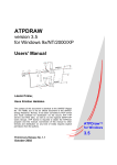
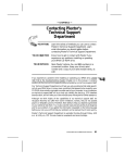
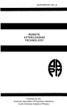
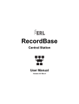
APPLICATION NOTE
L-PRO Line Protection Relay
Improving the Operation of Multi-Breaker Transmission Terminals
Introduction
The advent of multi-function numerical protection relays
has done much to improve the protection of transmission
terminals by increasing dependability and security of distance protection. In addition, multi-function relays improve
operations by increasing the reliability of the control system by decreasing the number of discrete devices, and
thereby decreasing the number of points of failure. While
almost all numerical protection relays include auxiliary protection functions like automatic reclosing, synchronism
check, and breaker failure functions, many are designed
with only one set of current inputs, limiting the application
of these auxiliary functions to single breaker transmission
terminals. For the ring bus and breaker-and-a-half multibreaker schemes that are commonly used in North
America, separate discrete devices are still required for
these specific auxiliary functions. Also, the large number
of electro-mechanical transmission protection systems in
service obviously require separate discrete devices for
these specific auxiliary functions.
This application note describes how the L-PRO Line
Protection Relay from ERLPhase, using multiple sets of
current and voltage inputs, improves the operation of ring
bus and breaker-and-a-half transmission terminals by
using one device to provide the automatic reclosing, synchronism check and breaker failure protection functions
for both circuit breakers. This application can reduce the
number of wires required for a multi-breaker line terminal
by 50% over traditional solutions. The approach greatly
improves control system reliability by reducing engineering, wiring, and testing complexity, and by reducing the
number of devices and connections to fail, with the added
benefit of reduced capital costs for installation.
Current Practices
Networked transmission systems in North America typically use ring bus or breaker-and-a-half transmission terminals. This arrangement provides high reliability of the
transmission system, the ability to maintain individual circuit breakers without line outages, and (in the case of
breaker-and-a-half terminals) the ability to maintain buses
without outages. This practice leads to complexity in the
protection of transmission lines, particularly in terms of
auxiliary protection functions, such as automatic reclosing,
synchronism check, and breaker failure. Figure 1 is a simplified schematic of a breaker-and-a-half protection
scheme.
50BF
-1
25-1
25-2
52-1
79-2
50BF
-2
52-2
67N
21N
21
Figure 1: Simplified breaker-and-a-half protection scheme.
Primary Line Protection Practices
The common practice for primary line protection of an individual transmission line on ring bus or breaker-and-a-half
transmission terminals is to electrically sum the currents
from both circuit breakers, by physically connecting the CT
leads. This method directly measures all current flowing
into or out of the transmission line itself. Transmission line
voltages are measured from voltage transformers directly
connected to the transmission line.
Breaker Failure
The breaker failure function is performed by directly measuring the current flowing through an individual circuit
breaker, after a trip command is issued to the circuit
breaker. This requires the breaker failure relay to be able
to identify the specific current flowing through each breaker of a ring bus or breaker-and-a-half scheme. Multibreaker transmission line protection relays that electrically
sum the currents from both breakers can therefore not be
used, requiring a separate breaker failure relay for each
breaker.
Product specifications and information contained herein are subject to change without notice.
© 2008, ERLPhase Power Technologies. All rights reserved. (D02379R00).
79-1
Tel: 204-477-0591
Fax: 204-478-1697
www.erlphase.com
[email protected]
Automatic Reclosing
New Application
When automatic reclosing is used on a multi-breaker transmission
terminal, both circuit breakers require a close signal after an operation. Some operating philosophies permit automatic reclosing of
both circuit breakers. Other operating philosophies permit automatic reclosing of only one circuit breaker and require manual reclosing of the other breaker. In either case, one circuit breaker must be
identified as the lead breaker to reclose (or the main circuit breaker
for the line) and the other as the follower (or auxiliary) circuit breaker to reclose. The complexity comes from correctly identifying the
lead and follower circuit breakers in all operating situations, including various system operating contingencies, and during breaker
maintenance activities.
For electro-mechanical protection systems, it is customary to have
separate reclosing relays for each circuit breaker. With multi-function numerical protection systems, as illustrated in Figure 2, the
reclosing function from one relay is typically used for both circuit
breakers.
Employing multi-function numerical protection relays with multiple
sets of CT and VT analog signal inputs improves the operations of
multi-breaker transmission terminals by reducing the number of
discrete devices required, reducing the amount of wiring required
for correct operation, simplifying the operation of the line terminal,
and providing flexibility in operations. The L-PRO Line Protection
Relay is a distance relay designed for complete protection and
operation of a multi-breaker line terminal. In addition to the traditional line protection functions, the L-PRO offers multiple sets of CT
and VT inputs to provide the auxiliary protection functions of breaker failure, synchronism check, and automatic reclosing for both
breakers. This basic application is shown in Figure 3.
50BF
-1
52-1
50BF
-2
25-1
52-1
52-2
67N
50BF
-1
50BF
-2
21N
79-1
79-2
21
25-1
25-2
L-PRO
Line Protection
Relay
52-2
Figure 3: L-PRO multi-breaker application.
67N
21N
79
21
25-2
To apply the L-PRO in multi-breaker line terminal applications,
there is an explicit setting called “Ring Bus”. This setting enables
reclosing and breaker failure for both circuit breakers. In ERLPhase
relays, these breakers are identified as the “Main” and “Auxiliary”
breakers.
Breaker Failure – There is a separate breaker failure element for
both the Main and Auxiliary circuit breakers in the L-PRO relay. The
breaker failure elements are traditional 2-stage breaker failure elements, initiated by an internal protection function trip or by an
external signal. The breaker position is determined by flow of current through the breaker.
Automatic Reclosing in the L-PRO – Automatic reclosing is applied
by settings, individual to each of the L-PRO’s 8 settings groups. Up
to 4 reclosing shots are available, initiated by an internal protection
function trip, or by an external signal. The L-PRO automatic reclosing function is specifically designed for application on multi-breaker
line terminals, as shown by the reclosing element settings in Figure
7. The lead circuit breaker for reclosing is user-selectable (Main
breaker then Auxiliary breaker, Main breaker only, Auxiliary breaker
only, or Auxiliary breaker then Main breaker). Reclosing times are
user-selectable for each lead breaker attempt. The follower breaker
will reclose on each attempt after a follower timer expires, or will
only reclose when the lead breaker reset timer expires (indicating a
successful reclose).
Figure 2: Multi-function numerical breaker-and-a-half protection scheme.
Synchronism Check
Closing a circuit breaker on a networked transmission system typically requires a synchronism check to ensure different sources are
connected together only during synchronous conditions to prevent
equipment damage. A synchronism check must be performed
before closing either circuit breaker for the transmission line, as
both circuit breakers may be connected to different sources.
Electro-mechanical systems require a separate synchronism check
relay for each circuit breaker, or a synchronism check relay
designed for multiple sources. Multi-function numerical systems
also typically require a separate synchronism check relay for each
breaker, one typically included as a function in the line protection
device, and one as an additional discrete device.
Traditional electro-mechanical protection systems for multi-breaker
terminals (beyond the line protection itself) must provide 6 additional relays to provide reclosing, synchronism check, and breaker failure for both circuit breakers. These systems also introduce accompanying engineering design time, drafting time, extra wiring, and
increasing points of failure. Multi-function numerical protection
schemes (beyond the line protection itself) must provide at least 3
additional relays for reclosing, synchronism check, and breaker failure. The control logic to identify the main & auxiliary breaker, to
change between the main and auxiliary breaker, and to account for
one breaker being out of service, is typically a hard-wired control
logic involving control switches and auxiliary relays. This logic is
difficult to design, install, and test.
2
Tel: 204-477-0591
Fax: 204-478-1697
www.erlphase.com
[email protected]
Operations Improvement. The most complicated operational procedure for a multi-breaker line terminal where reclosing is applied, is
to take one of the circuit breakers out of service for maintenance
purposes. By using the L-PRO relay, the process of re-establishing
which breaker is the main circuit breaker and blocking reclosing for
the out-of-service breaker, becomes simply a matter of changing
settings groups, either by SCADA command or local control.
Figure 4: L-PRO Recloser settings.
L-PRO
To change the reclosing sequence, or to only reclose one circuit
breaker when the other circuit breaker is out of service, requires
only a settings group change.
Synchronism Check in the L-PRO – The L-PRO’s synchronism
check function compares voltage between the line VTs and auxiliary bus VTs. The auxiliary bus VTs may be one single-phase VT or
a three-phase set of VTs. The synchronism check function in the LPRO can perform any combination of synchronism check, dead
main-live auxiliary, live main-dead auxiliary, or dead main-dead
auxiliary. Automatic reclosing only explicitly uses synchronism
check on lead breaker reclosing attempts. To check synchronism
when reclosing the follower breaker, use ProLogic equations to
supervise the 79 Aux Reclose command, and a combination of
ProLogic equations and output contact to swap between sets of the
auxiliary bus VTs (as described in a separate Technical Note).
On the operations side, the P-PRO improves normal line terminal
operations, reliability, maintenance activities, testing, and system
upgrades. Specifically:
Fewer Devices and Wiring to Fail. By reducing the number of
devices, reliability is increased (as there are fewer devices that can
fail). While the failure of multi-function device will have a greater
impact than the failure of a discrete device, the affected functions
are auxiliary functions, where a failure doesn’t directly impact the
primary protection of the line. Having fewer devices also reduces
the wiring for a terminal. Every wiring termination is a potential
point of failure, so reducing the amount of wiring increases reliability. Applying an L-PRO in this application can reduce the amount of
wiring by 80% over electro-mechanical schemes, and by 50% over
traditional numerical protection and control schemes.
Simpler Line Terminal Control Scheme. Implemented in IED
Software. The traditional multi-breaker line terminal control scheme
is implemented in the settings and logic of the L-PRO relay. This
eliminates the need for complicated, hard-wired control designs,
auxiliary relays, and timers.
Easier to Test. Control schemes, especially where automatic
reclosing is involved, become easier to test. Since the logic is
implemented in relay settings and software, the correct operation of
the scheme can be tested in a laboratory environment, before actual field implementation.
Tested Schemes Can be Replicated at No Effort. The real benefit
of performing control logic in software is replication. A tested,
proven control scheme can be implemented at a different location
simply by downloading the logic and settings into a new relay. This
ensures reliability and consistency of design, simplifies testing
commissioning, and training, and ensures correct operation.
Simpler Field Changes to Control Schemes. By implementing control logic in numerical relays, changes to the logic become simply a
matter of re-programming the relays in the field. This eliminates the
need for physical wiring changes, and the attendant engineering,
drafting, and purchasing efforts.
52-1
Trip
52-2
Clos e
T rip
Cl ose
L-PRO
L-PRO
F-PRO
Line
52-1
Trip
52-2
Clos e
T rip
Settings
Group
SG 2
S G1
43R
On
O ff
Cl ose
52-1
Trip
52-2
Clos e
T rip
Settings
Group
SG 3
SG 2
S G4
S G1
43 L/R
Loc al
R em ote
43R
On
O ff
Cl ose
Settings
Group
SG 3
SG 2
S G4
S G1
43 L/R
Loc al
R em ote
43R
On
O ff
SG 3
S G4
43 L/R
Loc al
R em ote
Figure 5: L-PRO typical panel layout.
The use of one device to perform all protection functions, or auxiliary protection functions, doesn’t impact clear and understandable
operations practices for substation personnel. For example, a typical panel layout for this scheme will be similar to Figure 9, and
includes separate breaker control switches and breaker status
lights for each breaker.
Application Example
Figure 5 shows the basic functionality of a typical application of the
L-PRO for primary line protection and line terminal auxiliary protection functions. This application includes phase distance protection,
ground distance protection, and directional ground overcurrent protection for the transmission line. The L-PRO provides breaker failure protection for both the 52-1 and 52-2 breakers, and provides
automatic reclosing and synchronism check for both breakers.
This application is described more completely by the Figure 10 AC
schematic and the Figure 12 DC schematic. The AC schematic
shows complete analog wiring for this L-PRO application, with separate CT inputs from the 52-1 and 52-2 breakers, and dedicated
inputs for the line VTs.
The L-PRO can perform synchronism check with a single-phase or
three-phase auxiliary voltage. When using a single-phase auxiliary
voltage, the L-PRO automatically determines which phase is connected to perform synchronism check. The other auxiliary voltage
inputs must be grounded. For a single-phase application on multibreaker line terminals, it is necessary to use output contacts and
ProLogic equations to select the appropriate synchronism VT to
connect to the auxiliary VT input on the L-PRO. This logic is
3
Tel: 204-477-0591
Fax: 204-478-1697
www.erlphase.com
[email protected]
described in detail in a separate Technical Note, with a basic concept of keeping the lead breaker synchronism source connected,
then changing to the follower breaker synchronism source after the
lead breaker closes.
The DC schematic shows this application’s basic control scheme.
Manual breaker close commands are issued by the relay to ensure
the proper synchronism source is used, to interface correctly with
the local/remote control conditions, and to simplify wiring. The
scheme uses a selector switch connected to 2 digital inputs to
change the settings group for different operating conditions (based
on the logic in Table 1). The 52-a contact from both circuit breakers
determines breaker position for the automatic reclosing and synchronism check functions.
Normal Operations
Normal system operations is defined, in part, as both circuit breakers in service, with automatic reclosing and synchronism check for
both breakers. For normal system operation, Settings Group 1 is
active and contains the protection settings, and control logic, for
the typical system conditions. Breaker 52-1 of Figure 5 is the Main
breaker, and Breaker 52-2 is the Auxiliary breaker. Reclosing is set
to “Main then Aux”, to reclose first 52-1, then 52-2 after a time
delay.
Auxiliary Breaker Out of Service
When Breaker 52-2 is taken out of service for maintenance, the LPRO relay is switched to Settings Group 2 by use of the settings
group selector switch, or by SCADA command, to adapt the relay
protection and control scheme operate for this condition. Reclosing
is set to “Main Only”, with synchronism check only performed from
the Bus A synchronism source. A note on protection settings: it
may be necessary to adapt the distance protection settings if having one of the line breakers significantly changes system source
conditions.
Table 1: Setting Group selector logic.
EI4
L
L
H
H
Setting Group
1
2
3
4
Operating Conditions
Normal Operations
Aux Breaker Out
Main Breaker Out
Change Lead and Follower
Main Breaker Out of Service
When Breaker 52-1 is taken out of service for maintenance, the LPRO relay is switched to Settings Group 3 by use of the settings
group selector switch, or by SCADA command. Just as when the
52-2 breaker is out of service, this settings group ensures the relay
protection and control scheme operates correctly for when the 52-1
breaker is out of service. Reclosing is set to “Aux Only”, with synchronism check only performed from the Bus B synchronism
source. The same concern about distance protection settings
applies as when the 52-2 breaker is out of service.
(Settings Groups 5-8 not used)
Bus A
Aφ
Main Breaker
Auxiliary Breaker
52-1
52-2
Aφ
Bφ
Cφ
Bφ
Cφ
Bus A
Synch VT
Bus B
Synch VT
Protected Line
Line VTs
IA 1 IA 1 IB 1 IB 1 IC 1 IC 1
300
301
302
303
Main AC
Line Currents
304
305
VA
324
VB
VC
N
325
326
327
Auxiliary
AC Volts
224
226
Out12
225
Out13
227
Swap
Synch VT
Figure 6: L-PRO Line Protection Relay: typical AC schematic.
4
VA
VB
VC
N
330
331
332
333
Main
AC Volts
IA 2 IA 2 IB 2 IB 2 IC 2 IC 2
306
307
308
309
Auxiliary AC
Line Currents
310
311
Bus B
EI3
L
H
L
H
Tel: 204-477-0591
Fax: 204-478-1697
www.erlphase.com
[email protected]
Change Lead and Follower Breaker
There may be operating conditions where it is desirable to change
which breaker is the lead breaker and which breaker is the follower
breaker (for automatic reclosing). In this L-PRO application, this is
simply a matter of changing the relay to Settings Group 4 using the
settings group selector switch. The reclosing is set to “Aux Then
Main”.
Main Bkr
Aux Bkr
01
T
01
T
Main Bkr
52-a
Aux Bkr
52-a
43CS
79B
43CS
L/R
Main Bkr
Aux Bkr
01
C
01
C
202
Out1
203
Main
Bkr
204
206
Out2
207
Aux
Bkr
CC
TC-1
210
Out4
TC-2
-
+
102
+
2
101
-
104
+
3
103
-
106
+
4
105
-
108
+
5
107
-
110
+
6
109
-
112
+
7
111
-
Close Aux Bkr
Close Main Bkr
Local / Remote
Block 79
Select Settings
Group
Aux Bkr Closed
Main Bkr Closed
100
1
114
+
8
113
-
116
9
115
-
117
Out6
213
211
Main
Bkr
CC
+
212
Out5
209
Aux
Bkr
Aux Bkr BF Stage 2 Trip
Main Bkr BF Stage 2 Trip
208
Out3
205
Main
Bkr
TC-1
Close Aux Bkr
Primary Trip Aux Bkr
Close Main Bkr
Primary Trip Main Bkr
Selector Switch
L-PRO Relay
Aux
Bkr
TC-2
Figure 7: L-PRO Line Protection Relay: typical DC schematic.
Other Benefits
52-1
Beyond the improvement of reliability and simplification of the control schemes, there are additional benefits to using the L-PRO Line
Protection Relay to perform the auxiliary protection functions for
multi-breaker line terminals. The first of these is true Digital Fault
Recorder (DFR) quality waveform recording, at 96 samples per
cycle, to capture separate waveforms for both the main and auxiliary circuit breakers. This becomes a simple and low cost way to
add true disturbance recording when upgrading line terminals.
Recording at 96 samples per cycle allows the L-PRO to capture CT
saturation, DC offset, and true peak fault currents (necessary information to provide analysis of unusual fault events). The L-PRO
also has 2 additional sets of current inputs, used to trigger fault
recording based on the operation of other lines or buses, and
includes low-speed swing recording, sampling at 1 sample per
cycle (to provide recording of power swings and similar system
events).
This application note discusses the use of the L-PRO Line
Protection Relay to perform both traditional line protection functions, as well as the auxiliary protection functions for the line terminal. However, typical protection practices for transmission lines use
2 sets of line protection to provide redundancy of protection. The LPRO is designed to meet this practice. Considering numerical line
protection exclusively, the L-PRO provides the primary or redundant line protection, as well as the auxiliary protection functions. As
shown in Figure 14, this reduces the number of discrete relays for
a line terminal to just 2 devices, and easily supports the use of primary and redundant relays that use different operating principles.
52-2
L-PRO
Line Protection Relay
Line
Protection
Relay
67N
67N
50BF
-1
50BF
-2
21N
21N
79-1
79-2
21
21
25-1
25-2
Figure 8: L-PRO Line Protection Relay: typical DC schematic.
IEDs with multiple sets of current and voltage inputs are ideally
designed for future digital substation. The IEC 61850 and IEC
60044 digital communications standards for substations include
provisions for communications between current and voltage transducers and IEDs (current and voltage values digitized at the
source) and communicated to appropriate IEDs. Therefore, electrically summing the input currents for multi-breaker terminals is no
longer possible. These currents must be mathematically summed
in the IED algorithm. Relays with multiple current and voltage
inputs, like the L-PRO, are already designed to meet this new
requirement.
5
Tel: 204-477-0591
Fax: 204-478-1697
www.erlphase.com
[email protected]
Conclusions
References
This application note has shown the L-PRO Line Protection Relay’s
ability to simply provide breaker failure, automatic reclosing, and
synchronism check for both circuit breakers of multi-breaker line
terminals. This application greatly improves the operations of these
terminals through simpler control schemes, and improved reliability
due to fewer devices and less wiring.
Operations and reliability improvements come from both hardware
changes to the protection and controls scheme, and the resulting
simplified control scheme logic. The most obvious of these
changes is the reduction in the amount of wiring required (as great
as a 50% reduction in wires over traditional control schemes). CT
and VT leads, breaker status indications, and control outputs are
only connected to a single device. Using fewer wires simplifies
control circuit design (reducing the possibility for both design and
installation mistakes). It also reduces the number of points of failure in the protection and control system. Reducing the number of
devices also reduces the likelihood of a device failure.
There are also 2 significant cost savings to be gained by combining
auxiliary relay function into one IED. The obvious one is a reduced
capital cost, by eliminating discrete relays required for auxiliary protection functions. This is especially true when using the L-PRO,
since reclosing, synchronism check and breaker failure protection
for both circuit breakers are combined with line protection functions
found in the relay.
The other significant cost saving is due to reducing the amount of
wiring involved. Consolidating several auxiliary devices into one
IED means that CT leads, VT leads, and control inputs need only
be run to one location. This reduces the number of wires, amount
of wire, and time spent wiring and testing, as well as the amount of
time spent designing and drafting the control scheme.
Selecting whether to apply the L-PRO to perform the auxiliary protection functions depends on the specific application, and operating
philosophy, of the utility. A general recommendation for new line
terminals, or for complete upgrade of existing line terminals, is to
use the L-PRO to take advantage of the total protection offering.
However, a utility may desire to keep auxiliary protection functions
separate from primary line protection. For multi-breaker terminals,
it still makes sense to use separate CT leads from each circuit
breaker to the L-PRO, to provide waveform capture for both circuit
breakers during fault events and dynamic swing events.
[1] L. L. Grigsby, Editor, The Electric Power Engineering
Handbook, CRC Press LLC, Boca Raton, FL; 2001.
[2] IEEE PC37.104, Guide for Automatic Reclosing of Line Circuit
Breakers for AC Transmission & Distribution Lines, Institute of
Electrical and Electronics Engineers, Inc., New York, NY; 2003.
[3] L-PRO Line Protection Relay User Manual Version 3.2 Revision
1, ERLPhase Corporation, Winnipeg, MB, Canada; 2002
[4] IEEE Std. C37.113-1999 Guide for Protective Relay Applications
to Transmission Lines, Institute of Electrical and Electronics
Engineers, Inc., New York, NY; 2000.
List of Symbols
52
21
Inverter Logic Gate
Current Transformer
AND Logic Gate
Circuit Breaker
T
Control Logic
TC-1
Circuit Breaker Trip Coil
Phase Distance Protection
CC
Circuit Breaker Close Coil
0
Timer Logic Element
21N
Ground Distance Protection
Fuse
67N
Directional Ground
Overcurrent Protection
Control Contact
25
Synchronism Check
Relay Output Contact
79
Automatic Reclosing
50BF
6
Voltage Transformer
Breaker Failure Protection
1
Relay Digital Input