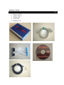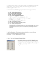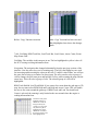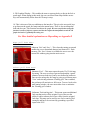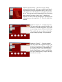
1
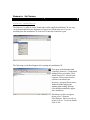
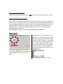
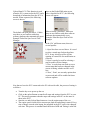
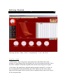
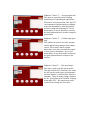
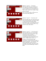
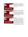
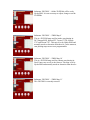
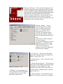
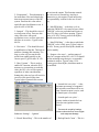
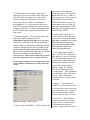
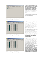
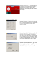
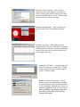
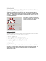
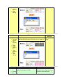
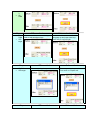
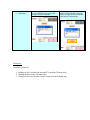
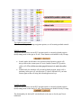
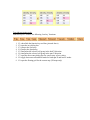
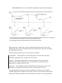
Software Version: 2.X • • • • • • • • Nemesis 2.17 User Manual 31st Dec 2005 For Racing and Off-Road Use Only Not Legal on Public Highways and or Emission Controlled Vehicles unless Appropriately Certified The information in this document is subjected to change without notice. As every effort is taken to ensure the correctness of the manual, no responsibilities will be taken for the consequences of any omissions and or inaccuracies in this manual. The manufacturer and its agents accept no responsibility for personal injury and or property damage from the use of the products. Hydra EMS systems offer extreme amount of user adjustability, installation and tuning must be performed by a qualified professional If you install the unit yourself, be aware of the following points: o Fuel Injection systems use a high-pressure Fuel Supply. Extreme Care should be taken to avoid fire when work on the fuel system is performed. o High-energy ignition systems produce dangerous voltages. Never touch or remove any ignition system component when the battery is connected, even if the car is not running. o The driver should never attempt to tune the vehicle while it is in motion. We recommend that the vehicle be tuned on a dynamometer. o Severe engine damage can result from lean out (too high an air fuel ratio) or over advanced ignition timing. Have the vehicle tuned by a professional if you are not sure of what values to use for high load air fuel ratio and ignition angle specific to your car. All Hydra EMS products are covered by a 12 month warranty period as detailed below: o Warranty extends only to the repair or replacement of the product and only within the warranty period. o The product is only warranted against defective materials and or workmanship and only on condition that a qualified mechanic and or an engine management professional installed the product in accordance with the manufacturer’s instructions. o Warranty period starts from the date of installation or thirty days from the date of purchase; whichever is sooner o Warranty is void if the product is in any way dismantled, tapered with, improperly installed and or modified to fit an application not listed in the manufacturer applications list. o Warranty does not cover, but is not limited to, the following: Injury to person or persons Towing cost Lost of use Accommodation and lost of income Labor charges Consequential damage Engine backfire/misfire damage Engine detonation damage Damage from accidents Floods, earthquakes, or any acts of god Physical shock Misuse Negligent handling of product Water damage Operation outside product specifications, tampering or modifications Parts List • • • • • Nemesis 2.1ECU Adaptor Harness Vacuum Line Serial Cable Installation CD Contents Introduction -Overview -Options -Tuning 6 6 6 6 Nemesis Software -Software installation -Starting the software -Connecting the PC to the ECU -Main Screen -Downloading to ECU -Uploading to ECU -Maps -File Menu 7 8 8 8 8 9 9 9 10 Getting Started -Nemesis tuning screen -Display items -‘Maps’ pull down menu -‘Select’ pull down menu -‘Communications’ pull down menu -‘View’ pull down menu -‘Tools’ pull down menu - Graphing Data-logs 11 11 12 14 14 34 35 36 38 -Off-line mode -General overview -Modifying maps 39 39 39 -Miscellaneous -Check Engine light -PID Explanation 40 40 Conclusion 40 Appendix A 40 Appendix B 43 Appendix C 53 Introduction Overview Thank you for purchasing a Hydra Engine Management System. This manual will assist you in understanding the windows platform that Hydra uses for calibration and setup of their engine management systems. All the information and steps in this manual is based on Microsoft Windows Operating System, Windows 98 and later. The Hydra Nemesis operates as a speed-density system. Engine speed is determined by the Crank trigger (speed) and load (intake air density) by a onboard (3 BAR MAP) manifold absolute pressure sensor, or throttle position sensor (TPS). The system uses coolant temperature and air temperature (CTS and ATS) sensors to deliver the desired air fuel ratio (AFR) under different temperature conditions. The system uses the factory narrowband oxygen sensor to further correct the air fuel ratio close to stoichiometric AFR. The system also provides fuel and timing control based on load and engine speed, with corrections based primarily on temperature, throttle position and knock sensor. If you have any questions, suggestions, or comments, please feel free to contact us with feedback via our forum at www.hydraems.com The pictures in this manual are used as a guideline only. As updates and improvements are constantly being done in realm of performance engine management systems, Hydra EMS cannot be held liable for any inaccuracies due to updates in our engine management systems. Always check software version and use corresponding manual for accurate cross-referencing. Options Hydra EMS Nemesis 2.1 has only one option: The UEGO option. The UEGO wideband lambda option is used not only for auto-tune fuel mapping but can also be used for accurate closed loop fuel management for today’s demanding emissions requirements. Please check with your dealer for additional information. Tuning As with any Engine Management System (EMS), the end result will only be as good as the steps one has taken to ensure that it has been properly programmed. In tuning one has to be prepared to put in the time on the dyno-meter in order to get the right setup. It might sound simple enough but it is anything from that. At Hydra EMS we believe in selecting dealers who are able to offer a package that includes suitable hardware and software, plus one who understands and get the most out of the hardware and software. Nemesis Software Software installation The Nemesis 2.1 software can be found either on the supplied installation CD or a copy can be downloaded from the Hydraems website at www.hydraems.com. If you are installing from the installation CD, first load CD into drive and select open The following screen should appear after opening the installation CD: First open, read and understand completely Nemesis 2.1 Instruction Manual before proceeding. Then install Nemesis 2.1 software onto computer. Please ensure that the software is installed in the directory c:\program files\nemesis. Failure to do this will prevent software from working. Desktop icon should automatically appear after installation. If desktop icon does not appear, please go to C:\Program Files\Nemesis. There you will see nemesis2.X.exe. To execute double click on file. Starting the Software Double click on the Hydra desktop icon . This will open the main interface window. Connecting the PC to ECU At this point, one would want to connect the ECU to the laptop. Using the enclosed serial cable, connect serial output of PC to serial input of ECU. Note: Do not use USB to serial interface on laptop computers as this may cause PC to ECU connection problems. Also make sure that the key is only in the on position after serial connector is made. Make sure diagnostic plug is connected (pin B10 on middle blue connector) or maps will not be downloaded into the Nemesis. When the diagnostic plug is connected the Spark Backup Map is disabled. Main Screen At the bottom right hand corner of the screen, there should be three selection tabs; Upload from ECU, Download to ECU, Maps. Download to ECU: This function is used when the PC is connected to the ECU and a permanent writing of a tuned file into flash memory is needed. Example is a download of a base map or a pre-prepared map from a dealer. First to enable a download, a map file has to be opened. Select ‘file’ from the top left hand corner of the Hydra EMS main page and then the menu option ‘open’ as shown below: Select the required file and hit ‘open’ Once on the Hydra EMS main screen, Upload from ECU: This function is used when the PC is connected to the ECU and a select ‘download to ECU’, the following screen will appear: download of information from the ECU is needed. When requested, the following screen is shown: The default com port selection is 1. Make sure there are no conflicts with other software platforms that automatically open. Example: Palm Hot Sync Icon in Task Manager. When selecting ‘download’, make sure there are no conflicts with other software platforms that automatically open. Example: Palm Hot Sync Icon in Task Manager. In the ‘file’ pull down menu, there are several options. 1:‘Open’ has been covered above. It is used to select a tuned map for download into ECU. It may also be used for off-line opening of a tuned file for modification or reference. 2:‘Open’ can also be used for selecting a map to enable off-line changes. 3:‘Save’ is used when one needs to save a current map that has been changed in the course of tuning, whether on-line or offline. 4:“New’, ‘Print’, are currently options that are not used and will be enabled in future software updates. Now that we have the ECU connected to the PC with serial cable, the process of tuning is as follows: • • • • Turn the key on to power up the ecu Click on the upload button to transfer all maps and settings from the ECU to your PC. This action guarantees that the maps and settings in the PC are the same as those in the ECU. Start the car and click on Maps button to view the engine maps of the ecu. The engine speed is held close to nearest rpm load site and tuning is started. Every time a change is made at the laptop, the map held in the ECU ram is also changed real-time. This process is continued until the desired AFR and Timing is achieved. • At this stage, the maps held in the ram of the ECU needs to be permanently saved. By clicking the download button, the maps are ‘burned’ into non-volatile memory. The next time the ECU is powered up these maps will be copied into the ram. Offline editing is simpler than the above process. Just open or upload the file, edit the file, save then download. Getting Started Nemesis Tuning Screen This is the main Nemesis 2.1 tuning screen console. In the pull down menus, there are the following selections: ‘Maps’, ‘Select’, ‘Communications’, ‘View’, and ‘Tools’. Display Items 1: Boost Gauge – Shows the pressure input going to the 3 Bar MAP sensor in the Nemesis 2.1, at the bottom of the boost gauge, you will see the numerical amount. This is the ONLY feedback element that responds to the current metric/imperial user option. 2: Bar Graph – Bar graph shows important engine parameters when ECU is on-line. In the event when there is knock/detonation, the ‘ADV’ flashes red. The values, which appear on the bar graph, are the corrected values. It might not be the same as the value in the fuel and spark maps. 3: Bar Graph Control – There are three buttons. ‘Hold’ saves the highest value since the panel was reset, ‘Reset’ releases the ‘Hold’, and ‘Mode’ changes the display from numbers to graphics, and vice versa. 4: Data Panel – Shows the following important data stream of engine parameters: • • • • • • • • • • • ADV: Ignition advance(degrees) FUEL: Pulse-width (milliseconds) Duty : Fuel duty cycle (percent) VSS: Vehicle speed(km/hr or miles/hr) O2: Narrowband EGO Status(left and right, volts) AFR: Air Fuel Ratio(wideband UEGO only when equipped) PSI: Boost Pressure (lb/inch2) BATT: Battery voltage (ECU supply, volts) AIR: Air temperature (Celsius) STT: Short term trim(left and right, percent) TPS: Throttle position(percent) Note that all data is feedback from the ECU. The fuel pulse-width value is likely to be different from the map value as it is modified by other maps such as airtemp trim. 5: Grid Map Resolution – This box gives the user the ability to use two different resolutions while making changes on the grid map. Resolution 1: ‘0.005ms’ and Resolution 2: ‘0.05ms’ 6: Copy – This ‘Copy’ function is illustrated below: For example, the user in x-axis 650 to 500mmHg and y axis 0rpm and executed the ‘Copy’ function as shown in the left, the value in the grid location will be copied across the RPM sites. See before and after screen shots of the ‘Copy’ function executed. Before ‘Copy’ function execution After ‘Copy’ function has been executed. Black highlighted area shows the changes made. 7 & 8: Grid Map, RPM Track Bar, Load Track Bar, Load Center, Arrow Center, Roam Map, Roam Grid – Grid Map: The variables in this map are in ms. The box highlighted in yellow is the cell the ECU is using to taking information from. Navigation: The navigation has changed substantially from the previous versions of the interface. Now the arrow keys are for roaming only. The PgUp and PgDn keys are used for increasing and decreasing the values in the cells. To input a value offline, one will use the space bar to bring up a window for direct input. The user can also select a group of cells to change; the user must press and hold the Ctrl key while roaming the map with the arrow keys. This will select a group of cells. The selected group of cells will be highlighted. RPM Track/Hold & Load Track/Hold: If you want to free roam about the grid map or 3D map, the user must select RPM Hold and Load Hold and Arrow Center. This will enable the user to free roam around the grid map. If RPM Track and Load Track and Load Center is selected, the roaming is only limited to the area around where the engine is reading information from. Grid shows both yellow highlight and blue. In ‘RPM track’ mode the changes made by the vertical arrow keys will only affect the yellow highlighted box and if ‘RPM hold’ is enabled the changes will be in the blue highlighted box 9: 3D Graphical Display – This enables the tuner to spot any holes or dips in the fuel or spark maps. When tuning in this mode, the user can select Roam Map and the arrows keys will automatically follow how the 3D map is setup. 10: This is also one of the new additions to the interface. This gives the user quick keys to go between the spark, fuel maps and also manual entry. There is also an interpolate load and also rpm. This function smoothens the graph. Be extra careful when using this function, because of injector response and also the engines thermodynamics needs the 3D graph need not be a gradually increasing one. For More detailed explanations on Map editing see Appendix B Maps pull down menu Submenu ‘Exit’ and ‘Save’ – This closes the tuning screen and enables the user to download changes into Nemesis 2.1 flash memory. The ‘Save’ feature is to enable the user to save the current file without going into the main screen. Select pull down menu Submenu ‘Fuel’ – This menu opens the main 32 x32 fuel map for tuning. The axes are always rpm and load and the ‘spread’ (distance between load sites) can be user defined in both axes. One can also enlarge the fuel map by going to pull down menu ‘View’ and selecting submenu ‘Floating grid’. Once enabled, the grid map will maximize to full screen. To move back to the main tuning window, the user must either close or minimize the ‘Floating grid’ window. Submenu ‘Fuel anti-lag trim’ – This menu opens an additional fuel map that works off the original. It gives the user the ability to add or subtract fuel in ms values from the original fuel map. This map can be used for race fuel or anti-lag fuel strategies and has to be activated by grounding a specified input to the ECU. Submenu ‘Fuel Auxiliary trim’ – This menu opens an additional fuel map that works off the original. It gives the user the ability to add or subtract fuel in ms values from the original fuel map. This map can be used for race fuel or antilag fuel strategies and has to be activated by grounding a specified input to the ECU. Submenu ‘Spark’ – This menu opens the main ignition table for tuning. There is no offset required for Spark map values. One can also enlarge the fuel map by going to pull down menu ‘View’ and selecting submenu ‘Floating grid’. Once enabled, the grid map will maximize to full screen. To move back to the main tuning window, the user must either close or minimize the ‘Floating grid’ window. Submenu ‘Spark anti-lag trim’ – This menu opens an additional ignition map. This ignition map adds or subtracts from the original and is enabled once ‘Fuel anti-lag trim’ is enabled via grounding a specified input to the ECU. Note: This map allows you to have negative total timing which will lead to extremely high EGTs which can cause engine damage. Submenu ‘Spark auxiliary trim’ - This menu opens an additional ignition map. This ignition map adds or subtracts from the original and is enabled once ‘Fuel auxiliary trim’ is enabled via grounding a specified input to the ECU. Submenu ‘Spark Backup’ – This menu opens a totally independent ignition map. This map is enabled when knock events happen exceed pre-determined values. This is a fail safe map for times when bad fuel or wrong fuel is placed in the car. This map runs totally independent of the closed loop knock control of the main ‘Spark’ map. To disable this function, one must set Backup Spark Knock Threshold value in Settings menu under ignition to 5V. This will disable this function. Submenu ‘Control 1’ – ‘Coolant temp trim’ This map enables the original fuel map to be trimmed via coolant temperature. The values are percentage increase of the main fuel map. This enables the tuner to adjust cold and hot engine startup/operating fuel requirements Submenu ‘Control 1’ – ‘Injector response’ This map enables the original fuel map to be trimmed with respect to battery voltage. This is necessary when there is a degradation of the charging system of the car and changes the fuel map output. In order to stabilize the AFR at all normal battery voltages, this map must be set correctly. Submenu ‘Control 1’ – ‘Air temp trim’ This map enables the original fuel map to be trimmed with respect to intake air temperature. This functions as a percentage of the original fuel map. Submenu ‘Control 1’ – ‘Zero TPS vacuum’ This map enables the tuner to stabilize the fluctuating map readings (lumpy idle) in a car with a big cam. This actually tells the ECU to use a specific vacuum load setting versus RPM in place of the unreliable measured vacuum so as to give the engine a consistent fuel flow. Note that these vacuums should be obtained by experimenting with the ISC valve completely closed, blocked off if necessary. Submenu ‘Control 1’ – ‘Injector phasing’ This map controls injection timing or when the injectors fire with reference to the TDC position. 180 degrees in the map signifies the firing of the injector right at TDC of intake valve opening. Degrees represented in crankshaft rotation. Submenu ‘Control 1’ – ‘ Throttle pump’ This is also known as TPS tip in enrichment. This allows for added enrichment during sudden TPS angle changes when MAP is unable to pickup. A richer FR during a throttle movement will generally improve drivability. Submenu ‘Control 1’ – ‘Post start enrichment’ This is enrichment of the main fuel map with respect to coolant temperature in the short period after starting. It is a percentage increment in pulse width. This will improve the post start idle quality and reliability. Submenu ‘Control 1’ – ‘Knock threshold’ This map determines the knock raw voltage amplitude before ECU goes into knock correction. These will be set for the specific engines in base map calibrations. There is an x in the lower left hand corner of the 2D graph. It shows the actual noise coming from the knock sensor. If the user has an engine, which is nosier, then the average, the user can then log the knock raw voltage of the engine in no knock condition and modify the map accordingly. Warning: severe engine damage can result from detonation, do not alter this knock threshold map if you are inexperienced in listening for Knock Submenu ‘Control 2’ – ‘Boost target’ This map defines the desired boost level at different engine speeds. The sensitivity and also the duty cycle of the wastegate is controlled in the ‘Settings’ menu under ‘Boost Control.’ In addition to this, there is an over boost limit of 3psi hard coded into the program for safety purposes. When boost is over by 3psi, fuel cut is enabled. Therefore even if the boost control system is not controlled by the ECU, this map must be still set correctly. Submenu ‘Control 2’ – ‘Air temp spark trim’ This menu is especially useful in tuning turbocharged or supercharged applications. When there is intercooler heat soak, the ECU can compromise ignition timing accordingly to prevent detonation by reducing ignition advance at high inlet temperatures. At low temperatures, it may be possible to increase the total ignition advance in order to improve performance. Submenu ‘Control 2’ – ‘Coolant temp spark map’ This enables the tuner to set safety margins into the ignition map strategy when tuning a racecar. The reason is that as coolant temperature rises above normally the engine is more prone to detonation. At very low temperatures, it may be desirable to increase the total ignition advance to improve idle stability. Submenu ‘Control 2’ – ‘Idle speed target’ This map is used to set idle speed control. This map tells the ECU where the user wants the idle speed at with respect to temperature when the throttle is closed and the vehicle is stationary. There are many settings related to the ISC system that can be found in ‘Settings’ menu under ‘ISC’. Idle targets may not be reached if the settings are not correct. Submenu ‘Control 2’ – ‘Dwell’ This map enables the user to set different dwell controls versus Battery voltage. Ignition Coils reach the desired current flow faster as battery voltage increases. The dwell is the time the coil is ‘turned on’ to charge for each ignition event. The necessary dwell reduces at high battery voltages. Warning: coil damage will quickly result from excessive dwell. Submenu ‘Control 2’ – ‘Cranking enrichment’ When cranking at low temperatures, little of the fuel injected into the engine is in a combustible state. Most of the fuel doesn’t combust and an excess of fuel is required. This map is used for enrichment under 300rpm before engine is started. It rapidly decays to zero after the engine is started. Submenu ‘Control 2’ – ‘Start primer’ This map enables an injector pulse when the ignition key is turned on soon after the fuel pump Starts to prime. This enables an engine a quicker start when it is cranked for the above reasons. This function is most useful for throttle body fuel injected applications. Submenu ‘Control 2’ – ‘ISC open gain’ Works in conjunction with the Zero TPS vacuum map. Where the Zero TPS vacuum map is used in conjunction with an ISC valve, the ISC open gain map predicts the drop in vacuum with respect to the ISC valve opening. For example, at idle, an engine might create a vacuum of 400mmhg with the ISC valve closed, and a vacuum of 300mmhg with the ISC valve open to 50% and additional load such as AC switched on. The ISC open gain at 50% ISC would therefore be 100mmhg. Submenu ‘Control 3’ – ‘Fuel cut limit’ Defines the rpm at which deceleration fuel cut is cancelled in order to give a stable transition from fuel cut to idle. It is indexed to coolant temperature. At lower coolant temperature it is desirable for fuel cut to cancel at least 500 rpm higher than the target idle speed to avoid stalling. Submenu ‘Control 3’ – ‘Trim by Gear’ Trim by Gear: This function is used to trim fuel with respect to gear. This function is enabled when Enable Gear Boost Enrichment is selected in the Settings menu. Submenu ‘Control 3’ – ‘Dwell trim’ This map enables the user to adjust dwell time with respect to RPM. It is possible to provide a small increase in the dwell trim at higher engine speeds where a higher energy spark is desirable. This is especially useful on CDI cars so as not to burn out the ignition coil. Submenu ‘Control 3’ – ‘Knock fuel add’ This map enables the user to add fuel in areas where knock/detonation is present providing a cooling effect that will make further knocking less likely. This enables the user to remove less timing and still be able to stop detonation after it has started. Submenu ‘Control 3’ – ‘Closed loop limit’ This map enables the user to select which load portion of the fuel map will be under closed loop control. Typically, a stoichiometric AFR can be used up to reasonably high engine loads at low engine speeds. At higher engine speeds, it is desirable to cancel the narrow band (stoichimetry seeking) closed loop earlier as engine load increases. This function is only enable when HEGO sensor is used. In wideband UEGO mode, AFR follows AFR target table, and also RPM upper and lower limits. Submenu ‘Control 3’ – ‘Autotune rate’ This represents rate of change of fuel map during autotune. If the value is set too high it might cause afr to oscillate and cause severe hunting and jerkiness. Use factory default settings if unsure. Submenu ‘Control 3’ – ‘Max ISC Intergrator’ Max ISC Integrator: Setup of this should be done without AC being turned on. The max integrator should be set as high as possible without idle rising too high, especially during start and also gear changes. This puts a false top to the ISC value used. A good value to start with is about 60 to 70. Submenu ‘Control 3’ – ‘Min AC ISC Intergrator’ Min AC ISC Integrator: Setup of this should be done with the AC turned on. This should be set as high as possible without the idle flaring up too high when the AC comes on. This sets a false bottom where the ISC will always sit when the AC is turned on. A good value to start with is about 40. A function connected to this function is the AC STEPS UP. AC STEPS UP provides an instantaneous flare to the idle before the AC switches on. Submenu ‘2D PWM’ – All the 2D PWMs will be set by Hydra EMS. It is not necessary to adjust, change or set the 2D PWMs. Submenu ‘3D PWM’ – ‘PWM Map 9’ This is a 3D PWM map used for intake cam phasing in: DC5 Integra/RSX, Subaru STI, Toyota VVTiL, Mazda VTC and Nissan VTC. This map is set by Hydra EMS and normally needs no alteration from the user. At the moment, cam phasing maps are not user programmable. Submenu ‘3D PWM’ – ‘PWM Map 10’ This is a 3D PWM map used for exhaust cam phasing in: Dual Vanos cars as well as the Altezza. This map is set by Hydra EMS and normally needs no alteration from the user Submenu ‘3D PWM’ – ‘PWM Map 11’ This 3D PWM is currently not used. Submenu ‘AFR target’ – This is the AFR target map used in both the autotune and also wideband closed loop control. As there is lag time between readings and map correction, the user must never use closed loop operation in high load sections of the map. The Auto-tune feature only works when a Laptop is connected to the ECU. After driving the car, the tuner must upload from the ECU in order to view the changes made to the fuel map. If not downloaded these new fuel numbers will not be in the Nemesis Submenu ‘Settings’ – ‘Sensor’ 1: External map sensor confirm: This is to enable external map sensor, ie. 5 bar map sensor or Honda map at AUX 1, 2 or 3. 2. Knock 1 &2 amplifier enable: check this box when the output of the left or right bank knock sensor is weak. 3.Uego zero cal: default setting of 126, do not change 4. Uego grad cal: adjust this value so that the free air calibration for the NTK L2H2 sensor is 20.7:1 AFR. 5: The rest of the options in ‘Settings’ are pre-set by Hydra and do not need to be changed. 6: ‘AC Steps Up’ – This increases idle when compressor is engaged to prevent rough idle or stalling. Typical value 15-40. 7: ‘Into Drive Steps’ – This is currently no used in Nemesis 2.0 Submenu ‘Settings’ – ‘ISC’ 1: PWM ISC valve and Stepper ISC valve sub-menus need not be adjusted or changed. They are pre-set from Hydra for the application. 8: ‘Vehicle Moving Steps Up’ – This function is used to prevent the stalling of the engine during deceleration. It is the minimum ISC valve opening whenever the vehicle is moving. Can be used to mask a ‘stalling in traffic’ condition. Typical value 5-20. 9: ‘Anti-Lag Position’ - For mild anti-lag, one can use the stock idle control valve to introduce 2: ‘Proportional’ – This adjustment is for immediate effect and controls the short term responsiveness of the ISC system. Decrease this value where rapid idle speed oscillations occur. A typical value is 100-200. 3: ‘Integral’ – This should be viewed as a long term off-set. Decrease this value where slow idle-speed oscillations occur, or where post start idle flare is excessive. Typical value 80-150. 4: ‘Derivative’ – This should be used in stabilization of the idle. This help to stabilize a hunting idle situation. Too large a value will prevent the idle speed from settling quickly to the correct speed. Typical value 50-150. 5: ‘Max Vacuum’ – This is used to enable ISC function. when the ECU measures a vacuum that exceeds this value, the ISC valve will be opened regardless of other considerations. Setting this value too low will result in excessive idle speed all the time. Typical value is normal idle vacuum plus 80-100mmHg. the air into the engine. This function controls the valve activity on anti-lag. Anti-lag is destructive to your engine if used incorrectly; no responsibility is taken for the use of Antilag. 10: ‘Min PWM duty’ - is the duty cycle at which the PWM ISC valve starts to open. Most PWM ISC valves are preloaded and require at least 15% duty cycle before opening. Typical value is 10-30%. Factory preset from Hydra, should not need to modify. 11: ‘Max PWM duty’ – is the duty at which the PWM ISC valve is fully open. Typical value is 60-90%. Factory preset from Hydra, should not need to modify. 12: ‘Stepper valve steps’ – working range of steps for a stepper-motor ISC valve. You should use the minimum steps that give a reasonable variation in airflow. Typical value 15-30. Factory preset from Hydra, should not need to be modified. 6. ‘Launch fuel cut cycles’ – is the maximum percentage of sequential fuel injection events that will be cut when a launch request is active, and the launch rpm is exceeded. 7: ‘Launch spark cut cycles’ – operates similar to launch fuel cut cycles but cuts ignition events instead. Submenu ‘Settings’ – ‘Ignition’ User must be careful of settings, extreme exhaust heat can cause engine and component damage. 1: ‘Knock Retard Step’ – This is the number of 6: ‘Backup Knock Count’ – This is a degrees of retards per knock event encountered. Setting this value too low could prevent a rapid reduction of timing in a ‘runaway detonation’ Scenario. Typical values are 3-5 degrees 2: ‘Knock Retard Max’ – This is the total number of degrees of retard irregardless of knock events encountered. A typical value is 8-12 degrees. If a higher value is required, the main spark ignition angles are set too high. You should not rely on the protective spark retard feature to ‘bounce off’ the knocking threshold. parameter for switching spark map to ‘Backup Spark Map.’ This is the number of knock events that must occur in rapid succession in order to trigger an excessive knock condition. In ‘run mode’ (the diagnostic request pin B10 is not connected) the ECU will revert to the back up spark map and the check engine light will illuminate. 3: ‘RPM Limit Soft’ – This is to set position of soft-cut rev-limit. Timing is retarded and 60% of sequential fuel injection events are cancelled. 7: ‘Backup Knock Spark Threshold’ – This is used to determine when a knock event is considered a knock count for ‘Backup Spark Map’ strategy. 4: ‘RPM Limit Hard’ – This is to set position of hard-cut rev-limit. Fuel injection is completely cancelled to reduce engine speed. 8: ‘Direct Fire’ – check this box for a distributor-less ignition system. This is pre-selected by Hydra EMS and does not need to be changed 5: ‘Launch RPM Soft’ – Defines the launch rpm, above which sequential fuel injection events and ignition events are cut. 9: ‘Wasted Spark’ – check this box for distributor-less ignition systems that uses the ‘wasted spark’ delivery method. This is pre-selected by Hydra EMS and does not need to be changed. 4: ‘Upper and lower rpm limits’ – define the range in which the closed loop system will function. Outside this range, the narrow band or wide band closed loop system will not make any changes to the delivered fuel amount. Also the auto-tune will not function. Any LTT entries that lie outside this range will still apply. Therefore when altering these limits, it is good practice to clear the LTT Table. Submenu ‘Settings’ – ‘Closed Loop’ 1: ‘Enable Closed Loop’ – This is to enable the closed loop feature in the software 5:‘Left module Sensor Source’ – defines the feedback source and set 2: ‘Enable Long term Learning’ – this option allows the ECU to make entries in the ‘long term trim (LTT) table, and apply these values to the actual fuel delivered amount even when not in closed loop. The LTT table is incremented or decremented by 0.5% every time the short-term trim (STT) stays greater than plus or minus 5% for a short period of time. We do not recommend using the LTT option when using the wide band closed loop option. 3: ‘Enable Auto-tune’ – This is to turn on the autotune feature which enables the ECU to independently alter the fuel map when running in closed loop wide band mode. The programming software must be connected and diagnostic pin B10 connected. Because the fuel map is volatile in this condition, the altered fuel map will be lost at key off. You must upload the fuel map after an autotune session, save the map and download for a permanent save. This function should only be used in a load-based dynometer under controlled situations. Serious engine damage can occur if improperly used. Always calibrate wideband sensor before auto-tune is used. point source for the left-bank closed loop system. The first three options allow for a 14.7 AFR set point system only, with two narrow band feedback sources and the NTK L2H2 feedback source. The fourth option causes the AFR set point to be controlled by the AFR target map. The feedback source is the NTK L2H2 UEGO. 6:‘Right module Sensor Source’ – operates similar to the left module sensor source setting. If wide band target table is selected for one or both banks, then the wide band closed loop system will be applied to both banks, regardless of the sensor source of the opposite bank. 7: ‘Left / right module cylinder setup’ – the ECU fires injectors in order injector 1, injector 2, injector 3, etc. For twin bank engines, you must determine which bank (left or right) for that cylinder. For inline engines with a single bank of injectors, simply use left bank only. Pre-selected from Hydra. 2: ‘Proportional’ – This adjustment is for immediate effect . Decrease this value where rapid boost oscillations occur. A typical value is 100-200. 3: ‘Integral’ – This adjustment should be viewed as long term offset. Decrease this value where slow boost oscillations occur, or where a boost overshoot induces a boost fuel cut. A typical value is 80-150. Submenu ‘Settings’-‘PID Control’ 1: ‘Boost Control Start RPM’ – This determines the 4: ‘Derivative’ – This should be used in the stabilization of boost pressure. This is used when there are fluctuations in the boost pressure. A typical value is 50-150. RPM at which a reasonable level of boost can be achieved by the engine hardware. Below this point the boost control output is zero, and the boost control valve should be programmed shut. If the boost control start rpm is set too low, the boost control valve will open excessively in an attempt to increase the boost, and a boost overshoot is likely to occur as the engine speed rises. 3: ‘WOT’ – Also know as wide open throttle, when throttle pedal is floor, read ‘TPS Cal’ number and input it into this window 4: ‘TPS Threshold’ – This is used to turn on TPS enrichment. A typical value is 40. Setting this value too low (<20) could cause ‘false alarm’ throttle events, and bad fuel economy. Submenu ‘Settings’ – ‘Throttle’ 1: ‘Clear Flood TPS’ – This is used to set the TPS angle at which the ECU cuts off all fuel during startup. This is to enable easier starting for a flooded engine. A typical value is 90. 2: ‘Idle’ – Used to calibrate zero TPS. Set this value two numbers higher than the value shown in the ‘TPS cal’ display at closed throttle. This will prevent a ‘false alarm’ throttle opening event. 5: ‘Map Threshold’ – This is used to turn on MAP enrichment 6: ‘Range Multiplier’ – This is used for TPS scaling. Normally not used. Follow factory default of 100 in base map. 7: ‘TPS cal’ – can be used to automate the zero-throttle and wide-open throttle calibration process. Turn off the deceleration fuel cut, and set this value so that the AFR stays close to14.7 during a backoff of the throttle. A typical value is 50. Setting this value too high can result in idle instability, as fuel is reduced each time the engine speed slows slightly. Submenu ‘Settings’ – ‘Injection’ 1: ‘Injection Trim’ – This is individual injection trim for all eight cylinders in terms of percentage. Useful for engines where there is a known difference in the volumetric efficiency for particular cylinders. Typically set these values to zero. There is only cylinder trim for 6cylinders. 2: ‘Sequential Injection’ or ‘Throttle body Injection’ – This will be selected normally for sequential injection unless throttle bodies or slides valves are used. 6: ‘Dynamic Enrichment Coefficient’ – controls how much fuel is increased when the rpm rises, and vacuum is low, or in boost. The actual percentage increases in injected amount proportional to this value multiplied by the rate of rpm increase. Typical value is 50. Setting this value too high will result in excessive AFR richness when accelerating rapidly in lower gears. 7: ‘Manifold Wetting Coefficient’ – controls how much the fuel flow is compensated for losses to ( or gains from) changes in the thickness of the fuel film at the 3: ‘lean under load backup spark’ – This is used to enable the backup spark map. If a lean condition is ports of a port fuel injected engine, or the entire wetted area of a detected at either narrow band oxygen sensor at high load for an excessive period, the check engine throttle body fuel injected engine. light will illuminate and the ECU will enter backup Fuel is usually lost to this fuel film spark mode(depending on the run/tune mode status) (entrained) when the throttle is opened at low rpm, and the effect is worse at low engine 4: ‘Batched Min Pulse’ – determines minimum temperatures. Set this value so that twice per cycle injection pulse width. When the the AFR does not lean out when ECU determines that the programmed pulse width is less than this value, once per cycle injection will opening the throttle at low engine temperatures. Setting this value too result. high will result in stalling and idle speed oscillations. A typical value 5: ‘Dynamic Enleanment Coefficient’ – controls how much fuel is reduced when the rpm drops, and for a port fuel injected engine is 5vacuum is high (between gear changes or after free- 20 ( there is little wetted area) revving). The actual percentage reduction in injected amount is proportional to this value multiplied by the rate of rpm drop. 4: ‘Enable TPS mode’ – allows the ECU to substitute TPS for engine load. The TPS range 0-100% will be correlated to 0-100kPA absolute pressure. Never use this mode for turbocharged engine. 5: ‘Password enter’ – causes the password inputted at the textbox to be written to the ECU (if online), and to the file currently open. Submenu ‘Settings’ – ‘Setup’ 1: This menu is normally setup by Hydra EMS. Nothing should be changed except for entering passwords to enable software changes. 2: ‘Enable zero TPS vacuum map’ – allows the ECU to substitute the zero TPS vacuum map for measured vacuum whenever the throttle is closed. 3: ‘Enable decel cut’ – allows the ECU to cut fuel completely when the throttle is closed and other criteria are met. 6: The ‘Check Status’ in the ‘Encryption’ window lets the user check whether or not the interface software is in sync with the ECU so as to enable changes. 7: Please look into a appendixes for new software functions. 1: This is used to calibrate the way the ECU interpret the VSS signal it gets from the car so as to obtain accurate data-logs. Set this value so that the vehicle speed sensor (VSS) value shown in the left data panel is correct for the chosen units. 2: Please look into appendixes for gear trim information. Submenu ‘Settings’ – ‘Speedometer’ 1: This is used to setup the X-axis or rpm that defines the rpm spread between rpm points for the Fuel, Fuel anti-lag trim, Fuel auxiliary trim, Spark, Spark anti-lag trim, Spark auxiliary trim, Spark backup and AFR target maps. The values in the boxes range from 0 to 255. After selecting the number, the user has to ‘recalc’ to determine the correct RPM value. Submenu ‘Settings’ – ‘GridX Setup’ This is set at Hydra EMS and should not be changed. If changed, fuel and spark maps have to be compensated correctly as base maps will not be accurate anymore. 1: This is used to setup the Y-axis or load that defines the rpm spread between rpm points for the Fuel, Fuel anti-lag trim, Fuel auxiliary trim, Spark, Spark anti-lag trim, Spark auxiliary trim, Spark backup and AFR target maps. The values in the boxes range from 0 to 255. After selecting the number, the user has to ‘recalc’ to determine the correct RPM value. Submenu ‘Settings’ – ‘GridY Setup’ This is set at Hydra EMS and should not be changed. If changed, fuel and spark maps have to be compensated correctly as base maps will not be accurate anymore. Submenu ‘Settings’ – ‘I/O’ 1. This menu option is setup by Hydra EMS. It should only be modified by authorized Hydra dealers. Nothing should be changed in this menu; correct operation of the car will be affected if this menu is modified in anyway. 2. AUX input configuration: defines how the ECU should respond when a digital or analog voltage is applied to the auxiliary input. Most options are polarity adjustable, meaning a low voltage (<2 V), or a high voltage (>3 V) will mean a ‘request’ is active. For example, an AC on switch makes a connection with 12 V when the AC switch is on. This would be inputted as an ‘AC high request’. Note: AUX 1, 2 and 3 tend to ‘float high’ when disconnected, and AUX 4, 5 and 6 tend to ‘float low’. You should carefully consider which type of input you need to use when a non-request condition means an open-circuit at the AUX input. 3. Input request options are: • AC switch, where in order for the AC to operate, a switch sends a voltage request to the ECU so that the ECU switches on the AC compressor clutch if appropriate. • Launch switch, where an active request causes the ECU to limit engine speed to the ‘launch rpm’ setting. • • • • • • Anti-lag switch, where an active request causes the ECU to add the antilag fuel map tables to the delivered fuel flow, and the anti-lag spark map tables to the delivered ignition angle. Auxiliary trim switch, which operates similar to the anti-lag system. Barometer sensor, which inputted at AUX 1, 2 or 3 only, allows the ECU to compensate delivered fuel for changes in altitude. Map sensor, which inputted at AUX 1, 2 or 3 only, and in conjunction with the ‘external map sensor confirm’ setting, triggers the ECU to substitute the MAP reading from the external MAP sensor for the main load reference. Valet, where an active request triggers to ECU to severely limit engine power No request, where the ECU disregards any inputted signal 2. PWM frequency: these checkboxes should be unchecked, except where the output is used for boost control. 1: This menu option is setup by Hydra EMS. Nothing should be changed in this menu; correct operation of the car will be affected if this menu is modified in anyway. Explanation and description of outputs in Appendix A. Submenu ‘Outputs’ 1: This menu option is setup by Hydra EMS. Nothing should be changed in this menu; correct operation of the car will be affected if this menu is modified in anyway. Submenu ‘Triggers’ Communications pull down menu Submenu ‘Com On/Off’ – This is to enable the user to go on-line or off-line with the ECU when it is powered up. If the Laptop is not communicating with the ECU 9offline mode), then the laptop will attempt to communicate with the ECU. Should the ECU not respond, an error message will be shown. The PC software will spend a lot of time attempting to communicate with the ECU if it does not respond, and will slow considerably. Therefore you should avoid ‘forcing’ the PC software online when the ECU is not connected, or not powered up Submenu ‘RPM Track’ – In the software interface, this will track or highlight the position of the map which the ECU is reading off. This also enables the user to make changes to the map in real-time without having to find the location of the map the ECU is reading from. Submenu ‘RPM Hold’ – In the software interface, this stop the ECU track or highlight the position of the map which the ECU is reading off. This also enables the user to roam anywhere on the map View pull down menu Submenu ‘Angle’ - This enables the user to rotate the 3D map. Viewing angle changes apply only to the Fuel, Fuel antilag trim, Fuel auxiliary trim, Spark, Spark anti-lag trim, Spark auxiliary trim, Spark back up and AFR target maps only. Submenu ‘Panel’ – This opens a panel as shown, it displays outputs and functions important to the setup of the ECU. This is normally used for the development of new applications and do not apply to the general user. Virtual automatic transmission feedback is currently under development. Submenu ‘Floating Grid’ – This enables the user to expand the current map, whether it be fuel or spark into a full screen grid map for easier manipulation. The floating grid is only available for 3D maps. Tools pull down menu Submenu ‘Preferences’– This is used to determine how you want the program to startup. Defaults that are ‘saved’ will be loaded every time the PC software is started. Submenu ‘Import Map’– This is only used in offline mode. This will enable the user to import a fuel, timing or pwm maps into the current map the user is working on. First you select the file which to import from and then under ‘select from source’ you can select which maps you want to import. Submenu ‘Load Injector Response’ – This is used to determine the type of injector used. This is setup by Hydra EMS and should never be changed unless different injector impedance is used. Submenu ‘Color Selection’ – This is used to change the color on the interface screen for the center viewing graph, and the marker cells of the map grid. Defaults that are ‘saved’ will be loaded every time the PC software is started. Submenu ‘Monitor Data’ – This is a menu only used by Hydra EMS. No user function ability. Submenu ‘Log Data’ – This enables the datalogging facility. This only works when a computer is connected to the Nemesis. On the top right hand corner of the screen one can choose the speed at which samples are taken. Submenu ‘LTT Table’ – opens the long-term trim (LTT) table for viewing. The LTT data is non-volatile, but can be cleared using the ‘clear LTT table’ button. Submenu ‘Injector change trim’ – This is used to create a fuel map based on a change in a specific injector size. At the bottom there is also a multiplier which the user can use for manual manipulation of the fuel map. This is used as a guideline only; mapping of fuel map must still be performed for proper and safe running of the engine. Submenu ‘Check version’ - allows the user to check if the PC software is compatible with the ECU firmware. Submenu ‘Axes switch’ - : allows the user to ‘swap’ the X and Y axes for PWM map 9, 10 or 11. Submenu ‘Reset trace’ - allows the user to reset the current ECU position trace (bold data), knock detected trace (red data) and knock feedback trace (‘x’s). Submenu ‘Input diagnostic’ - : this feature is not documented and used for Hydra R&D only Submenu ‘Step AFR’ - this feature is not documented and used for Hydra R&D only. Graphing Data-log in Excel 1: Initially to create a chart use the ‘Chart Wizard’ in Excel. It is denoted by the following symbol: 2: To create a secondary axis in the chart: When the range of values for different data series in a 2-D chart varies widely, or when you have mixed types of data (such as price and volume), you can plot one or more data series on a secondary value (y) axis. The scale of the secondary axis reflects the values for the associated series. 1. Click the data series you want to plot along a secondary value axis. 2. On the Format menu, click Selected Data Series, and then click the Axis tab. 3. Click Secondary axis. Off-line Mode When modifying or checking maps off-line one has to first open interface software as explained in ‘Starting the software’ on page 7. On the main screen, the user would then select ‘file’ pull down menu and submenu ‘open.’ This would be similar to that of the procedure of uploading a saved file into the Nemesis 2.0. The difference is that instead of downloading to the Nemesis 2.0, the user would go straight to ‘maps.’ When ‘maps’ is selected the screen on the left will be displayed. Click ‘ok’ and it will start the main tuning screen console. General Overview The difference between on-line and off-line is that some functions do not work off-line. The list of functions that do not work off-line are as follows: 1: RPM hold and RPM track. 2: ‘Panel’ in pull down menu ‘View’ does not work. 3: ‘Monitor data’ in pull down menu ‘Tools’ does not work. 4: ‘Log Data’ in pull down menu ‘Tools’ does not work. 5: ‘Ltt table’ in pull down menu ‘Tools’ does not work. Modifying Maps The function of the interface other then the functions mentioned above are identical to that when the software is on-line with the EMS. The user will experience on thing, the graphics interface of the software is a little faster when it is off-line as there is no communication lag time. Check Engine Light The factory check engine light still functions under the Nemesis. The only difference is that the error codes are different. 1: One flash: Engine knock level is above the present threshold. 2: Two flashes: There is an input follower error. 3: Three flashes: The barometer is out of range. 4: Four flashes: The ECU senses that the car is lean under load. PID Explanation The PID strategies used in the Nemesis 2.0 references a proportional, integral and derivative. We at Hydra EMS understand that this is different when compared to the general EMS terminology used. Here is a clearer and more precise explanation of the individual terms: A: Proportional: Proportional is used to control immediate response of the solenoid in question. For example, if a car is hunting, idle speed going up and down, and the afr is correct then it is most likely the Proportional is set too high B: Integral: Integral is used to control the delayed response of the valve. For instance, if at startup the flare is not high enough, then the Integral is probably set too low. If the idle speed settle quickly but is on the high side the Integral is probably set too high. C: Derivative: Derivative is used to control minor hunting of the idle. If after adjusting the Proportional and also the Integral, the tuner cannot get the idle to be perfectly stable, then one should start changing the Derivative. As the Derivative gets bigger, the error is seen as smaller and less active; in this case the error is the ISC duty cycle whether it be in PWM or steps. Conclusion Hydra EMS is here to provide the consumer with a true plug and play EMS. However, even with factory like base maps and because of manufacturing tolerances coupled with wear and tear, all EMS must be installed and tuned by a qualified professional with the right equipment and knowledge. Appendix A The following is a description of each Output option. Please advise your Dealer or tuner what options you may want so that they can preconfigure additional outputs per your needs. Additional outputs are not configurable by the end user and are configured by authorized dealers only. For reference use ONLY the outputs are described below: Injection: The output is configured for Fuel injection. The fuel injection function can only be applied to outputs 1-8. User settings for injection are found in the ‘setting’ window. ONLY 1 injector of resistance range of 1-30 ohms may be connected to each output. Turbo Timer: When optional relay for this function is connected, this output connects constant battery power to the ignition switch circuit for a period of time after the ignition switch is turned off. The user setting is the timeout period, which commences only when the engine speed drops back to idle. WARNING: if a vacuum leak occurs and the rpm stays above a reasonable idle, the turbo timer will continue to activate indefinitely, and the engine will not stop. Thermofan: Energizes the cooling fan relay whenever the coolant temperature exceeds the set point user setting. A small hysteresis is pre-programmed. Staged Injection: Output is used to fire a staged injector bank or single staged injector whenever the ECU determines that the preprogrammed fuel quantity is greater than the main injector bank capacity. The main injector bank will ALWAYS continue to fire as close to 100% duty cycle whenever the stage injector bank is operating. The only setting is the staged ratio, which is 100 multiplied by the main bank flow divide by the staged bank flow. To assist in the priming of the staged bank, a staged bank cleaning pulse operates once per second whenever the throttle is open. Air Con: The output is connected to the air conditioner compressor clutch and Condenser fan relay. Three settings control the AC operation. The AC will switch off whenever the throttle position or rpm exceeds the respective maximum settings. When conditions are met the Ac switches on with a small delay. This delay is set by the ‘max delay’ setting. To stabilize the idle speed when the AC compressor clutch is engaged, several settings are provided in the idle speed control tab of the settings window. User 1-8: Output is used to produce a hard switch (not pulse width modulation) based on a comparison statement such as ‘coolant temperature>100.’Such an output might be used to switch a secondary cooling fan at high coolant temperatures or a VTEC switch at a certain RPM. User 9-12: Output is used to produce a ‘AND’ logical result of two comparison switches. Consider the case of an intercooler water spray, whereas the user desires the water to be sprayed onto the intercooler at high air temperatures. If a simple ‘air temperature>50’ switch is used, the intercooler water spray might engage even on a hot day due to heat soak, even when the engine is idling. A better comparison statement would be ‘ air temperature>50 AND boost>5.’ The intercooler water spray would only operate under high temperatures and when boost is greater than 5psi. Factory Canister Purge control is usually pinned to one of these outputs. PWM MAP 1-8: Output can be used to define a duty cycle signal that varies in response to a single variable, such as coolant temperature. Consider the case of a variable speed cooling fan, which is off when the signal duty cycle is 0%, and increase in speed up to a maximum for a signal duty cycle of 100%. A user might wish to program a zero duty cycle at low temperatures, increase the duty linearly from 0% to 100% between 90C to110C, then maintain 100% duty cycle above 110C. By doing so, the cooling fan would come on slowly as the coolant temperature rose above 90C, instead of switching on hard above a set point. PWM MAP 9-11: Output can be used to define a duty cycle signal that varies in response to two variables, such as engine speed and load. A common use is open loop variable cam phaser control. The cam phaser is energized by a duty cycle in order to alter the cam timing at different engine speeds and loads. When ‘closed loop VTC’ is enabled in the triggers settings window, PWM MAP9 and 10 are both converted to variable camshaft angle target tables. (Available for select cars Only, check with your dealer). The duty cycles are converted linearly based on the VCT spread inputted at the trigger settings window. For example is 60 degrees spread was inputted, then the target angle range will be plus or minus 30 degrees. ISCO: The output is connected to a pulsed width modulated idle speed control valve, which allows more bypass airflow as the duty cycle is increases. Settings for ISCO are found in the ISC tab of the settings window. ISCC: The output is connected to a pulsed width modulated idle speed control valve, which allows less bypass airflow as the duty cycle is increases. Some pulse width modulated ISC valves (3pin) operate using both a close (ISCC) and open (ISCO) signal. Fuel Pump: The output is connected to the factory fuel pump relay. The primer setting is the period over which the fuel pump is primed at Key on. This output has a safety ‘cut pump on stall’ feature like factory ECUs. Check engine Lamp: This output option illuminates the check engine lamp whenever the engine is not running or when a fault condition exists. TCC: The torque converter clutch activates at conditions of high vacuum, moderate rpm and slight throttle position. The TCC will only engage when the vehicle speed exceeds the user set minimum. As a safety feature, the TCC will only operate at speeds greater than 60km.hr, regardless of the user setting. ATX: Still in development VSS: Still in development F1: Future option F2: Future Option Off: Any connected output is not energized. Appendix B Most maps in Control 1 to 3 are 2D maps. They are shown as a plot line. The height of the line represents how large the value is. The picture above is the coolant temperature enrichment curve. The yellow bar is the current ECU position, in this case a cold engine with a lot of cold enrichment. The purple bar is the keyboard trim position, which shows which cell is highlighted for alteration. The picture above is the 3D fuel map. The yellow bar is the current ECU load position, in this case about 75% maximum engine load. The green bar is the current ECU rpm position, in this case about 60% maximum engine rpm. The purple bars are the current keyboard position, which controls which cell is highlighted for alteration. The cell highlighted for alteration is at the intersection of the two purple bars, and is highlighted with a purple circle. In hold mode, the current keyboard position can be held at any cell. Therefore any cell of the fuel map can be accessed and altered. In track mode, the current keyboard position and current load and rpm position always coincide. The keyboard position constantly tracks the ECU position, therefore only the current ECU position cell can be altered. Right map grid: Contains the map data in grid form. 3D map cells are arranged with the Y-axis (or load for fuel and spark tables) horizontal and the X-axis vertical. For 2D maps, cells are arranged horizontally only. The data values shown here are of a fuel map. From the yellow current ECU position feedback cell, it can be seen that the engine is running at 2000 rpm, and the vacuum is around 630 mmHg. The yellow current ECU position feedback updates several times per second. Cells visited by the current position feedback are highlighted bold in order to trace which cells have been accessed during a tuning session. Hold tuning mode: In the above grid, the purple current keyboard position is different from the yellow current ECU position. The software is therefore in hold mode. In order to alter a cell, the purple current keyboard position must be moved to the desired cell. In this case, pressing the right arrow a few times then the down arrow a few times will move the purple cell to the yellow cell. Track tuning mode: If the tuning software was in track mode, then the purple current keyboard position cell would not show, because it would coincide with the current ECU position cell, colored yellow. The only cell alterable is the current ECU position cell. In track mode, it is not possible to move to a different cell using the arrow keys. Cell alteration methods: Methods of altering cells differ depending on the map type, and online/offline status. The following table describes the tuning methods. Map • • • • • • • Fuel Fuel antilag trim Fuel auxiliary trim Spark Spark anti-lag trim Spark auxiliary trim Spark backup Map • • • • • • • Fuel Fuel antilag trim Fuel auxiliary trim Spark Spark anti-lag trim Spark auxiliary trim Spark backup Map • • • • • Fuel Fuel antilag trim Fuel auxiliary trim Spark Spark anti-lag trim Offline methods Online methods Increment and decrement a cell using page-up and pagedown keys. Same as offline method Offline methods Online methods Increment and decrement group cells using page-up and page-down keys. First highlight cells using ctrl-left, ctrlright, ctrl-up or ctrl-down. Offline methods Direct entry cell using the space bar. Same as offline method Online methods Not supported online. • • Spark auxiliary trim Spark backup Map • • • • • • • Fuel Fuel antilag trim Fuel auxiliary trim Spark Spark anti-lag trim Spark auxiliary trim Spark backup Map • • Offline methods Online methods Direct entry group cells using the space bar. First highlight cells using ctrl-left, ctrl-right, ctrl-up or ctrl-down. Offline methods Control Increment and decrement a cell using page-up and page-down keys. 1 Control 2 Not supported online. Online methods Increment and decrement a cell using page-up and page-down keys. Press enter to complete edit. • • Control 3 2D PWM Map • • Offline methods 3D PWM AFR target Increment and decrement a cell using page-up and page-down keys. Map • • 3D PWM AFR target Map Offline methods Direct entry using the space bar. Offline methods Online methods Increment and decrement a cell using page-up and page-down keys. Press enter to complete edit. Online methods Direct entry using the spacebar. Press enter to complete edit. Online methods • • 3D PWM AFR target Direct entry group cells using the space bar. First highlight cells using ctrl-left, ctrl-right, ctrl-up or ctrl-down. Direct entry group cells using the space bar. First highlight cells using ctrl-left, ctrl-right, ctrl-up or ctrl-down. Press enter to complete edit. Grid traces: Grid traces consist of 1. Bolding of cells visited by the current ECU position (3D maps only) 2. Shading of altered cells (3D maps only) 3. Change of color (to red) where knock events occur in the Spark map Top right navigation tools: There are several grid and map navigation options, as well as tuning method controls. RPM/X-axis hold: Allows the user to select current ECU position (track) or current keyboard position (hold) tuning mode on the rpm or X-axis. These buttons are disabled for any 2D map. • • In track mode, the alterable cell (current keyboard position, purple cell) always follows the current rpm or X-axis variable (current ECU position, yellow cell). The cell does not show purple because it is under the yellow cell. In hold mode, the alterable cell (current keyboard position, purple cell) is stationary in the rpm or X-axis direction. To alter a different cell, you must first navigate to that cell using the left and right arrow keys. Load/Y-axis hold: Allows the user to select current ECU position (track) or current keyboard position (hold) tuning mode on the load or Y-axis. These buttons are disabled for any 2D map. The functionality for the load/Y-axis hold/track is the same as for the rpm/X-axis hold/track. Load center/arrow center: In load center mode, the map grid is centered so that the current ECU position (yellow cell) is always in view. In arrow center mode, the current keyboard position (purple cell) is always in view. Because the map grid is large (32 x 32 cells), not all data cells are viewable in the displayed grid area. Therefore in both modes to alternate position marker cell may disappear from view. The disappearance of a marker cell is not a malfunction of the software. It is a limitation due to the large amount of data cells needing to be displayed. If a ‘lost marker cell’ causes irritation, consider revising the mode that you are using. For convenience, you can save your mode preferences in the ‘Tools->Preferences’ window. Roam map/roam grid: Controls the navigation based on arrow key inputs. In roam map mode, the keyboard navigation is intuitive to the center viewing graph map display. The up or down arrow key triggers a roam ‘up’ or ‘down’ the load or Yaxis. The left or right arrow key triggers a roam ‘up’ or ‘down’ the rpm or X-axis. The following diagram shows how the software responds to presses of the up arrow key in roam map mode. In roam grid mode, the keyboard navigation is intuitive to the right map grid. The left and right arrow keys trigger an expected roam of the map grid. The following diagram shows how the software responds to presses of the up arrow key in roam grid mode. Top right navigation tools: Function keys F1-F9 have the following ‘hot-key’ functions: 1. 2. 3. 4. 5. 6. 7. 8. 9. F1: show/hide the function key tool-bar (pictured above) F2: open the save dialog box F3: jump to the Fuel map F4: jump to the Spark map F5: interpolate the selected cell group in the load/Y direction F6: interpolate the selected cell group in the rpm/X direction F7: open the direct entry dialog box for a mass entry of new values F8: toggle between track and hold mode for both rpm/X and load/Y modes F9: open the floating grid for the current map (3D maps only) Appendix C Control 2 ISC Open Gain: This is used in conjunction with the Zero TPS Vacuum. It is the relationship between vacuum drop versus ISC position for fuel and ignition mapping at idle. Having he ISC open gain too shallow will lead the Hydra to think there is more vacuum than there really is when the ISC valve opens. A lean out will occur and the engine will stall. Having the slope too high will lead the Hydra to think there is less vacuum than there really is when the ISC opens and the AFR will go too rich. First set the zero TPS vacuum map from intuition or by experimenting with a vacuum gauge. Then set the ISC open gain so that the engine runs ok even when a load is applied to the engine and the ISC valve opens a lot. Remember, Lambda/AFR will not be close to stoic, as the over-lap in the cams will put unburnt mixture into the exhaust causing the lambda sensor to read rich. “Need to put graph for display of workings of the clamped values” Control 3 Max ISC Integrator: Setup of this should be done without AC being turned on. The max integrator should be set as high as possible without idle rising too high, especially during start and also gear changes. This puts a false top to the ISC value used. A good value to start with is about 60 to 70. Min AC ISC Integrator: Setup of this should be done with the AC turned on. This should be set as high as possible without the idle flaring up too high when the AC comes on. This sets a false bottom where the ISC will always sit when the AC is turned on. A good value to start with is about 40. A function connected to this function is the AC STEPS UP. AC STEPS UP provides an instantaneous flare to the idle before the AC switches on. Trim by Gear: This function is used to trim fuel with respect to gear. This function is enabled when Enable Gear Boost Enrichment is selected in the Settings menu. Settings PID Control: In the PID control section of Settings, there are two variables; Input Follower Proportional and Input Follower Integral. These are used for the Miata closed loop alternator control strategy. Please follow PID control strategy with respect to the voltage map in PWM Map 1. Boost Control: This is a more detailed explanation for the boost control strategy. Boost target map = target boost versus rpm. Input the desired boost level at all of the different rpm sites. If you are doing this online, don't forget to hit enter after you change the target boost at each site. The boost control tab allows the P, I and D terms to be altered. ‘Proportional’ – This adjustment is for immediate effect. Decrease this value where rapid boost oscillations occur. A typical value is 100-200. ‘Integral’ – This adjustment should be viewed as long term off-set. Decrease this value where slow boost oscillations occur, or where a boost overshoot induces a boost fuel cut. A typical value is 80-150. ‘Derivative’ – This should be used in the stabilization of boost pressure. This is used when there are fluctuations in the boost pressure. A typical value is 50-150. The rpm threshold is the point at which a reasonable level of boost can be achieved. Consider if this point was inputted as 1500 rpm. Clearly not a lot of boost would be made at this rpm. Flooring the throttle would result in the boost control valve trying as hard as possible to increase the boost, despite the fact that no boost would be made. As the rpm increased and the boost started to rise, it would likely grossly overshoot because the valve is trying so hard to 'up the boost'. Good starting point 2500 - 3000 rpm. Another noteworthy point is that in the above 'gross overshooting' scenario, the over boost fuel cut would probably activate, causing a huge drive-ability problem. The over boost cut activates when the measured boost level is greater that 3 psi above the target level. The output of the PID algorithm is simply a number that rises to increase boost, and falls to reduce the boost. This number could be simply outputted as a duty cycle straight to the boost control valve for a simple boost control system. We provide an intermediate 2D PWM map, where the output of the PID controller is the input of this 2D PWM map. This way, we can program for a valve that does not have a very linear response to duty cycle, or even for a 'backwards' valve. Consider a valve that opens half way when the valve duty cycle is only 30%. With this intermediate 2D PWM map, we can program the output of the PWM curve to be 30% when the input value (from the PID algorithm) is 50%. In summary, the complete system works like this: 1. The boost control program first checks that the rpm threshold has been reached and that the engine is making at least a little boost. 2. The boost target and measured boost are inputted into the PID algorithm, which outputs a simply number which rises to increase the boost, or falls to reduce the boost. 3. This number is inputted into the x-axis of the 2D PWM map, and the y-value of the map (the user inputted value of duty cycle) is determined. 4. This output value is sent as a duty cycle to the boost control valve. Settings: Setup Enable Multi-Inject on Cranking: This enables the ECU to inject fuel four times per revolution. Enable -dm/dt Anticipation: This enables a function that lets the ECU anticipate the increase in vacuum on the map and therefore reduce fuel right before the situation happens Enable +dm/dt Anticipation: This enables a function that lets the ECU anticipate the decrease in vacuum on the map and therefore put in the enrichment right before the situation happens Enable Gear Boost Enrichment: This enables a function that lets the user trim fuel with respect to gear. Enable O2 Lightup Delay: Enable AC Idle Speed Increase: When this function is enabled, the ECU automatically increase the idle speed when the AC is engaged by 150rpm. This is especially useful in cars with big cams as this would reduce the chance of the engine stalling on deceleration Enable Moving Launch: This enables the soft-cut launch control to activate when the car is moving. This will enable the user to flat the car. Settings: VSS and Ratios The Hydra calculates the current measured gear ratio using the engine speed and VSS. You can observe the current measured gear ratio at $6BAE in Monitor Data. It is shown as DOUBLE the real ratio. Clearly you want to accurately calibrate the VSS first!! Drive the car in all gears and observe the current measured gear ratios. For example you might get 16, 32, 48, 64, 80, 96. Halve these to get for example 8, 16, 24, 32, 40, 48 kph/1000 rpm. Input these numbers into the gear ratio table. The Hydra can then work out what gear you are in. You must check the enable gear boost enrichment in settings->setup to enable the control 3->gear trim table. The trims only work at high load (boost and <200 mmHg). Tools: Preferences This option enables the user to select the default startup of the interface. For example: Metric or Imperial, Auto Connect or Not….etc. Tools: Check Version This function check the version of the software being used with the version of firmware in the ECU. It will let you know if there might be conflicts or the version is totally incorrect. Tools: Input Diagnostics This is a function only used by Hydra EMS, it is not a consumer level function. Tools: Crank Trigger Test The crank trigger test is used as an evaluation tool. Consumers only will only need to use it under the direct supervision of Hydra EMS, as the code produced can only be read by Hydra EMS. File: Edit Comments Under the interface main window, under the ‘file’ menu, you will see a function call ‘edit Comments.’ This will enable the user to log comments on the main interface window in order to remember the specifics in which the map was written.